I. INTRODUCTION
Over the past decades, considerable attention has been paid to the development of clean, efficient, and renewable alternative energy because of the global energy crisis and environmental issues. In numerous alternative energies, solar energy with its clean, plentiful, and renewable characteristics is more and more in people's graces. And the most important way of solar energy utilization is to design and produce high conversion efficiency of solar cells. Currently, silicon-based solar cell is the best in terms of efficiency and reliability, but it is expensive and relatively bulky.
Polymer solar cells (PSCs) based on conjugated polymer electron donors and fullerene derivative electron acceptors are an active research field for potential next generation solar cells as a result of their simple preparation, low cost, lightweight, and flexibility. Reference Ibrahem, Wei, Tsai, Ho, Shyne and Chu1–Reference Yang, Song, Han, Guo, Liu and Xu6 Up to now, the most efficient PSCs exhibit a high power conversion efficiency (PCE) of 12%, 7 which is breaking the 10% efficiency barrier and will open the door for serious commercialization of PSCs, Reference Gan, Bartoli and Kafafi2 but still lower than that of solar cells based on amorphous silicon.
To improve the performance of PSCs, carbon film materials, such as graphenes, carbon nanotubes, and fullerenes, with many interesting optoelectronic, physical, and chemical properties, have been introduced to PSC devices. Reference Chuchmata, Palewicz, Sikora and Iwan3–Reference Kymakis, Stylianakis, Spyropoulos, Stratakis, Koudoumas and Fotakis5 Because of their chemical stability and good electroconductivity, Reference Yang, Song, Han, Guo, Liu and Xu6 carbon microsphere (CMS) film as an electron-acceptor has been applied in PSCs in our previous work. Reference Yang, Song, Li, Liu and Xu8 However, the poor solubility of CMSs in water and common organic solvents restricts their wide application. For this reason, various surface modifications of CMSs have been actively investigated to change their inert surface by introducing a large number of polar functional groups on the surface, so that CMSs can be well dispersed in the solvents and other materials. Reference Yang, Zhang, Li, Liu and Xu9 Recently, there was more research about the chemical modification on the surface of the carbon nanotubes by alcohol and amine to improve the solubility and dispersion of carbon nanotubes. Reference Zhang, Chang and Eberhard10 Because 1,6-hexanediamine (HDA) contains fat alkyl chains, a certain length of the alkyl chain can be introduced onto the surface of CMSs for further formation of ordered films with polymer, which will increase the carrier mobility to improve the PCE of solar cells. Therefore, HDA was chosen to modify CMSs for improving their dispersibility in organic solvents and polymer.
Otherwise, as the most reliable and reproducible process for solution-processed solar cells, spin coating method is commonly used in the preparation of films. Reference Norrman, Siahkali and Larsen11
In this work, poly (3-hexylthiophene) (P3HT) and aminated CMS (A-CMS) composite films with donor–acceptor architecture were prepared by spin-coating, and photovoltaic (PV) devices with these composite films as the active layer were fabricated. The effects of blending ratio of P3HT:A-CMSs and annealing were discussed. The optical performance of the composite films and the photoelectric property of PV devices were also investigated.
II. EXPERIMENTAL
A. Preparation of A-CMSs
The preparation of oxidized CMSs (O-CMSs) was described in our previous study. Reference Yang, Song, Han, Guo, Liu and Xu6 The preparation of A-CMSs is as follows: 0.3 g of O-CMSs, 8.5 g of HDA, and 0.3 g of N,N′-dicyclohexyl carbodiimide (DCC) were put in a 250 mL three-neck flask, sonicated for 5 min, and heated with magnetic stirring at 110 °C for 36 h. After the reaction, the residual amine, DCC, and by-products were washed away with anhydrous ethanol. Then, after the above-mentioned mixture was filtrated and washed with anhydrous ethanol and methylene chloride several times till clarification, the aminated CMSs were obtained. Finally, the products were dried in a vacuum oven, grinded, and collected. The as-prepared sample is denoted as A-CMSs.
B. Synthesis of P3HT:A-CMS composite films
Glass slide substrate was cleaned repeatedly in distilled water, ethanol, and acetone, and then dried at 50 °C for 24 h in an oven. A thin layer of poly (3,4-ethylenedioxythiophene):poly (styrene sulfonate) (PEDOT:PSS) aqueous solution was spin-coated onto the cleaned glass slide substrate at a spin rate of 3000 rpm for 60 s, followed by drying in natural air. Next, an appropriate amount of A-CMSs and P3HT was separately dissolved in chloroform at the same concentration of 30 mg/mL and dispersed for 10 min, then magnetically stirred at 25 °C for 12 h. Subsequently, these two solutions were mixed with an appropriate proportion and magnetically stirred for 8 h. Then the P3HT:A-CMS blend was spin coated onto PEDOT:PSS layer at a spin rate of 2500 rpm for 60 s. Finally, the composite films were annealed at 120 °C for 10 min and cooled to room temperature.
C. Fabrication of PV devices
Optimized PV devices were prepared as follows: indium tin oxide (ITO)-coated conductive glass substrates were cleaned by ultrasonic treatment in distilled water, ethanol, and acetone repeatedly and then dried at 50 °C for 24 h in an oven. Next, an aqueous solution of PEDOT:PSS was spin-coated to form a film at a spin rate of 3000 rpm for 60 s, followed by drying in natural air. Then, similar to the above preparation of P3HT:A-CMS composite films, P3HT:A-CMS blend, P3HT:O-CMS blend (for comparison) and P3HT (for comparison) were coated onto the PEDOT:PSS layer separately. All films were annealed at 120 °C for 10 min and transferred to a vacuum coating equipment. Devices were completed by thermal evaporation of LiF (about 1 nm thick) and Al cathodes (about 100 nm thick) at a base pressure of 3 × 10⁻⁴ Pa. Finally, PV devices were cooled and taken out in nitrogen. Thus, PSCs’ PV devices with structures ITO/PEDOT:PSS/P3HT:A-CMSs (O-CMSs)/Al were obtained.
D. Characterization of composite films and devices
The morphology of A-CMSs and the surface topographic properties of the P3HT:A-CMS composite films (i.e., PSC active layer) were characterized by field emission scanning electron microscopy (FESEM) and atomic force microscopy (AFM). The optical properties of the active layers were investigated by ultraviolet-visible spectroscopy (UV-Vis) and photoluminescence spectroscopy (PL). The structure of the active layers was characterized by x-ray diffractometry (XRD) and Fourier transform infrared spectroscopy (FTIR).
The electrochemical properties of A-CMSs were studied by cyclic voltammetry (CV). The CV curves were recorded at a scan rate of 50 mV/s at room temperature by electrochemical workstation with the classical three-electrode system, consisting of a platinum sheet as the working electrode, a platinum wire as the counter-electrode, and a saturated calomel electrode as the reference-electrode. As the supporting electrolyte, tetrabutylammonium perchlorate (TBAP, 0.1 M) dissolved in anhydrous N,N-dimethyl formamide (DMF) was used. O-CMSs (0.01 g/L) and A-CMSs (0.01 g/L) were dispersed in the above-mentioned DMF solution of TBAP, separately.
The performance of PSC devices was tested inside a glove box by measuring the current density–voltage (J–V) curves with a Keithley 2400 source measurement unit (Cleveland, OH) under an illumination intensity of 100 mW/cm2 generated by an air mass (AM) 1.5 G light source.
III. RESULTS AND DISCUSSION
Figure 1 shows the FESEM images of as-synthesized CMSs, O-CMSs, and A-CMSs. In Fig. 1(a), the as-synthesized CMSs showed relatively uniform size and smooth surface, but their adhesion was relatively serious. After oxidized by HNO3/H2SO4, as can be seen from Fig. 1(b), O-CMSs showed rough surface, uniform diameter, and improved dispersion; and particle size was decreased. It is speculated that polar oxygen-containing functional groups such as –OH and –COOH were introduced onto the surface of CMSs, which weakened the Van der Waals force between CMSs. After O-CMSs were further aminated by HDA, A-CMSs showed rougher surface and better dispersion than O-CMSs, as shown in Fig. 1(c). It is deduced that the amino functional groups were introduced onto the surface of O-CMSs as a result of the reaction between O-CMSs and HDA, as will be discussed later.
FESEM images of (a) as-synthesized CMSs, (b) O-CMSs, and (c) A-CMSs.

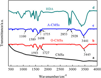
The functional groups of all samples were characterized by FTIR, as shown in Fig. 2. The as-synthesized CMSs [Fig. 2(a)] had hardly any absorption peaks. For O-CMSs [Fig. 2(b)], a broad band of –OH stretching vibration presented at around 3445 cm−1, and the bands at 1593, 1727 cm−1 were assigned to the –C–C and –C=O, respectively. It is indicated that the oxygen-containing functional groups were introduced onto the surface of CMSs. As shown in Fig. 2(c), after the amination reaction, A-CMSs presented the characteristic absorption bands of HDA [Fig. 2(d)]. The –C=O band at 1727 cm−1 was clearly weakened, because the amidation reaction of –COOH from O-CMSs and –NH2 from HDA occurred to form –HNCO– at 1698 cm−1. The –C=O at 1727 cm−1 shifted to 1735 cm−1 and the –C–C absorption at 1593 cm−1 shifted to 1589 cm−1. In addition, the –CN absorption appeared at 1100 cm−1 and –CH stretching vibration absorption appeared at 2853 and 2928 cm−1, respectively. Moreover, the absorption bands of A-CMSs had a small shift with respect to HDA. The above explanation suggests that A-CMSs were obtained through the reaction between the amino of HDA and carboxyl of O-CMSs.
FTIR spectra of (a) as-synthesized CMSs, (b) O-CMSs, (c) A-CMSs, and (d) HDA.

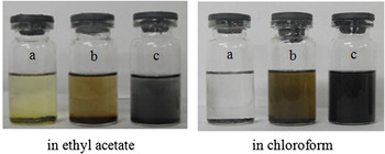
To investigate the dispersion of CMSs in organic solvents, ethyl acetate and chloroform were chosen. Figure 3 shows the dispersion of as-synthesized CMSs (a), O-CMSs (b), and A-CMSs (c) in ethyl acetate and chloroform for 10 min. It can be clearly seen that the as-synthesized CMSs were completely insoluble in ethyl acetate and chloroform and floated on the solvent and deposited at the bottom, suggesting that they had a poor dispersion. After oxidation modification of CMSs, the dispersion of O-CMSs had a slight improvement in ethyl acetate and chloroform owing to the introduction of polar groups. The amino functional groups on the surface of CMSs after modification with HDA made the surface polarity of CMSs weak, resulting in enhancement of dispersion in chloroform and ethyl acetate, especially in chloroform. Therefore, chloroform was chosen as a solvent for preparing polymer composite as solar PV materials.
The dispersion of (a) as-synthesized CMSs, (b) O-CMSs, and (c) A-CMSs in ethyl acetate and chloroform after holding for 10 min.

The electrochemical properties are important for deciding the highest occupied molecular orbital (HOMO) and lowest unoccupied molecular orbital (LUMO) energy levels (E
HOMO and E
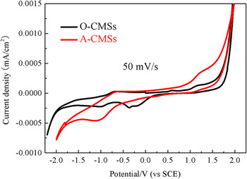
LUMO) of CMSs. Figure 4 shows the CV curves of O-CMSs and A-CMSs. Their electrochemical potentials and energy levels are listed in Table I. Figure 4 suggests that O-CMSs and A-CMSs displayed defined quasi-reversible oxidation and reduction peaks in the potential area. The E
HOMO and E
LUMO of O-CMSs and A-CMSs were calculated from their onset oxidation potential (
 $E_{\rm{0}}^{{\rm{ox}}}$
) and onset reduction potential (
 $E_{\rm{0}}^{{\rm{red}}}$
) observed in CV.
Reference Wang, Chesnut, Sun, Tong, Guide, Zhang, Treat, Varotto, Mayer, Chabinyc, Nguyen and Wudl12,Reference Lenes, Wetzelaer, Kooistra, Veenstra, Hummelen and Blom13
The
 $E_{\rm{0}}^{{\rm{ox}}}$
(
 $E_{\rm{0}}^{{\rm{red}}}$
) of O-CMSs and A-CMSs was observed at 1.18 (−0.98) and 1.23 (−1.09) V, respectively. Therefore, the E
HOMO (E
LUMO) of O-CMSs and A-CMSs was −5.92 (−3.76) and −5.97 (−3.65) eV, respectively, below the vacuum energy level, as can be calculated from Eqs. (1) and (2).
Reference Yang, Song, Han, Guo, Liu and Xu6
 $${E_{{\rm{HOMO}}}} = - {\rm{(}}E_{\rm{0}}^{{\rm{ox}}} + {\rm{4}}{\rm{.74)eV}}\quad {\rm{,}}$$
 $${E_{{\rm{LUMO}}}} = - {\rm{(}}E_{\rm{0}}^{{\rm{red}}} + {\rm{4}}{\rm{.74)eV}}\quad {\rm{.}}$$
CV curves of O-CMSs and A-CMSs.

Electrochemical properties of O-CMSs and A-CMSs.

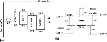
To guarantee efficient charge separation and high open circuit voltage, the matching of the LUMO and HOMO energy levels of the P3HT and CMSs is very important. The energy diagrams of the devices and the composite films are shown in Fig. 5. The difference between the energy levels of P3HT and CMSs, defined as ΔE 1 [E LUMO (D − A)] and ΔE 3 [E HOMO (D − A)], can be correlated with exciton dissociation. As excitons diffuse to the P3HT-CMS interface, the exciton binding energy (ΔE) must be overcome to dissociate excitons into free electrons and holes. For overcoming the ΔE, in general, the ΔE 1 and ΔE 3 should be larger than 0.4 eV. Reference Frechet and Thompson14 For O-CMSs and A-CMSs, ΔE 1 was 0.56 and 0.45 eV and ΔE 3 was 0.72 and 0.77 eV, respectively. Therefore, it might be feasible that CMSs act as the acceptor.
The energy diagrams of (a) the devices and (b) composite films.

The A-CMSs had higher E LUMO of −3.65 eV, 0.11 eV higher than that of O-CMSs. Because the –NH2, –CONH–, –C4H8– alkyl chains and other electron-donating groups were introduced by amination reaction, the reduction potential was reduced, resulting in an increase of E LUMO. Because the energy difference (ΔE 2) of E HOMO of donor material and E LUMO of acceptor material is proportional to the open circuit voltage (V oc) of the cells and can be increased by increasing E LUMO of acceptor material, the aminated CMSs with higher E LUMO raised V oc, thus the PCE of PSCs would be improved.
In our previous study, Reference Yang, Song, Li, Liu and Xu15 the influence of N,N′-DCC dosage (as condensing agent), reaction time, and reaction temperature on the aminated CMSs had been investigated. And the revolving speed and suspension concentration during spin coating had the same parameters as for the synthesis of P3HT:O-CMS composite films because of the similar particle size of A-CMSs and O-CMSs. In addition, the P3HT:O-CMS volume ratio was found to have tremendous influence on the morphology and optical properties of the composite films in our previous work. Reference Yang, Song, Li, Liu and Xu8 So, here we discuss the influence of the ratio of P3HT to A-CMSs on the composite films to choose the appropriate proportion for preparing PV devices.
The morphology of the composite film is very important in PSC devices. Reference Oosterhout, Wienk, Bavel, Thiedmann, Koster, Gilot, Loos, Schmidt and Janssen16 The morphologies of the P3HT:A-CMS composite films were investigated by AFM. Figure 6 shows the AFM images of the surface of the composite films (P3HT:A-CMSs of 1:2, 1:1, 2:1, w/w) prepared from chloroform solvents (30 mg/mL). When A-CMS:P3HT proportion was 1:2 [Fig. 6(a)], the film consisted of a large area of P3HT because of the small quantity of A-CMSs, which was not favorable for the interface charge delivery between the donor and acceptor. As A-CMS amount increased, the density of films improved. When the proportion was 1:1 [Fig. 6(b)], A-CMSs had a good dispersion in P3HT, thus an interpenetrating network structure in the composite film was formed. However, A-CMSs appeared a large area of aggregation when the ratio increased to 2:1 [Fig. 6(c)], resulting in the reduction of contact area of the donor–acceptor, which was not favorable for the enhancement of efficiency.
AFM images of P3HT:A-CMS composite films prepared under different ratios of A-CMSs to P3HT: (a) 1:2, (b) 1:1, and (c) 2:1.

The UV-Vis spectra of P3HT film and P3HT:A-CMS composite films prepared under suspension concentration of 30 mg/mL in chloroform solvents are shown in Fig. 7. The absorbance of films gradually decreased along with the increase of blending rate. It can be seen that three absorption peaks, corresponding to P3HT, appeared in a pure P3HT film [Fig. 7(a)]. The absorption strength of P3HT:A-CMS composite films was weakened, because the introduction of A-CMSs destroyed the molecular packing structure of P3HT. For P3HT:A-CMSs of 1:2 [Fig. 7(b)], the absorbance of composite films was strongest in the visible light region. With the increase of blending rate to the 1:1 [Fig. 7(c)], the absorbance of the film became weakened a little. Further increasing the rate to 1:2 [Fig. 7(d)], the absorbance was weakened obviously.
UV-Vis spectra of (a) P3HT film and P3HT:A-CMS composite films prepared under different ratios of A-CMSs to P3HT: (b) 1:2, (c) 1:1, and (d) 2:1.

To investigate the photoinduced charge transfer properties, PL spectra of P3HT film and P3HT:A-CMS composite films are shown in Fig. 8, which were obtained by exciting these films with ultraviolet at 450 nm. In Fig. 8, the excitons in the active layer were quenched by a photoinduced charge transfer process when introducing A-CMSs into composite films. When the blending rate was 2:1 and 1:1, the fluorescence quenching became more apparent. The lower intensity of PL spectra means the more effective separation of electron–hole pairs, leading to higher short-circuit currents (J sc) of the devices fabricated using P3HT:A-CMS composite films as the active layer. Reference Kim, Mi, Kim, Park, Yoon, Yoon and Kwang17 From AFM and UV-Vis analysis, the optimal blending rate of P3HT and A-CMSs was 1:1.
PL spectra of (a) P3HT film and P3HT:A-CMS composite films prepared under different ratios of A-CMSs to P3HT: (b) 1:2, (c) 1:1, and (d) 2:1.

Structural analysis of A-CMS film and P3HT:A-CMS composite films under the optimal blending rate of 1:1 is shown in Fig. 9. Compared with A-CMSs, P3HT:A-CMSs gave a similar adsorption band. The bands at 1619, 1697, 1736, and 3438 cm−1 were attributed to –C=O, –CONH–, –COOH, and –OH stretching vibrations, respectively, indicating that the structure of A-CMSs in the composite films was complete. Besides, the band of thiophene ring emerged at 719 cm−1, suggesting that the mixture of P3HT and A-CMSs had no effect on the characteristic bands of P3HT.
FTIR spectra of (a) A-CMSs and (b) P3HT:A-CMS composite films under the optimal blending rate of 1:1.

The structure of composite films was further characterized by XRD. Figure 10 illustrates the effect of annealing treatment on the structure of the P3HT:A-CMS composite films. The intense broad peak at 23.6° was associated with the (002) reflection of amorphous carbon layer in A-CMSs, and the unclear peak and rough line were due to the uneven film prepared by spin coating process. Reference Zheng, Wu, Shi, Guan and Yu18 More importantly, XRD pattern shows a peak at 5.2° assigned to the (100) reflection of the P3HT, Reference Xu, Zhang, Zhang, Wang, Zhuo, Liu, Wang and Xu19 which corresponded to the α-axis orientation of the P3HT crystallite, with the main polymer chains parallel and the side chains perpendicular to the substrate. Reference Karagiannidis, Kassavetis, Pitsalidis and Logothetidis20 Annealing could enhance the PCE of PSCs by the formation of an ordered structure of films.
XRD patterns of the P3HT:A-CMS thin films before and after annealing at 120 °C for 10 min (a) unannealed and (b) annealed.

To further confirm the effect of annealing on the order degree and exciton separation of the composite films, UV-Vis absorption spectra and PL spectra of P3HT:A-CMS thin films before and after annealing were measured, as shown in Figs. 11 and 12. Obviously, the intensity of the UV-Vis absorption peaks increased after the annealing treatment because of the improvement of the degree of ordering of P3HT, which helped the absorption of sunlight. However, the intensity of fluorescent peaks also increased, because the annealing treatment made the molecular chains of P3HT more ordered and its conjugation length increased, resulting in luminescence from exciton recombination of blended system.
UV-Vis spectra of the P3HT:A-CMS thin films before and after annealing at 120 °C for 10 min (a) unannealed and (b) annealed. Inset: the difference between the absorption intensities before and after annealing.

PL spectra of the P3HT:A-CMS thin films before and after annealing at 120 °C for 10 min (a) unannealed and (b) annealed.

The results indicate that increased crystallization of the P3HT in the composite film during annealing improved light-harvesting and charge carrier transport, although it presented higher charge carrier recombination after annealing treatment. Thus, the performance of PSCs was affected and improved overall in this study.
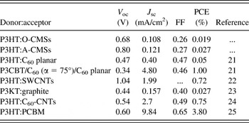
To evaluate the PV property of the P3HT:O-CMS and P3HT:A-CMS films, PSC devices with a typical sandwich structure of ITO/PEDOT:PSS/P3HT:(O-CMSs or A-CMSs)/Al were fabricated. Figure 13 shows the J–V curves of PSCs in the dark and under illumination (AM 1.5G illumination of 100 mW/cm2), and the corresponding PV data are summarized in Table II. From Fig. 13(a), it can be seen that dark current for the devices is almost nil at no bias condition. As shown in Fig. 13(b), PSCs fabricated using P3HT:O-CMS composite film showed V oc of 0.68 V, J sc of 0.108 mA/cm2, and PCE of 0.019%; PSCs fabricated using P3HT:A-CMS composite film showed V oc of 0.80 V, J sc of 0.121 mA/cm2, and PCE of 0.027%. The optimized film (P3HT:A-CMS composite film) utilized in PSC devices exhibited an approximately 40% enhancement in PCE with respect to P3HT:O-CMS composite film.
J–V curves of the PSCs fabricated using P3HT:O-CMS and P3HT:A-CMS films as the active layer (a) in the dark and (b) under illumination (AM 1.5 G illumination of 100 mW/cm2).

Summary of device performance of P3HT:O-CMSs, P3HT:A-CMSs, and other heterojunction composite films under 100 mW/cm2, AM1.5.

The V oc values of the P3HT:A-CMS-based PSCs was 0.80 V, 0.12 V higher than that of P3HT:O-CMS-based PSCs, as shown in Table II. Compared with other carbon material-based PSCs, Reference Thomas, Worfolk, Rider, Taschuk, Buriak and Brett21–Reference Subbiah, Amb, Irfan, Gao, Reynolds and So25 these CMSs show similar and even higher V oc. This is because the V oc values of PSCs were determined by the energy gap between the E LUMO of acceptor and the E HOMO of donor. Reference Scharber, Muhlbacjer, Koppe, Denk, Waldauf, Heeger and Brabec26 After amination modification, the increase in E LUMO of CMSs resulted in enhanced V oc. However, the remarkable difference between the CMSs and others was in J sc and PCE; the PCE values of CMS-based devices were still significantly lower than that of PCBM-based devices, that is, 3.80%. Reference Subbiah, Amb, Irfan, Gao, Reynolds and So25 These rather unsatisfactory PCE values in these bulk heterojunctions structures are attributed to the relatively low J sc. CMSs with a size of about 300 nm resulted in a large thickness of active layer, which did not match the exciton diffusion length to limit charge carrier transport and consequently gave low PCE. In contrast, the J sc for the fullerene-based devices was typically 0.3 mA/cm2. Reference Thomas, Worfolk, Rider, Taschuk, Buriak and Brett21,Reference Li and Mitraa24,Reference Subbiah, Amb, Irfan, Gao, Reynolds and So25 Therefore, further work is ongoing to increase device J sc, either by morphology control, such as manipulating CMS acceptor on the nanoscale or loading metal nanoparticles with the localized surface plasmon resonance effect, or by interface engineering to improve the performance of PSC devices.
IV. CONCLUSION
In summary, A-CMSs aminated by HDA, as electron-acceptor with the energy level matching with P3HT, had higher E LUMO than O-CMSs and as-synthesized CMSs, indicating that A-CMSs as an acceptor were feasible. The optimized blending ratio of P3HT:A-CMS composite films was 1:1 under 2500 rpm of spin-coating. After annealing treatment, the intensity of visible light absorption and the crystallization degree of the P3HT:A-CMS composite films were enhanced. The optimized films utilized in PSC devices exhibited an approximately 40% enhancement in PCE with a higher V oc of 0.80 V with respect to O-CMSs, suggesting that A-CMSs would be a promising acceptor for PSCs. This lay an experimental and theoretical foundation for the design of new acceptors for PV application. It is believed that the PV performance can be further enhanced by improving the CMS-based films and optimizing the PSC devices.
ACKNOWLEDGMENTS
This work was financially supported by the Program for Changjiang Scholar and Innovative Research Team in University (IRT0972), National Natural Science Foundation of China (21176169), International Science and Technology Cooperation Program of China (2012DFR50460), Ph.D. Programs Foundation of Ministry of Education of China (20101402110007), and Research Project Supported by Shanxi Provincial Key Innovative Research Team in Science and Technology (2012041011) and Shanxi Scholarship Council of China (2012-038).