1. Introduction
Panels of a satellite antenna are stowed to take the rocket to space and deployed to work in orbit. Generally, panels are extended and supported by deployable mechanisms for better accuracy and higher stiffness. Deployable mechanism is usually a linkage and its accuracy is affected by joint clearances and link length tolerances.Footnote 1
Clearances lead to uncertain behaviors to the end effector and the problem of error modeling concerning clearances is being studied persistently. Early in 2000, Ting et al. [Reference Ting, Zhu and Watkins1] studied the effects of multiple clearances in a closed loop on the final output using a virtual link model. Then, they further developed kinematic models for revolute and spherical joint clearances to estimate the angular error of a 3-RPR mechanism [Reference Ting, Hsu and Wang2] and spatial four, five-bar linkages [Reference Chan and Ting3], respectively. Tsai et al. [Reference Tsai and Lai4,Reference Tsai and Lai5] modeled the closed-loop constraint using screws and analyzed the positioning error of planar mechanisms concerning clearances. Huang et al. [Reference Liu, Huang and Chetwynd6] presented the error model for lower-mobility parallel mechanisms with screws and distinguished the compensable and uncompensable errors and applied this method to the accuracy analysis of a parallel machine tool [Reference Tian, Gao, Zhang and Huang7]. For closed-loop mechanisms, modeling with screws has the advantage of succinct expression over the other methods, and therefore screw-based methods are widely used in error modeling of mechanisms with clearances, such as those discussed by Frisoli [Reference Frisoli, Solazzi, Pellegrinetti and Bergamasco8], Cammarata [Reference Cammarata9], and Simas [Reference Simas and Gregorio10].
Apart from the well-appraised screw methods, many other methods were also developed. Li et al. [Reference Li, Ding and Chirikjian11] studied the angular output uncertainty of a planar linkage with multiple clearances via a Lie-group-based approach. Zhao [Reference Zhao, Guo and Hong12] also provided the error space analysis method with the help of Lie group. The above-mentioned methods conducted probability analysis with Lie group computations given proper distributions for clearances. Since clearances are bounded error sources, direct optimization methods [Reference Meng and Li13,Reference Meng, Zhang and Li14] and interval analysis methods [Reference Briot and Bonev15,Reference Yao, Zhu and Huang16] were also developed for maximum errors estimation. Though plenty of error modeling methods regarding clearances have been developed, they focused on limited information of the final output errors, such as probability and maximum, and they are not capable of or efficient in entire error space analysis. In view of this, geometric methods [Reference Chen, Wang and Lin17,Reference Ding, Lyu, Da, Wang and Chirikjian18] were proposed for entire error mobility analysis and illustrated with planar 3-RPR mechanisms.
Besides joint clearances, link length deviations are also inevitable and bring in output errors of end effector. Kumaraswamy et al. [Reference Kumaraswamy, Shunmugam and Sujatha19] applied the screws to model the clearances and tolerances and studied their effects on path generation. Huang et al. [Reference Huang, David and Derek20] improved the accuracy of lower-mobility parallel mechanisms considering tolerances by optimizing the assembly process. Most of the existing tolerance design methods aim to optimize tolerances to compromise accuracy and manufacturing cost [Reference Martin, Benjamin and Sandro21]. Coupled effects of clearances are not included. Therefore, in this paper, for a deployable mechanism used to unfold and support satellite antenna panels, a geometrical method is introduced to give the error space of the mechanism regarding both clearances and tolerances. Compared with the existing methods, the proposed geometrical method studies the positioning and orientating errors simultaneously, and it gives the expression of the entire error space. Effects of tolerance allocations on accuracy are studied aiming to improve the accuracy of the antenna mechanism by optimizing tolerance allocation without increasing the manufacturing cost.
The rest of the paper is organized as follows. In the next section, the deployable mechanism is introduced and its planar representation is given, following which the error space of the mechanism considering multiple clearances and tolerances is defined and deduced using a proposed geometrical method. Section 3 presents the study on the effects of various tolerance designs on the accuracy of the mechanism. Finally, we conclude our study in Section 4.
2. Error space modeling
2.1 Deployable mechanism modeling
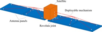
The deployable mechanism discussed here is used to deploy and support antenna panels of a Synthetic Aperture Radar (SAR) and its deployed structure is charactered in Fig.1.
Schematic Diagram of the deployed supporting mechanism in SAR.

As shown in Fig.1, the deployable mechanism is an articulated spatial linkage that is symmetric in the
 $O-xy$
plane. Moreover, its unfolding motion is also constrained in the same plane. We care about its angular accuracy about the
 $o-z$
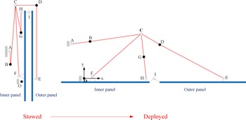
axis most. Therefore, it is convenient to study its kinematics performance in a plane and its planar representation is give in Fig. 2.
Planar representation of the deployable mechanism.

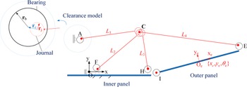
In Fig. 2, capital letters denote revolute joints. In order to have determined motion, the mechanism is actuated by a motor at O and three auxiliary torsional springs at B, D, and G, respectively, and they are locked after deployment to support the deployed panels. Two panels are designed to be coplanar when they are completely unfolded. However, in practice, the outer panel can still move freely in a small range after the mechanism is locked due to passive joint clearances and the gravity-free working condition in orbit. Error model of the deployable mechanism regarding revolute clearances in its deployed state is depicted in Fig. 3.
Error model of the deployable mechanism.

Clearances of the locked joints are not included in the error model. Therefore, we simplified links AB and BC into a single link AC with length
 $L_1$
, and analogously, we obtain the equivalently simplified links CH and CE. No penetration is considered and the clearance is modeled with the commonly used virtual link. Length of the virtual link is computed as:
 \begin{equation} r_c = x, \quad x\in[0,r_b-r_j],\end{equation}
where
 $r_b$
and
 $r_j$
are the radii of bearing and journal, respectively.
In the error model, the inner panel is error-free due to the locked O and the outer panel may locate randomly within a small range. The midpoint
 $O_e$
of IE and the body coordinate system
 $O_e-x_ey_e$
are used to indicate the pose of the outer panel. Given that the error-free pose and the real pose of the outer panel in global frame
 $O-xy$
are
 $\mathbf{g}_0$
and
 $\mathbf{g}_e$
, respectively, we have
 \begin{equation} \mathbf{g}_e = \mathbf{g}_0\circ\exp\left(\begin{array}{c@{\quad}c@{\quad}c} 0 & \!\!-\theta_e & x_e\\ \theta_e & 0 & y_e\\ 0 & 0 & 0 \end{array}\right),\end{equation}
where
 $\mathbf{g}_0$
and
 $\mathbf{g}_e$
are elements of Lie group SE(2), and
 $[x_e,y_e]^\top$
and
 $\theta_e$
are the positioning error and orientation error, respectively. And the error space of the deployable mechanism is defined as the set of all
 $[x_e,y_e,\theta_e]^\top$
.
2.2 Error space estimation
Apart from the revolute joint clearances, link length tolerances are also considered to estimate the error space. In practice, the inner panel and outer panel are fixed to metal frames and revolute joints I and E are also connected to the frames. Moreover, the connection positions of joints at the frames are adjustable; therefore, errors of the panels brought by tolerances and assembling process can be calibrated and greatly reduced. Then, tolerances of the panels are excluded in this paper. Only the clearances of rods are considered. A geometrical approach is discussed here for error propagation and accumulation analysis.
As discussed previously, the clearance can be represented by a virtual link with maximum length of
 $r = r_b-r_j$
. Therefore, geometrically, the journal can move freely inside a disk region. Then, it is convenient to use the disk of radius r to represent the error space of a revolute joint. In this way, taking joint F and link FC as an example, the error propagation and accumulation are modeled, as shown in Fig. 4.
Error propagation and accumulation in an open loop.

In Fig. 4, the error space of joint F due to clearance is represented by a disk with radius
 $r_1$
, the length of link FC regarding tolerance is in the interval
 $[L_2-t_{d2},L_2+t_{u2}]$
. The error space at C can be obtained by translating disk from F to C and Mincowski adding with vector
 $t_d$
and
 $t_u$
. In a plane, the translation of a region
 $\mathcal{M}$
with a vector
 $\mathbf{t}$
is defined as:
 \begin{equation} \mathcal{M}+ \mathbf{t} \doteq \left( \begin{array}{c}x_m\\y_m\end{array}\right) +\mathbf{t},\end{equation}
where
 $(x_m,y_m)^\top$
is any point in
 $\mathcal{M}$
.
Since the mobility of revolute joint F is not constrained in an open loop, the final error space of C is obtained by rotating the error region generated previously, and finally a ring region is got, suggesting that point C can locate at any position in that ring region. The quadric expression of a planar circle is used to define
 $\mathcal{C}_{\mathbf{x}_0,R} $
, as:
 \begin{equation} \mathcal{C}_{\mathbf{x}_0,R} \doteq (\mathbf{x}-\mathbf{x}_0)^\top\mathbf{Q}(\mathbf{x}-\mathbf{x}_0) - 1\end{equation}
where
 $\mathbf{x}$
is any point in a plane,
 $\mathbf{x}_0$
is the center of a circle, R is the radius of a circle, and
 $\mathbf{Q}$
is a
 $2\times2$
diagonal matrix, as:
 \begin{equation} \mathbf{Q} = \left(\begin{array}{c@{\quad}c} \dfrac{1}{R^2} & 0\\[5pt] 0 & \dfrac{1}{R^2} \end{array}\right).\end{equation}
Then the error space of C considering clearance at F and tolerance can be expressed as:
 \begin{equation} \mathcal{M}_C =\{\mathcal{C}_{\mathbf{x}_C,L_2-r_1-t_{d2}}\geq 0\} \cap \{\mathcal{C}_{\mathbf{x}_C,L_2+r_1+t_{u2}}\leq 0\} \end{equation}
where
 $\mathbf{x}_c$
denotes the error-free coordinates of C.
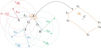
Now that the geometric expression of clearance and tolerance propagating and accumulating in the open loop is obtained, and the error space in the closed loop is to be derived next. As shown in Fig. 3, the deployable mechanism owns a multi-closed-loop structure, and the error propagation path should be studied before estimating the final error space of panel IE. Obviously, for the deployable mechanism, error spaces at joints A, F, H, and I are only decided by their own clearances, the error space of C is decided in multiple loops ACF and FCH, and the error space of E is decided by joint C, link CE and its own clearance. Then, the error space of C is geometrically modeled, as shown in Fig. 5.
Error space of joint C.

In Fig. 5,
 $\{r_{A1},r_{A2}\},\{r_{F1},r_{F2}\}$
, and
 $\{r_{H1},r_{H2}\}$
are radii of rings representing the error spaces of A, F, and H, respectively. As discussed previously, error spaces at C in open loops AC, FC, and HC can be represented by rings denoted as
 $^A\mathcal{M}_C$
,
 $^F\mathcal{M}_C$
, and
 $^H\mathcal{M}_C$
, respectively, as shown in Fig. 5. Given that all joints are of the same size
 $r_1$
and complex revolute joints at C share the common journal that is fixed with link CE, referring to Eq. (6), the propagated error spaces are expressed as:
 \begin{equation} \begin{array}{l} ^A\mathcal{M}_C =\{\mathcal{C}_{\mathbf{x}_A,r_{A1}}\geq 0\} \cap \{\mathcal{C}_{\mathbf{x}_A,r_{A2}}\leq 0\}\\[5pt] ^F\mathcal{M}_C =\{\mathcal{C}_{\mathbf{x}_F,r_{F1}}\geq 0\} \cap \{\mathcal{C}_{\mathbf{x}_F,r_{F2}}\leq 0\}\\[5pt] ^H\mathcal{M}_C =\{\mathcal{C}_{\mathbf{x}_H,r_{H1}}\geq 0\} \cap \{\mathcal{C}_{\mathbf{x}_H,r_{H2}}\leq 0\} \end{array}, \end{equation}
where
 \begin{equation} \begin{array}{l} r_{A1} = L_1-2r_1-t_{d1}\\[5pt] r_{A2} = L_1+2r_1+t_{u1}\\[5pt] r_{F1} = L_2-2r_1-t_{d2}\\[5pt] r_{F2} = L_2+2r_1+t_{u2}\\[5pt] r_{H1} = L_3-2r_1-t_{d3}\\[5pt] r_{H2} = L_3+2r_1+t_{u3} \end{array}\end{equation}
where
 $L_1$
,
 $L_2$
, and
 $L_3$
are lengths of links AC, FC, and HC, respectively, and their tolerances are
 $[\!-\!t_{d1},t_{u1}]$
,
 $[\!-\!t_{d2},t_{u2}]$
, and
 $[\!-\!t_{d3},t_{u3}]$
, respectively.
Therefore, when considering closed-loop constraints, the error space indicating all the positions journal C can locate is expressed as:
 \begin{equation} \mathcal{M}_C = ^A\mathcal{M}_C \cap ^F\mathcal{M}_C \cap ^H\mathcal{M}_C ,\end{equation}
suggesting the intersection region of three rings. Generally, three rings can intersect at up to 24 individual points, and the shape of the error space depends on the intersection situation. Intersection points used for error space computation must satisfy the Eq. (7). As shown in Fig. 5, the error region of C has six intersection points.
As discussed previously, error space of E is computed in the open loop CE, and it consists of the error space propagated from C, error space arisen from length tolerance of
 $L_4$
and its sole clearance. The propagated part is modeled first, as shown in Fig. 6.
Error space of joint E.

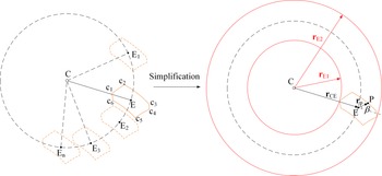
Despite of closed-loop constraint, the trajectory of E is a circle with radius
 $L_3$
and center
 $\mathbf{C}$
. When the error space of C is considered, the error space of E arisen from C can be obtained by translating (without rotation)
 $\mathcal{M}_C$
to every position on the trajectory of E. The region enclosing all translated
 $\mathcal{M}_C$
is the error space of E propagated from C, denoted as
 $^C\mathcal{M}_E$
. However, the contour of
 $^C\mathcal{M}_E$
is difficult to express with equations. Then, a simplified ring is used to substitute the
 $^C\mathcal{M}_E$
. Using the
 $\mathcal{M}_C$
translated to the error-free position of E, the radii of the substituting ring are computed. Given that P is an arbitrary point on
 $\mathcal{M}_C$
at E,
 $\mathbf{r}_P$
is a vector from E to P and
 $\mathbf{r}_{CE}$
is a vector from C to E, then the projection of
 $\mathbf{r}_P$
on CE is computed as:
 \begin{equation} \mathbf{r}_{P1} = \frac{(\mathbf{r}_{P}\cdot\mathbf{r}_{CE})\mathbf{r}_{CE}}{|\mathbf{r}_{CE}|}\end{equation}
Then, the radii of the ring are computed as:
 \begin{equation} \begin{array}{l} {r}_{E1} = L_3 + \min({\mathbf{r}_{P1}})\\ {r}_{E2} = L_3 + \max({\mathbf{r}_{P1}}) \end{array} \end{equation}
When the length tolerance
 $[\!-\!t_{d4}, t_{u4}]$
and clearance of E are included, the finale error space of E is expressed as:
 \begin{equation} \mathcal{M}_E = \{\mathcal{C}_{\mathbf{x}_C,{r}_{E1}-r_1-t_{d4}}\geq 0\} \cap \{\mathcal{C}_{\mathbf{x}_C,{r}_{E1}+r_1+t_{u4}}\leq 0\} \end{equation}
Since joint I is fixed to the error-free inner panel, the error space of I is a disk with radius
 $r_1$
, denoted as
 $\mathcal{M}_I$
. Then, error space estimation of the outer panel is to find all the possible mobilities of
 $O_e-x_ey_e$
when two ends of segment IE are strictly restrained in
 $\mathcal{M}_I$
and
 $\mathcal{M}_E$
, respectively, as shown in Fig. 7.
Positioning error space of the outer panel given
 $\theta = 0$
.

In Fig. 7,
 $\theta$
is the orientating error. The positioning error space of the outer panel is obtained by translating
 $\mathcal{M}_I$
and
 $\mathcal{M}_E$
to the common point
 $O_e$
and computing the intersected region. A planar disk translated by a vector is expressed as:
 \begin{equation} \mathcal{C}_{\mathbf{x}_0,R} + \mathbf{t} \doteq \mathcal{C}_{\mathbf{x}_0+\mathbf{t},R}\end{equation}
Then, the position error space of the outer panel is expressed as:
 \begin{equation} \mathcal{M}_P = \{\mathcal{C}_{\mathbf{x}_C+\mathbf{r}_{EO} ,{r}_{d}}\geq 0\} \cap \{\mathcal{C}_{\mathbf{x}_C+\mathbf{r}_{EO},r_u}\leq 0\} \cap \{\mathcal{C}_{\mathbf{x}_I + \mathbf{r}_{IO},r_1} \leq 0\}\end{equation}
Referring to Eq. (12),
 $r_d = {r}_{E1}-r_1-t_{d4}$
and
 $r_u = {r}_{E1}+r_1+t_{u4}$
. When angular error is considered, the positioning error space of the outer panel is computed, as shown in Fig. 8.
Positioning error space of the outer panel given
 $\theta_e$
.

The positioning error space with angular error
 $\theta_e$
can be obtained by first rotating vectors
 $\mathbf{r}_{IO_e}$
and
 $\mathbf{r}_{EO_e}$
by
 $\theta_e$
, then translating
 $\mathcal{M}_I$
and
 $\mathcal{M}_E$
by rotated vectors
 $\mathbf{r}_{IO2}$
and
 $\mathbf{r}_{EO2}$
, respectively, and computing the intersection region. The complete error space of the outer panel is the unite of all the positioning error spaces, modeled as planar regions, of all possible angular errors. It is expressed as:
 \begin{equation} \mathcal{M} = \bigcup_{\mathbf{R}_{\theta} \in SO(2)} \{\mathcal{C}_{\mathbf{x}_C+\mathbf{R}_{\theta}\mathbf{r}_{EO} ,{r}_{d}}\geq 0\} \cap \{\mathcal{C}_{\mathbf{x}_C+\mathbf{R}_{\theta}\mathbf{r}_{EO},r_u}\leq 0\} \cap \{\mathcal{C}_{\mathbf{x}_I + \mathbf{R}_{\theta}\mathbf{r}_{IO},r_1} \leq 0\}, \end{equation}
where
 $\mathbf{R}_{\theta}$
denotes the planar rotation and is expressed as:
 \begin{equation} \mathbf{R}_{\theta} = \left(\begin{array}{c@{\quad}c} \cos\theta & -\!\sin\theta\\[5pt] \sin\theta & \cos\theta \end{array}\right).\end{equation}
It is noteworthy that the angular error
 $\theta$
is usually rather small. When
 $|\theta|$
is large, we have
 $\mathcal{M} = \emptyset$
. It is difficult to evaluate Eq. (15) and it can be approximated numerically as:
 \begin{equation} \left\{\begin{array}{l} \mathcal{M} = \sum\limits_{i = 1 }^N [ \{\mathcal{C}_{\mathbf{x}_C+\mathbf{R}_{\theta_i}\mathbf{r}_{EO} ,{r}_{d}}\geq 0\} \cap\{\mathcal{C}_{\mathbf{x}_C+\mathbf{R}_{\theta_i}\mathbf{r}_{EO},r_u}\leq 0\} \cap\{\mathcal{C}_{\mathbf{x}_I + \mathbf{R}_{\theta_i}\mathbf{r}_{IO},r_1} \leq 0\} ] \\[5pt] \theta_i = -\pi + \frac{2\pi i}{N} \end{array}\right.,\end{equation}
where N is the number of slices that represent positioning errors under certain orientations.
Given that tolerances are
 $1/1000$
of link lengths. Parameters used for error space estimation of the deployable mechanism are presented in Table I.
Parameter settings.

Visualization of the final error space.

We sample on x with increment of
 $0.02$
mm, y with increment of
 $0.2$
mm, and
 $\theta$
with increment of
 $0.02^\circ$
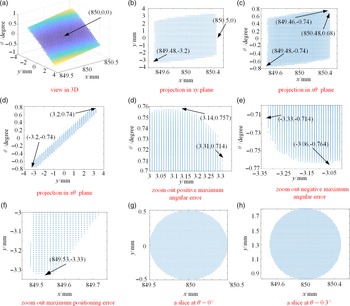
, and the error space of the outer panel is visualized in the three-dimensional Cartesian frame
 $\{x,y,\theta\}$
, as shown in Fig. 9(a). It is noteworthy that the x-axis, y-axis, and
 $\theta$
-axis are not in the same scale, so the shape displayed in Fig. 9(a) is deformed.
The error-free pose of the outer panel is given as (850,0,0). It can be observed in Fig. 9 that the positioning error in the x-direction is restrained in [
 $-0.52$
mm,
 $0.5$
mm], the positioning error projected in the x-direction is restrained in [
 $-3.33$
mm,
 $3.31$
mm], and angular error is restrained in
 $[\!-\!0.764^\circ,0.757^\circ]$
. Moreover, the maximum positioning error is
 $3.36$
mm at
 $(849.53,-3.33,-0.714)$
. Since the error space of I (represented by a disk with radius
 $0.5$
mm) is much smaller than that of E (represented by a ring with width
 $4.94$
mm), the positioning error is coupled with the angular error, and the translational mobility is mainly determined by
 $\mathcal{M}_I$
when angular error is fixed, as shown in Fig. 9(g) and (h). The error space of the outer panel is like a cylinder subjected to shear deformation in shape, two ends of which converge to two individual points. In Fig. 9, the translational mobility at any given rotation can be obtained, which gives a deep insight of the accuracy performance of the outer panel.
3. Accuracy analysis with various tolerance design
This section aims to study the effects of tolerances on the final accuracy. Here, tolerances are restrained
 $1/1000$
of link lengths. Three limited cases for each link tolerance allocation are considered, as shown in Table II.
There are 81 combinations in total and the maximum
 $\theta_e$
is computed because it have great influence on the collinearity of the two panels. The results are presented in the Appendix A.
It can be observed from Tables A.1 and A.2 in the appendix that tolerance design (
 $[\!-\!t_{d2},t_{u2}]$
) of link FC (
 $L_2$
) makes no difference on the maximum positioning error
 $y_e$
and angular error
 $\theta_e$
, suggesting that the tolerance of link FC has no contribution to the radii of
 $^C\mathcal{M}_E$
. The optimal situation occurs at
 $[\!-\!0.25,0.25]$
for
 $L_1$
,
 $[\!-\!0.15,0.15]$
for
 $L_3$
, and
 $[\!-\!0.34,0.34]$
for
 $L_4$
, and the maximum angular error is
 $0.764^\circ$
, see cases 32, 41 in Table A.1 and case 50 in Table A.2. In this situation, tolerances of
 $L_1$
,
 $L_3$
, and
 $L_4$
are centrosymmetric. Conversely, when the tolerances of
 $L_1$
and
 $L_4$
take the upper bounds and the tolerance of
 $L_3$
takes the lower bound as
 $[500_{0}^{+0.5}]$
,
 $[670.82_{0}^{+0.68}]$
, and
 $[300_{-0.3}^{0}]$
, respectively, it gives the worst situation with maximum angular error
 $\theta_e = 0.926^\circ$
, see cases 57, 66, and 75 in Table A.2.
Moreover, the accuracy without tolerances is computed for comparison. The maximum angular error only considering clearances is
 $\theta_e =0.764^\circ $
, which is the same as that computed with the optimal tolerance design, suggesting that the errors brought by tolerances can be eliminated by proper tolerance design for this specific deployable mechanism.
Tolerance allocation.

4. Conclusion
The error space of the deployable mechanism concerning revolute joint clearances and link tolerances is derived using a geometric approach and estimated numerically with discrete sampling points. The maximum positioning error and angular error are therefore obtained. In this numerical way, the precision of the result depends on the distances between sample points. It is noteworthy that points on the boundaries of the error space can also be obtained directly by solving equations. For the deployable mechanism discussed in this paper, the positioning error of the outer panel in the x-direction is mainly determined by the clearance of joint I. The error in y-direction and the angular error are coupled. When the angular error is fixed, the translational mobility of the outer panel is determined by the clearance of joint I.
Effects of tolerances on the accuracy are studied. It can be concluded from the results that the tolerance of link FC makes no difference to the final error when tolerance range is restrained to be 1/1000 the link length. The reason is that the position of C is redundantly determined by three links, among which AC and HC contribute most in propagation. Through the comparison with the clearances-only result, it reveals that the effects of tolerances on final error can be eliminated by proper tolerance design.
It is noteworthy that only the planar accuracy of the outer panel is investigated in this paper and geometrical errors, such as assembly errors, are ignored. However, in practice, as a spatial mechanism, revolute joint clearances can result in errors outside the O-xy plane. Then, in future studies, the proposed geometrical method will be extended and applied to error modeling of spatial mechanisms.
Acknowledgment
The authors would like to thank the support by State Key Laboratory of Robotics and Systems (HIT) (Grant No. SKLRS-2021-KF-01).
Author Contributions
J. Ding proposed the idea and wrote this paper, Y. Dong and X. Liu gave useful suggestions. This paper is finished under the instruction of C. Wang.
Conflicts of Interest
The authors declare that they have no known competing financial interests or personal relationships that could have appeared to influence the work reported in this paper.
Ethical Considerations
None.
A. Results of the Tolerance Design
Tolerance analysis results-1.

Tolerance analysis results-2.