I. INTRODUCTION
Bulk metallic glasses (BMGs), during the past few decades have emerged with eye catching properties. BMG has no long-range atomic order. Reference Johnson1,Reference Trexler and Thadhani2 Lacking in long-range atomic arrangement, they are free from defects present in the crystalline structure. They possess high strength and high elastic strain, but their structural applications are limited because of their low plasticity. Reference Yavari, Lewandowski and Eckert3 In comparison to other crystalline alloys of identical composition, these materials excel in mechanical, magnetic, and corrosion properties. Reference Suryanarayana and Anantharaman4–Reference Eckert, Das, Pauly and Duhamel6 Machining is one of the important manufacturing techniques used to generate parts with complicated shapes and high dimensional accuracy. To enhance the applications of BMGs, establishment of suitable machining techniques with effectiveness and precision is imperative. Since BMG is a relatively new class of materials, most of the research was dedicated to the investigation of its structural and thermal characteristics. So, the deformation behavior and the mechanism of chip formation in BMG cutting processes are poorly understood, to date. So far, limited work has been carried out on the machining (cutting, drilling, grinding, etc.) of BMGs. Reference Fujita, Morishita, Nishiyama, Kimura and Inoue7–Reference Bakkal, Shih, McSpadden and Scattergood10
Among various machining techniques, drilling is an important process for hole making. Drilling is relatively more complicated than the turning process in reference to tool geometry and work piece deformation. Deformation characteristics of the drilling process for BMG are not well understood yet. To our knowledge, very limited literature is available on the drilling behavior of BMGs. Reference Bakkal, Shih, McSpadden, Liu and Scattergood9,Reference Bakkal, Shih, McSpadden and Scattergood10 In this study, an attempt has been made to understand the drilling behavior of a Zr-based BMG for its use in industry in near future. In the present work, chip morphology, light emission, and burr formation during drilling of BMG were studied using drill bits of two different materials [high-speed steel (HSS) and carbide] at various operating conditions. A feasible operating range was investigated to generate multiple parts without light emission. It is envisaged that the finding of this work would be very useful for future industrial applications of BMGs.
II. EXPERIMENTAL
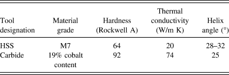
A Zr-based BMG plate of nominal composition Zr57.5Cu11.2Ni13.8Al17.5 with dimensions 50 × 8 × 3 mm was synthesized by arc melting a mixture of high-purity Zr, Cu, Ni, and Al metals. The details of the synthesis can be found elsewhere. Reference Tariq, Hassan, Akhter and Ali11 To confirm the amorphous nature of the as-cast and drilled BMG alloy, x-ray diffraction (XRD) was conducted using Cu Kα1 radiation (λ = 1.54060 Å). Differential scanning calorimetry (DSC) was carried out to evaluate thermal parameters for the alloy at a heating rate of 20 K/min. Drilling experiments were conducted on a numerically controlled drilling machine. The polished specimen was held in machine vice during experimentation. Drilling was performed using two different drill bits, i.e., HSS and carbide. The physical properties of both drill bits are shown in Table I. All drill bits were used in the uncoated condition with a point angle of 118° and two-flute drill geometry. The chips generated during various drilling experiments were collected and analyzed under a scanning electron microscope.
Properties of tool materials used for drilling operation.

III. EXPERIMENT DESIGN
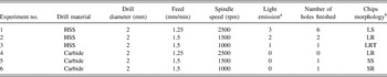
Six experiments were designed to achieve a feasible operating range for flawless drilling of Zr-based BMG. The details of experiments are given in Table II and summarized as follows:
-
(i) Experiment 1. Drill size effect: 1.25-mm/min feed rate of a 2-mm-diameter HSS drill bit at 2500-rpm spindle speed.
-
(ii) Experiment 2. Spindle speed effect: 1.5-mm/min feed rate using a HSS drill bit of 2-mm diameter operating at 1500-rpm spindle speed.
-
(iii) Experiment 3. Spindle speed effect: 1.5-mm/min feed rate using a HSS drill bit of 2-mm diameter operating at 1000-rpm spindle speed. Results compared to experiment 2.
-
(iv) Experiment 4. Tool material effect: 1.25-mm/min feed rate of a 2-mm-diameter carbide drill bit operating at 2500 rpm. Results compared with experiment 1.
-
(v) Experiment 5. Spindle speed and tool material effect: 1.5-mm/min feed rate using a carbide bit of 2-mm diameter at 1500-rpm spindle speed.
-
(vi) Experiment 6. Spindle speed and tool material effect: 1.5-mm/min feed rate using a carbide drill bit of diameter 2 mm operating at 1000-rpm spindle speed (compared to experiments 3 and 5).
Summary of various operating parameters used for drilling and corresponding observations.

a Light emission level: 0, no sparking; 1, sparsely sparking; 2, periodically continuous sparking; 3, extensive sparking.
b Chips morphology: SR, short ribbon; LRT, long ribbon tangled; SS, short spiral; LR, long ribbon; LS, long spiral.
IV. STRUCTURAL AND THERMAL INVESTIGATION
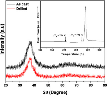
The XRD pattern of as-cast and drilled BMG samples is shown in Fig. 1. A typical broad band, indicative of the amorphous structure, was observed before and after drilling operation. The DSC curve of the as-cast BMG at a heating rate of 20 K/min is shown as an inset of Fig. 1. The DSC trace exhibited a single endothermic event, indicating the glass transition T g, and an exothermic event showing single stage crystallization reaction in the alloy. It also confirmed the amorphous nature of the alloy. The glass transition temperature, T g, the onset temperature of exothermic reaction, T x , and supercooled liquid region, ΔT x , were found to be 704, 775, and 71 K, respectively (Fig. 1).
XRD pattern of as-cast and drilled BMG samples; the inset shows the DSC curve of as-cast BMG at 20 K/min.

V. CHIP LIGHT EMISSION
Light emission phenomenon is considered the most unique feature in drilling of BMG. Light emission depends on the specimen properties, process parameters like feed rate and spindle speed, and also on the tool material properties. During machining, once the cutting speed exceeds the threshold value, phenomena of light emission is observed because of oxidation of the newly generated surface. Reference Bakkal, Liu, Watkins, Scattergood and Shih12–Reference Bakkal, Shih and Scattergood14 This phenomenon was observed in some of the drilling process of BMGs. Bakkal et al. Reference Bakkal, Shih and Scattergood14 identified cutting speed as a key process parameter to trigger light emission during turning operation of BMG. In the present work, experiments are designed in a manner to examine the conditions that cause light emission during drilling operation. Drill bits of different thermal conductivities were used for drilling operation. This property also affects the light emission during machining. Light emission level is subdivided into multiple states based upon their intensity and emission frequency as given in Table II.
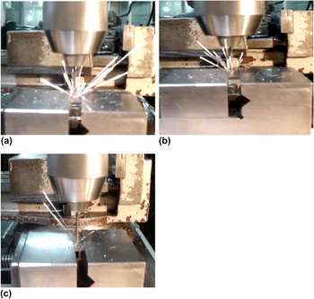
In Exp. 1 of this study, HSS drill bit was used at specified operating conditions. These operating conditions are same as were used by Bakkal et al. Reference Bakkal, Shih, McSpadden, Liu and Scattergood9 However, the only difference was the size of the drill bit used for drilling operation. In this case, extensive sparking was observed during drilling of hole in contrast to the Bakkal et al. Reference Bakkal, Shih, McSpadden, Liu and Scattergood9 observations, as shown in Fig. 2(a). This indicates the effect of drill diameter. The increase in the drill bit diameter results in large cutting forces which promote light emission. The drilling operation was carried out in dry conditions at a low feed rate. Lower feed rate allowed more time to keep tool and workpiece in contact. It also enhanced the effect of rubbing. As a result, more light emission took place.
Light emission observed using HSS drill bit: (a) extensive sparking in Exp. 1, (b) continuous periodic sparking in Exp. 2, and (c) sparsely sparking in Exp. 3.

In Exp. 2 and 3, the feed rate was kept constant to understand the effect of spindle speed on light emission. At high speed, the drill has high peripheral cutting speed, which initiates more oxidation in comparison to lower spindle speed. As a result, more light emission was observed in Exp. 2 as shown in Fig. 2(b). In comparison to periodic light emission in Exp. 2, sparsely sparking was observed in the case of Exp. 3 as shown in Fig. 2(c). Although, the level of light emission in Exp. 2 was not as vast as that in the case of Exp. 1. As discussed earlier, the lower feed rate and high spindle speed, both factors trigger the light emission. Exp. 1 reflects the effect of these two factors in comparison to Exp. 2 and 3.
To study the effect of a drill bit with high thermal conductivity in comparison to HSS drill bit, Exp. 1–3 were repeated using Carbide drill bit under the same machining environment and operating conditions. In this case, no light emission was observed in Exp 4. In this case, the major part of heat generated during drilling operation was transferred to the carbide bit instead of drilling chips which created hindrance to light emission.
In Exp. 5 and 6, although the increase in spindle speed resulted in more peripheral cutting speed, no light emission was observed. In this case, high thermal conductivity of the carbide drill bit (74 W/m K) in comparison to HSS drill bit (20 W/m K) overcomes this factor. Hence, no light emission was observed during machining under these conditions.
VI. CHIP MORPHOLOGY
In drilling, the material is removed in the form of chips. These chips can be of different sizes and shapes depending on the workpiece, tool materials, operating parameters, and drill bit geometry. Chip morphology observed in all six experiments was categorized into five types namely short ribbon, short spiral, long ribbon, long spiral, and long ribbon tangled as listed in Table II. These different morphologies will be discussed in detail as follows:
A. Long spiral
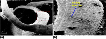
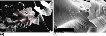
Long spiral chip morphology was observed in Exp. 1, as shown in Fig. 3(b). This profile has not been seen in any other experiment indicating that slower feed rates promote generation of long spiral chips. The chip was examined under a scanning electron microscope to reveal its morphology at higher magnification. Figure 3 shows micrographs at two different magnification levels. A close up view revealed saw-tooth-like edges and serrated chip morphology. Moreover, a regular lamellar structure with constant spacing and shear localization Reference Bakkal, Shih and Scattergood14 was observed in all chip morphologies perpendicular to the cutting direction. Interestingly, no typical BMG fractured morphologies, i.e., vein-like, river-like, or dimple-like, were observed. It is believed that this lamellar chip morphology might result from periodic shear bands formation originating at the tool–contact surface toward the opposite chip surface in the primary shear zone. Reference Jiang and Dai8 The deformation in BMGs normally takes place with the formation of shear bands resulting from the creation of free volume and localized thermal softening due to adiabatic heating. Reference Tariq, Hassan, Akhter and Ali11
Scanning electron microscope image of the long spiral BMG chip observed in Exp. 1: (a) at low magnification and (b) the magnified view of the rectangular area selected in Fig. 3(a).

B. Long ribbon
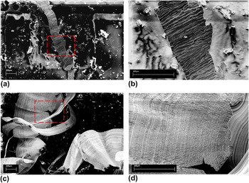
A long ribbon chip profile was generated in Exp. 2. This chip profile was thicker and did not break after hitting the flute. Feed rate in this experiment was higher than that in Exp. 1. Figure 4 shows micrographs at two magnification levels. A close up view of the generated chip revealed some built-up edges as well as an irregular lamellar structure with variable spacing perpendicular to the cutting direction [Fig. 4(b)]. This indicates nonuniform stress distribution between the tool and the contact surface, thus resulting in poor surface finish. A similar chip profile was also observed during the milling operation of aeronautical alloys. Reference Lopez de lacalle, Perez, Llorente and Sanchez15 Under different operating parameters, the same chip profile was observed in Exp. 4 using the carbide drill bit. However, in this case, the built-up edges became larger, and the chip becomes unstable and eventually broke apart. A close-up view of the rectangular box in Fig. 4(c) shows some crack propagation, which results in chip breakage [Fig. 4(d)].
Scanning electron microscope image revealing the long ribbon chip profile: (a) chip profile generated using HSS bit, (b) close up view of the rectangular box in Fig. 4(a) showing built-up edges, (c) chip profile in Exp. 4 using carbide bit, (d) close up view of the rectangular box in Fig. 4(c) showing breakage of chip at edges.

C. Long ribbon tangled
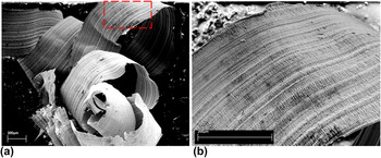
A long ribbon tangled chip profile was generated in Exp. 3. This unique profile was observed at 1000 rpm with sparse light emission. This light emission might have resulted in some level of chip oxidation. In this experiment, the chip leaves the tool in a continuous long ribbon form, which eventually results in tangled chip morphology. Figure 5 shows the tangled profile with two different magnification levels.
Scanning electron microscope image showing long ribbon tangled chip profile (a) at low magnification and (b) magnified view of the rectangular box in Fig. 5(a).

D. Short ribbon
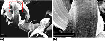
Short ribbon chips were generated in Exp. 6. A carbide bit was used in this experiment. No light emission was observed in this experiment eliminating the possibility of surface oxidation. Unfavorable machining conditions resulted in clogging of chips. Chip clogging caused greater fluctuation in moment as was observed in this experiment. As a result, ribbon chips, wrapping themselves around the shank, were formed as shown in Fig. 6.
Scanning electron microscope image showing short ribbon chip (a) general view of chip profile, (b) close up view of the box shown in Fig. 6(a) indicating built-up edges.

E. Short spiral
This chip morphology was observed in Exp. 5. This type of chip morphology is considered as the most perfect case for chip removal in drilling applications. Reference Batzer, Haan, Rao, Olson and Sutherland16 The two major motions contributing to the creation of spiral chips are rotation motion on the chip axis and axial motion along the drill flute. Reference Ke, Ni and Stephenson17 The chip surface was found to be smooth as can be seen in Fig. 7. Smooth chip movement in flute affects the chip length. Smoothness is affected by the drill point angle, the flute helix angle, and the flute size. Some saw-tooth and built-up edges formation can also be noticed in Fig. 7(b).
Scanning electron microscope image showing short spiral chip (a) general view of the chip profile at low magnification, (b) close up view of the rectangular box in Fig. 7(a) showing smoothness of the surface.

VII. QUICK STOP CONDITIONS
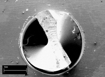
In Exp. 4, the carbide drill bit was used at 1.25-mm/min feed rate and 2500 rpm. The drill broke down during experimentation without drilling a single complete hole. The drill breakage resulted in stoppage of the drilling process. A long ribbon chip profile was observed in this case while no light was emitted under these conditions. As explained earlier, the long ribbon chip profile being thick does not break apart when it contacts the tool. This chip clogged into the incomplete drilled hole and caused larger forces to be exerted on the workpiece. As a result, the bit was broken down. Figure 8 shows the front portion of the bit stuck in the hole.
Scanning electron microscope image showing choking of the drill bit front portion hole during Exp. 4.

VIII. BURR FORMATION
In most of the drilling process, a burr is created at the entrance and exit of the hole surface. Both side burrs vary in size and are point of concern specially the exit burr, which is larger in size. Burr has been a widely recognized problem to the industry as it ruins the design integrity of the part and requires additional processes to fix it. Factors influencing the burr formation are material properties, drill geometry, and cutting conditions. Reference Dornfeldl, Kim, Dechow, Hewson and Chen18,Reference Ko and Lee19 In this study, these factors were considered to analyze the burr formation. Two different drill bits were used to observe difference in burr formation.
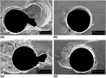
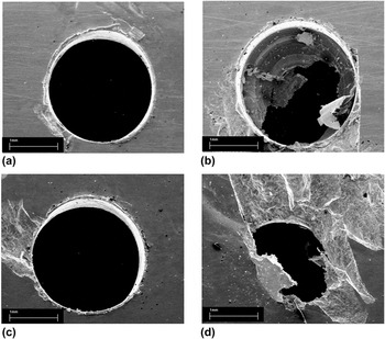
In this experimental work, the HSS drill bit was used in Exp. 1–3 under different operating parameters listed in Table II. Figure 9 shows the entrance and exit burrs formed in Exp. 2 and 3 to show the effect of spindle speed. In Exp. 2, a small amount of roll-over burr can be seen [Fig. 9(a)]. The amount of the material extruding outside the hole surface is larger than that was in Exp. 3. This is because of the melting of the work material due to high temperature caused by high spindle speed and buildup of the molten debris during chip ejection. The size of the exit burr in Exp. 2 could not be analyzed because the portion of the workpiece was chipped off as evident in Figs. 9(c) and 9(d).
Scanning electron microscope image showing entry burr when using HSS tool at 1.5 mm/min feed rate and spindle speeds of (a) 1500 rpm (Exp. 2), (b) 1000 rpm (Exp. 3) and the corresponding exit burr (c) 1500 rpm (Exp. 2), (d) 1000 rpm (Exp. 3).

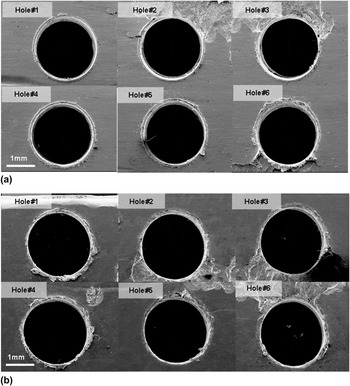
In Exp. 1, six holes were drilled under the same operating conditions. Figure 10(a) shows the entry burr formation. Starting from the first hole to the last, a small increase in the size of burr formation can be observed. More roll over can be seen because of the high temperature association. The first hole shows uniform deposition of molten debris at entry, whereas other holes show formation of some built-up edges. Exit burr of the first hole is comparatively larger than others as can be observed in Fig. 10(b).
Scanning electron microscope image showing (a) entry burr and (b) exit burr for 6 different holes drilled in Exp. 1.

In Exp. 4–6 for which the carbide drill bit was used, as discussed earlier, no light emission was observed in any experiment. As there was no light emission, less heat was generated, which results in small entry and exit burrs as can be seen in Figs. 8 and 11.
Scanning electron microscope image showing entry size and burrs in: (a) Exp. 5, (b) Exp. 6 and corresponding exit size and burrs in (c) Exp. 5 and (d) Exp. 6.

Figures 8 and 11(b) show that the carbide tool should not be used at low feed rate and at low spindle speed. At low speed, the carbide tool generates poor surface finish, creating built-up edges and molten debris get clogged inside the hole. As a result, choking of the tool or even its failure might occur. Entrance quality of Exp. 5 performed at a relatively low feed rate (1.5 mm/min) and a medium spindle speed (1500 rpm) was good in comparison to all other experiments performed as evident in Fig. 11(a). In this case, only a small amount of molten debris was observed around the entry hole. Due to high thermal conductivity of the tool material, less heat was transferred to the chip. As a result, less molten debris was formed around the entry hole. Exit burrs formed using the carbide tool was not as large as in the case of the HSS tool as shown in Figs. 11(c) and 11(d).
IX. CONCLUSION
In this work, light emission, chip morphology, and burr formation during drilling of Zr-based BMG were investigated using carbide and HSS tools. Drilling was performed by varying spindle speed and feed rate. Light emission was observed in all experiments which were performed using HSS drill bits, whereas no light emission was observed in the case of carbide tool. The quick stop condition was obtained using a carbide tool at a lower feed rate. It was also observed that at the same feed rate of 1.5 mm/min, the increase in spindle speed triggers light emission, whereas at a low feed rate (1.25 mm/min), too high spindle speed (2500 rpm) results in extensive light emission. Therefore, BMG drilling is not recommended at lower feed rates. Short spiral chip morphology, which is considered ideal in the drilling process, was observed at relatively low feed rate (1.5 mm/min) and medium spindle speed (1500 rpm). In this case, only a small amount of molten debris was observed around the entry hole. The exit burr was found to be larger as compared to the entry burrs.