I. INTRODUCTION
Self-organized TiO2 nanotube arrays grown by facile anodic oxidation of Ti foils have attracted wide interest due to their great potential in energy- and environment-related applications, such as dye-sensitized solar cells,Reference Kim, Roy, Lee and Schmuki1–Reference Sauvage, Di Fonzo, Bassi, Casari, Russo, Divitini, Ducati, Bottani, Comte and Graetzel3 pollutant degradation,Reference Wang, Hu, Hu, Yu, Xia, Zhou and Liu4 water photosplitting,Reference Hamedani, Allam, Garmestani and El-Sayed5, Reference Wang, Wang, Ling, Tang, Yang, Fitzmorris, Wang, Zhang and Li6 lithium-ion batteries,Reference Ortiz, Hanzu, Djenizian, Lavela, Tirado and Knauth7 supercapacitors,Reference Salari, Aboutalebi, Konstantinov and Liu8 and smart windows.Reference Ghicov, Alba, Macak and Schmuki9–Reference Hahn, Ghicov, Tsuchiya, Macak, Munoz and Schmuki11 To further improve their performance and diversify their functionalities, anodic TiO2 are often used as host for other substances, e.g., metals, semiconductors, or polymers. For example, nickel oxide-embedded TiO2 nanotube arrays have been utilized as anode materials for lithium-ion batteries.Reference Xie, Zhou, Huang, Huang and Lu12 Anodic TiO2 nanotubes decorated with CdS nanoparticles are shown with efficient solar light harvesting in the visible light region with an 8- to 9-fold of enhancement in photoactivity compared with pristine TiO2nanotubes.Reference Banerjee, Mohapatra, Das and Misra13
Foreign species are generally introduced to anodic TiO2 by hydrothermal treatments,Reference Zhang, Bang, Tang and Kamat14 dip coating,Reference Kontos, Likodimos, Stergiopoulos, Tsoukleris, Falaras, Rabias, Papavassiliou, Kim, Kunze and Schmuki15 chemical vapor deposition,Reference Hesabi, Allam, Dahmen, Garmestani and El-Sayed16 or electrodepositionReference Macak, Gong, Hueppe and Schmuki17 to form nanocomposites. Among various fabrication methods, electrodeposition is particularly attractive due to its simplicity and convenience, as demonstrated by the pioneering studies. For example, Schmuki et al.Reference Macak, Gong, Hueppe and Schmuki17 have developed a facile self-doping electrodeposition technique to deposit Cu nanorods inside the anodic TiO2 nanotube array. Choi et al.Reference Seabold, Shankar, Wilke, Paulose, Varghese, Grimes and Choi18 have used alternating soaking and electrodeposition treatments to achieve high loading of CdTe nanoparticles inside the TiO2 nanotubular structures. Wang et al.Reference Wang, Ye, Yu and Zhou19 successfully electrodeposited polypyrrole into the TiO2nanotube arrays to form p–n heterojunctions.
To our knowledge, anodic TiO2-based nanocomposites fabricated by electrodeposition can be generally divided into two groups: (i) foreign species mainly deposited on the film surface with the tube openings covered and (ii) foreign species mainly filled inside the nanotubes as nanorods or nanowires and often with the intertubular voids also filled. For the first group, the large surface of TiO2 nanotubes cannot be effectively accessed. For the second group, the bowl-shaped bottoms of the TiO2nanotubes form an oxide barrier for charge transportation between the foreign species inside the tube and the Ti substrate.
To bypass the above-mentioned two obstacles, this study presents a novel type of anodic TiO2-based nanocomposite fabricated by filling the foreign species only into the intertubular voids while leaving the tube inside unfilled. Compared to the structures with metals loaded inside the tubes, one major advantage of having metals loaded outside the tubes is that electrons can transfer more easily to the conductive substrate by bypassing the thick oxide layer at the nanotube bottoms. This way, charge can be more readily transferred between the foreign species and the Ti substrate, and meanwhile, a large portion of the nanotube surface is kept accessible by the environment. To our knowledge, this type of TiO2-based nanoarchitecture has not been constructed by any method. Here, in this study, a facile electrodeposition method is developed to selectively deposit metals into the intertubular voids of the anodic TiO2nanotubes.
TiO2 is widely used as photocatalysts.Reference Macak, Zlamal, Krysa and Schmuki20 When TiO2 was illuminated with photons with energy greater than its band gap, electrons in the valence band can be excited to the conduction band, creating electron–hole pairs [Eq. (1)]. The photogenerated electrons and holes then react with water or oxygen to form highly reactive intermediates, such as hydroxyl radical (·OH) or superoxide species (O2−) [Eqs. (2) and (3)], which can further degrade organic molecules to carbon dioxide and water.Reference Harvey, Rudham and Ward21–Reference Liu, Wang, Yang, Cheng and Lu24 However, in most instances, the photogenerated electrons and holes can easily recombine, resulting in lowered photocatalytic efficiencies. A common solution to prevent charge recombination is to enable rapid charge separation by forming the Schottky barriers between TiO2 and specific metal species. Metals in the Schottky barriers help to capture the photogenerated electrons and prevent them from flowing back to TiO2. Previous studies have shown that metal/TiO2 nanocompositesReference Zhang25–Reference Iliev, Tomova, Bilyarska and Petrov33 (such as Ni/TiO2 nanocomposites,Reference Zhang25, Reference Tayade, Kulkarni and Jasra26 Pt–TiO2 coaxial nanotubes,Reference Chen, Chen, Quan, Yu, Zhao and Zhang27 and TiO2 nanotubes loaded with Ag and Au nanoparticlesReference Xie, Sun, Wang, Lai, Wang, Chen and Lin28, Reference Paramasivam, Macak and Schmuki29) display improved photocatalytic performance comparing to the pristine TiO2 counterparts, mainly due to the Schottky barriers formed between metals and TiO2:
 $${\rm{TiO}}_2 \, + \,{\rm{h}}^ + \to {\rm{e}}^ - \, + {\rm{h}}^ +\quad ,$$
 $${\rm{H}}_2 {\rm{O}}\, + \,{\rm{h}}^ + \to \,\cdot {\rm{OH}}\, + \,{\rm{H}}^ + \quad,$$
 $${\rm{O}}_2 \, + \,{\rm{e}}^ - \to {\rm{O}}_2^ -\quad .$$
In this work, the fabricated novel Ni/TiO2 nanocomposites show significantly improved photocatalytic efficiency than the pristine nanotubes in degrading organic dye molecules. The observed improvement in photocatalytic efficiency is ascribed to the Schottky barriers formed between Ni and TiO2.
II. MATERIALS AND METHODS
A. Fabrication of TiO2 nanotube arrays
TiO2 nanotubes were prepared by electrochemical anodization of a Ti foil. The anodization experiments were carried out at ∼25 °C. A two-electrode configuration was used for anodization. The Ti substrates (0.25-mm thick, 99.7% purity; Sigma-Aldrich, Kowloon, Hong Kong) were ultrasonically cleaned in acetone, ethanol, and water successively and then dried in a nitrogen stream before anodization. The foil was then pressed together with an Al foil against an O ring in the electrochemical cell (leaving 1.2 cm2exposed to the electrolyte). The Al foil connected to the external circuit was used as a back contact for the Ti substrate. A Pt wire ring was used as the counter electrode. The electrolyte used was a dimethyl sulfoxide (99.9%; Advanced Technology & Industrial Co., Ltd., Kowloon, Hong Kong) solution of 2.0 wt% HF (48%, Sigma-Aldrich). Anodization was carried out at 40 V for 10 h with a computer-controlled Keithley 2400 SourceMeter (Kowloon, Hong Kong).
B. Electrodeposition of Ni
Electroplating of Ni was carried out at room temperature (∼25 °C) using a three-electrode system with the as-anodized TiO2 nanotubes as the working electrode, a Pt ring as the counter electrode, and a saturated calomel electrode as the reference electrode. The electrolyte consisted of 1.0 M NiCl2·6H2O, 0.6 M H3BO3, and 0.2 mg/mL saccharin. Saccharin was usually added in the electroplating electrolyte as a grain refiner or a brightener for nanocrystalline Ni electrodeposition.Reference Moti, Shariat and Bahrololoom34 Electrodeposition was performed with a periodic pulsed current waveform with each period having three steps (−200 mA/cm2 for 10 ms, 200 mA/cm2 for 4 ms, and 0 mA/cm2 for 1 s successively). Pulsed electroplating current was used because it promotes even nucleation and film growth on the substrate so that Ni can be deposited in a more uniform manner. After electrodeposition, the sample was rinsed with deionized water and dried under a stream of N2. For comparison, Ni deposition was also carried out using thermally annealed anodic TiO2nanotubes (450 °C for 3 h in air) as the working electrode.
C. Thermal treatment
For photocatalytic measurements, the Ni-deposited TiO2 nanotubes were thermally annealed at 450 °C for 3 h in a N2atmosphere beforehand.
D. Photocatalytic degradation test
Photocatalytic efficiency was tested by immersing the sample of interest into an aqueous solution of 2.0 × 10⁻⁵ M methyl red (MR). The working area of the sample was 0.6 × 0.6 cm. A high pressure mercury lamp with maximum output wave length at 365 nm was used as the illumination source. The illumination intensity was 20 mW/cm2, measured at the sample surface using a UVX digital radiometer. The absorption changes of MR were monitored by measuring the maximum absorption at 526 nm using a ultraviolet (UV)–vis spectrometer (Agilent UV-8453).
III. RESULTS AND DISCUSSION
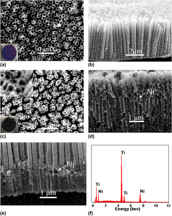
As-anodized TiO2 nanotube arrays were used as templates for Ni deposition. SEM studies (Fig. 1) show that the as-anodized TiO2 nanotubes have an average diameter of 200 nm and stand vertically to the substrate, forming a self-ordered structure. The fabricated TiO2 nanotubes are ∼5 μm long with an aspect ratio of ∼25 and a density of 1.8 × 10⁹/cm2. A comparison of the film morphologies before and after Ni deposition clearly shows that the intertubular voids were filled with foreign species, which was further confirmed to be Ni by EDX [Fig. 1(f)] and XRD (Fig. 2) studies. The atomic ratio of Ni in the as-deposited Ni/TiO2 nanocomposite is ∼14%. Figure 1(d) shows that the lower part of electrodeposited Ni nanostructures took the form of a continuous compact structure filling up the intertubular voids, whereas the upper part gradually turned from compact structure into disconnected nanoparticles with an average diameter of 70 nm near the top surface. A closer examination of the sample morphology at a short deposition time [e.g., 1000 s, Fig. 1(e)] reveals that Ni was filled up from the bottom of the intertubular voids. Moreover, the tube inside was kept empty [Fig. 1(c) inset and Fig. 1(e)] and a clean sample surface was observed with the most tube openings left unclogged [Fig. 1(c)]. These structural characteristics proved to be advantageous in the application studies that we will discuss in the later part of this paper.
(a–b) Top view and cross-sectional SEM images of the as-anodized TiO2 nanotube array; (c–d) the Ni/TiO2 nanocomposite films fabricated using as-anodized TiO2nanotube array with the Ni deposition time of 3600 s; and (e) 1000 s. (f) The EDX spectrum was taken from the film shown in (d). Optical photographs of the as-fabricated films (film diameters ∼1.3 cm) on Ti are shown in the insets of (a) and (c).

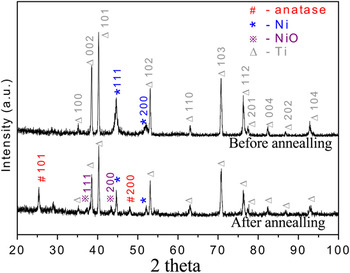
XRD patterns of Ni/TiO2nanocomposites before and after thermal annealing.

We emphasize here that the TiO2 nanotube templates were not thermally treated beforehand. By contrast, the majority of electrodeposited anodic TiO2 nanocomposites previously reported used thermally annealed TiO2 nanotubes as template.Reference Wang, Yin, Zhang and Gao35, Reference Zhang, Yang, Xiao, Zhang, Lu and Li36 Taking Ni-deposited anodic TiO2 nanotubes as one example, in one previous study where DC voltage was used, nearly, all deposition took place on the film surface forming a Ni layer, whereas in another study where pulsed current was used, most of the Ni was deposited on the film surface and a small portion deposited inside the tubes.Reference Wang, Yin, Zhang and Gao35, Reference Zhang, Yang, Xiao, Zhang, Lu and Li36 The difference between these previously reported morphologies and the one in this study clearly suggests that the thermal pretreatment of the anodic TiO2 templates has a strong impact on the growth mechanism of metal/anodic TiO2nanocomposites.
It is helpful to point out when porous films with high aspect ratio pores (e.g., the nanotubes or the intertubular voids) are used as templates, whether metal electrodeposition will take place on the film top surface or from the bottom of the pores are mainly affected by two competing factors: (i) difference in electric field between film top surface and pore bottoms, which is strongly affected by the conductivity of the film, the more insulating the film, the more likely metals are deposited on the bottom of the pores; and (ii) the diffusion rate of the ions through the high aspect ratio pores, which determines how efficient the consumed ions can be replenished inside the pores. Here, in this study, the porous template used for electrodeposition is an array of well-separated TiO2nanotubes. Notably, the intertubular voids form a continuous space open to the electrolyte solution and are much more spacious than the isolated space inside the nanotubes. This specific template morphology facilitates much faster ion diffusion through the intertubular voids than inside the tube and thus promotes metal electrodeposition outside the nanotubes.
Previous studies show that the as-anodized TiO2 nanotubes are amorphous and poor electrical conductors.Reference Fang, Liu, Wang, Sun, Guan, Li, Zhou, Sham and Cheng37 Furthermore, it should be pointed out that there exists a thin layer of amorphous oxide at the bottom of the intertubular voids. The conductivity study of this thin oxide layer has not been reported in literature. From the bottom view SEM image of the anodic TiO2 film stripped off the Ti substrate (Fig. S1), a thin oxide layer at the bottom of the intertubular voids was observed. Moreover, the thickness of this oxide layer appeared to be much thinner than the bottoms of the TiO2 nanotubes. Thus, the bottoms of the intertubular voids are possibly more conductive than the bottoms of the nanotubes where a bowl-shaped oxide barrier layer lies between the electrolyte and the Ti substrate and competes more favorably for electrodeposition to take place. Therefore, when as-anodized TiO2 nanotubes are used as host, electrodeposition will first take place from the bottom of the intertubular voids and grow upwards. On the other hand, thermal annealing turns the poorly conductive amorphous TiO2 nanotubes into more conductive crystalline TiO2nanotubes, as commonly observed in previous studies. Moreover, thermal annealing in air can readily thicken the oxide on the bottom of the intertubular voids, diminishing the conductivity difference between the bottoms of the intertubular voids and the nanotubes. Therefore, when thermally annealed nanotube arrays are used as host, electrodeposition is more likely to take place either at the template surface or inside the template but without selectivity between inside and outside the nanotubes.
The above reasoning was further verified by a control experiment with a thermally annealed TiO2nanotube array used as host for Ni electrodeposition. Ni was electrodeposited both inside and between the nanotubes with the film top surface severely clogged (Fig. S2). The nanocomposite thus obtained was a fairly dense structure with low porosity.
Notably, for most practical applications, anodic TiO2 needs to be thermally annealed to transform it from amorphous phase to anatase phase.Reference Macak, Zlamal, Krysa and Schmuki20 For the novel Ni/TiO2 nanocomposites developed in this study, we further thermally treated them in a nitrogen atmosphere for the downstream application studies. X-ray diffraction measurements (Fig. 2) clearly show that Ni was present in the as-fabricated nanocomposite and most of the deposited Ni was not oxidized after the thermal treatment, whereas the phase of the TiO2 component changed from amorphous to anatase by thermal treatment (Fig. 2). No preferred orientation of Ni and TiO2was observed from the XRD patterns.
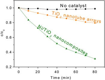
In this study, photocatalytic experiments were carried out to evaluate the effectiveness of the fabricated Ni/TiO2 nanocomposites for degrading MR, which is a nonbiodegradable dye that is commonly used in textile and paper industrials. For comparison, pristine TiO2 nanotube arrays were also tested. Both of the two samples were annealed in N2 before the photocatalytic experiments to transform it to anatase structure. Control experiment (in absence of any photocatalyst) revealed that the dye degradation under UV illumination was almost negligible. From the results (Fig. 3), the photocatalytic efficiency of the Ni/TiO2nanocomposites is significantly higher than the pristine nanotubular counterparts.
Ratio of the actual and initial concentrations (c/c 0) of MR as a function of the UV illumination time. The photocatalysts used were 5-μm-thick anodic TiO2films with and without Ni deposition. The control experiment was carried out in absence of any photocatalyst (“No catalyst”).

Planar Ni is well known for its lack of photocatalytic ability under UV illumination.Reference Zhang25 The higher efficiency observed on Ni/TiO2 nanocomposites is attributed to the fast separation of photogenerated electron–hole pairs through the formation of a Schottky barrier between TiO2 and Ni, in good agreement with the previous reports on metal/TiO2 nanocomposites where the Schottky barriers are formed.Reference Zhang25–Reference Iliev, Tomova, Bilyarska and Petrov33 A Schottky junction is a metal–semiconductor junction, which has rectifying characteristics, suitable for use as a diode. During the photocatalytic process, how well the photogenerated electron–hole pairs can be prevented from recombining largely determines how good the photocatalytic performance of TiO2 is. Because Ni has a higher work function (5.04–5.35 eV) than TiO2, Ni–TiO2 forms the Schottky heterojunction, which provides a one-way traffic for electrons to transport from TiO2 to Ni but serves as a barriers for holes, greatly suppressing the recombining process of charge carriers. In aqueous solution, the photocatalytic decomposition mechanism of organic molecules is mainly attributed to oxidation directly by the photogenerated holes or by the hydroxyl radicals produced from the photogenerated holes.Reference Chen, Ollis, Rulkens and Bruning38 Therefore, a high density of photogenerated holes in the photocatalyst is beneficial for enhancing its photocatalytic efficiency. In our Ni/TiO2 system, due to the existence of the Schottky barrier, the photogenerated electrons tend to be captured by the Ni side, making more photogenerated holes available on the TiO2 side and facilitating photooxidation of organic molecules. The electrons in Ni were possibly transferred to the H+ ions or O2 molecules in the aqueous solution to form H2 or O2− radicals. Moreover, the clean top surface of the fabricated Ni/TiO2 nanostructure with the tube openings unclogged ensures the easy accessibility to the tube inside walls by the dye molecules. The considerable open porosity of the Ni/TiO2 nanocomposite is also beneficial for UV light absorption. Finally, the nanocomposites reported here feature a continuous metal framework formed by intertubular Ni and a coaxial morphology with each individual TiO2 nanotube wrapped with nanostructured Ni, providing a large Schottky contact area between TiO2 and Ni. Regarding the light absorption by Ni in the fabricated Ni/TiO2 nanocomposites, bulk Ni has a much higher light absorption in the UV to near-infrared region (over 50% for the UV light), while nanostructured Ni is very likely to be more absorptive than bulk Ni. Therefore, upon UV illumination during the dye photodegradation test, the Ni-deposited TiO2 nanotubes possibly had a higher temperature than the pristine counterparts. The increased light absorption and resultant temperature rise are likely other factors responsible for the observed higher photocatalytic efficiency on the Ni-deposited TiO2nanotubes.
IV. CONCLUSION
Ni/TiO2 coaxial nanotubular structures have been successfully achieved by selectively depositing Ni between the intertubular voids of anodic TiO2 nanotube arrays that are prepared by electrochemical anodization of a Ti foil. It was found that the application of as-anodized nanotubes rather than thermally annealed nanotubes as the host is the key to achieve the desired structures. Further studies on photodegradation of MR reveal that the fabricated Ni/TiO2 coaxial nanostructures with Ni wrapping around the TiO2 nanotubes possess improved photocatalytic efficiency, comparing to the pristine nanotube counterparts. The reason for the observed improvement in photocatalytic efficiency is attributed to the Schottky barriers formed between Ni and TiO2.
ACKNOWLEDGMENT
This work was supported by City University of Hong Kong (Projects 9667056 and 7002741).