1. Introduction
For many years, the passive (non-driven) motion joint has drawn significant attention in industry and a broad range of applications, such as automobile drivetrains, aircraft control mechanisms, machine tools, and parallel manipulators (PMs). In the field of PM, the joint used to connect the mobile platform, active (driven) motion legs, and a fixed platform are critical components used primarily for power transmission and steering. PM has been a research hotspot since Stewart invented the most famous PM in 1965 [Reference Stewart1]. The PM workspace is an essential index for judging the performance of PM [Reference Xie, Liu and Wang2, Reference Yang, Shao and Shin3], and the joint workspace had a significant impact on the PM workspace [Reference Cao, Huang, Zhou and Ji4–Reference Merlet7]. Hence, a comprehensive understanding of the precise calculation method of the joint workspaces is crucial in designing a performance-based strategy for PMs.
Researchers initially used spherical joints or universal joints as passive motion joints. Zhang et al. [Reference Zhang, Du and To8] considered the interference between the upper and lower joints and analyzed the universal-joint workspace. In recent years, researchers have used offset joints to replace them in PM, primarily because offset joints have a larger workspace. Since the introduction of offset parameters in the offset joint, compared with the universal joint, the analysis of the offset-joint workspace is more complex. Therefore, this is only an empirical judgment, not a theoretical one.
Furthermore, traditional spherical and universal joints have the disadvantages of low stiffness and being prone to manufacturing and installation errors, while offset joints can avoid these [Reference Großmann and Kauschinger9, Reference Rainer and Brian10]. Grossmann and Kauschinger [Reference Großmann and Kauschinger9] proposed three types of offset joints and found that the rotation range of an offset joint is wider than that of a universal joint. Gloess and Lula [Reference Rainer and Brian10] improved the stiffness of PM by adopting offset joints to replace the traditional universal joints. Based on calculations, the offset joint has more than two times greater stiffness than the traditional universal joint.
Since the mechanical properties of the offset joint were calculated through experiments, theoretical analyses, and CAD simulations, the PM using offset joints has had many applications, such as bone-surgery operation [Reference Hung, Hsu, Ho, Chi and Yen11] and large-diameter telescopes precisely adjustment [Reference Han, Zhang, Zhang, Han, Li and Xu12], because of its greater precision, workspace, and carrying capacity. Hu and Lu [Reference Hu and Lu13] and Ji and Wu [Reference Ji and Wu14] proposed a three-degrees-of-freedom (3-DOF) PM with offset joints and analyzed the PM’s kinematics, singularity, and workspace. When a 6-DOF PM with offset joints is involved, the mathematical motion model is more complex, and there is no analytical method to solve kinematics. The Denavit–Hartenberg (D-H) method is used to solve inverse kinematics [Reference Zhang, Han, Xu, Han, Yu, Mao and Wu15–Reference Dalvand and Shirinzadeh17] and acceleration [Reference Zhang, Han, Zhang, Xu, Xiong, Han and Li18] of the complex PM with offset joints. Morell et al. [Reference Morell, Tarokh and Acosta19] solved the forward kinematics of a 6-RRCRR PM with offset joints using machine learning.
Although most of the previous studies investigated PMs that use offset joints through theoretical analysis, numerical analysis, and experiments, a theoretical analysis framework does not exist to calculate the offset-joint workspaces and evaluate the influence of the offset amount of the offset joints on the workspace. Thus, this paper aims to present a theoretical analysis framework to determine the offset-joint workspaces and theoretically evaluate the influence of the offset amount of the offset joints on the workspace.
The remainder of this paper is organized as follows. The theoretical framework of the offset-joint workspaces is described in Section 2. In Section 3, the influence of the offset amount of the offset joints is explored, and in Section 4, the PM workspace using different joint types is studied. Finally, the conclusions are summarized in Section 5.
2. Workspace model development
2.1. Description of axial offset joint
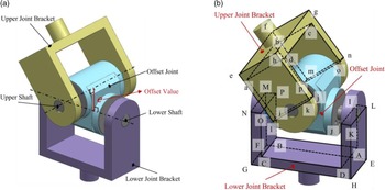
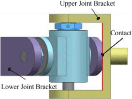
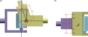
The model for an axial offset joint is presented, and the axial offset e of this structure is depicted in Fig. 1(a). The offset joint consists of the upper-joint bracket, the offset joint, and the lower-joint bracket, in which the two shafts of the offset joint do not intersect but have an axial offset in space. When the joint is moving, the upper-joint bracket rotates around the upper shaft, and the lower-joint bracket rotates around the lower shaft. Therefore, the joint is a 2-DOF RR series chain.
As illustrated in Fig. 1(b), geometric feature points represent the geometric features of the joint. Uppercase letters are used to describe the lower-joint bracket, while lowercase letters the upper-joint bracket to distinguish the upper and lower-joint brackets of the offset joint. The shape and size of the two brackets are the same, and the geometric parameters of the joint are listed in Table I.
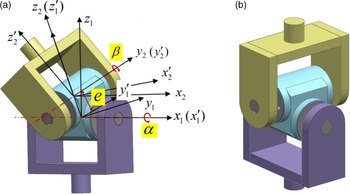
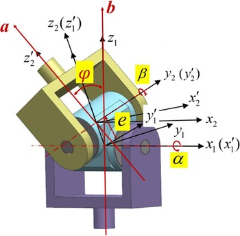
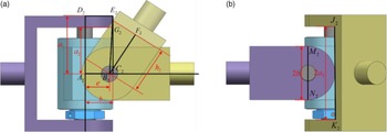
As depicted in Fig. 2(a), four Cartesian coordinate systems are required to describe the offset-joint workspace. These four coordinate systems
 $O_{1}-x_{1}y_{1}z_{1}, {O^{\prime}_{1}}-{x^{\prime}_{1}}{y^{\prime}_{1}}{z^{\prime}_{1}}, O_{2}-x_{2}y_{2}z_{2}$
, and
 ${O^{\prime}_{2}}-{x^{\prime}_{2}}{y^{\prime}_{2}}{z^{\prime}_{2}}$
, are placed in the lower-joint bracket, lower shaft, upper shaft, and upper-joint bracket of the offset joint. These coordinate systems are used to represent the position of the parts of the offset joint during rotation. It is worth noting that these coordinate systems are not the DH parameter but rather are used solely for the purpose of visualizing the rotation of the offset joint. Each coordinate system moves with the motion of the connected parts. The coordinate system
 $O_{1}-x_{1}y_{1}z_{1}$
is the global coordinate system, and the other three coordinate systems
 ${O^{\prime}_{1}}-{x^{\prime}_{1}}{y^{\prime}_{1}}{z^{\prime}_{1}}, O_{2}-x_{2}y_{2}z_{2}, {O^{\prime}_{2}}-{x^{\prime}_{2}}{y^{\prime}_{2}}{z^{\prime}_{2}}$
can be obtained by rotation and translation of the coordinate system
 $O_{1}-x_{1}y_{1}z_{1}$
. For convenience, the angle of the lower-joint bracket is defined relative to the lower shaft as α, the angle of the upper-joint bracket relative to the upper shaft as β, and the offset quantity of the offset joint as e. The angles α and β are the offset joint’s two independent rotation DOF and represent the possible rotation range of the offset joint. The zero-reference for the rotation angles α and β of the offset joint is defined as the initial position of the joint, which is illustrated in Fig. 2(b). In particular, α represents the rotation angle of the lower-joint bracket relative to its initial position, while β represents the rotation angle of the upper-joint bracket relative to its initial position.
Geometric parameters of offset joint.

(a) 3D model of axial offset joint and (b) its geometric feature points.

(a) Coordinate system of offset joint and (b) its zero-reference position.

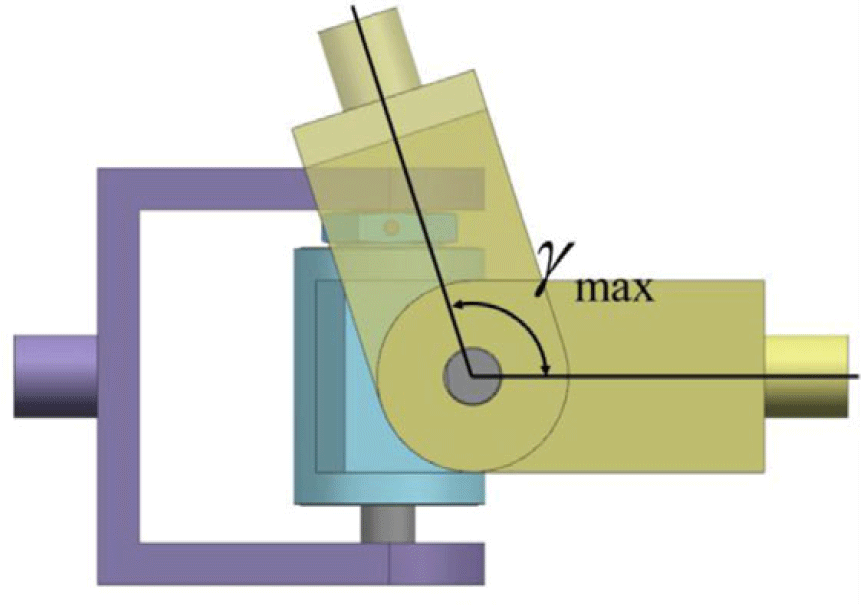
Given the different joint bracket sizes, the offset joints can be divided into two categories, as presented in Table II. The limitations of the two types of offset joints are detailed in Appendix A. Different methods are required to solve the workspace of different types of offset joints. The theoretical framework of the joint to determine the interference curve of these two types of offset joints and investigate the workspace is presented in this section.
Joint type based on maximum rotation range (
 $\gamma _{\max }$
).

2.2. Interference curve of axial offset joint
2.2.1. Offset joint
 $\gamma _{\max }\gt 90^{\circ}$

In calculating the offset-joint workspace
 $\gamma _{\max }\gt 90^{\circ}$
, as presented in Table II(a), the interference motion curve of the joint is described by its two independents rotation angles α and β. Because the structure of the joint is centrosymmetric, the interference curve between the two included angles can be divided into four sections (
 $\alpha \gt 0, \beta \gt 0$
and
 $\alpha \lt 0, \beta \gt 0$
and
 $\alpha \lt 0, \beta \lt 0$
and
 $\alpha \gt 0, \beta \lt 0$
). Therefore, the interference curve can be obtained only by calculating one section (
 $\alpha \gt 0, \beta \gt 0$
) of the interference curve.
In describing the interference curve of the offset joint, three angles are defined to determine the characteristic pose of the offset joint as follows (refer to Appendix B for details on these three angles):
 \begin{equation} \gamma _{1}=\frac{\pi }{2}+\arccos \!\left(\frac{a_{1}}{\sqrt{b^{2}+h_{2}^{2}}}\right)-\arccos \!\left(\frac{h_{2}}{\sqrt{b^{2}+h_{2}^{2}}}\right) \end{equation}
 $\gamma _{1}$
is the maximum achievable rotation angle of the bracket with respect to the offset joint.
 \begin{align} \gamma _{2}& =\arccos \frac{b}{\sqrt{a_{2}^{2}+\left(b-e\sin \!\left(\gamma _{1}\right)\right)^{2}+\left(h_{2}+e\cos \!\left(\gamma _{1}\right)\right)^{2}-a_{1}^{2}}} \nonumber \\ & \quad -\arccos \frac{a_{2}}{\sqrt{a_{2}^{2}+\left(b-e\sin \!\left(\gamma _{1}\right)\right)^{2}+\left(h_{2}+e\cos \!\left(\gamma _{1}\right)\right)^{2}-a_{1}^{2}}} \end{align}
 $\gamma _{2}$
is the maximum angle of rotation of the bracket relative to the offset joint when one edge of the other bracket contacts the side of the bracket.
 \begin{equation} \gamma _{3}=\frac{\pi }{2}-\arctan \!\left(\frac{b-e}{a_{2}}\right)-\arctan \!\left(\frac{b}{\sqrt{a_{2}^{2}+\left(b-e\right)^{2}-b^{2}}}\right) \end{equation}
 $\gamma _{3}$
is the maximum rotation angle of the bracket relative to the offset joint when the rotation angle of the other bracket relative to the offset joint is
 $\pi /2$
. Under this position, the axis of the upper and lower-joint brackets is perpendicular.
As illustrated in Table III, the offset joint has six characteristic poses at each one-fourth motion boundary, obtained from the above three angles. Each two adjacent characteristic poses constitute a motion process. The offset joint starts to move from the first characteristic pose, stops at the sixth characteristic pose, and passes through the other four characteristic poses during this motion. Therefore, according to the six characteristic poses, the motion process can be divided into five segments, where each stage motion represents a continuous motion state of the offset joint. Moreover, the motion process can be represented with two independent rotational angles, α and β. The derivation of the theoretical formula of the five-stage interference motion is presented in Appendix C.
Offset joint interference curve for
 $\gamma _{\max }\gt 90^{\circ}$
.

2.2.2. Offset joint
$\gamma _{\max }\lt 90^{\circ}$

In calculating the offset joint
 $\gamma _{\max }\lt 90^{\circ}$
, as presented in Table II(b), the offset joint is widely used for the volume limitation of the 6-DOF PM because of its small volume. The research method is the same as the offset joint
 $\gamma _{\max }\gt 90^{\circ}$
. However, the difference is that the motion process of the offset joint
 $\gamma _{\max }\lt 90^{\circ}$
is relatively simple, as presented in Table IV. The offset-joint workspace can be described accurately by only defining a maximum rotation angle
 $\gamma _{\max }$
.
Offset joint interference curve for
 $\gamma _{\max }\lt 90^{\circ}$
.

The interference motions equations of the two types of offset joints represent the continuous motion states of the joints, which can accurately calculate the range of rotation of the joints.
2.3. Workspace of axial offset joint
The included angle between the upper and lower-joint bracket rods of the offset joint, which is the offset joint’s workspace
 $\varphi$
, can be calculated based on the resulting offset joint’s interference motion curve, as depicted in Fig. 3. The angle of the lower shaft is defined relative to the lower-joint bracket as α and the angle of the upper-joint bracket relative to the upper shaft as β. The four coordinate systems
 $O_{1}-x_{1}y_{1}z_{1}, O^{\prime}_{1}-x^{\prime}_{1}y^{\prime}_{1}z^{\prime}_{1}, O_{2}-x_{2}y_{2}z_{2}, O^{\prime}_{2}-x^{\prime}_{2}y^{\prime}_{2}z^{\prime}_{2}$
are connected to the lower-joint bracket, the axis of the lower shaft, the axis of the upper shaft, and the upper-joint bracket. The coordinate system
 $O^{\prime}_{1}-x^{\prime}_{1}y^{\prime}_{1}z^{\prime}_{1}$
is obtained by rotating the coordinate system
 $O_{1}-x_{1}y_{1}z_{1}$
by an angle of α about the
 $x_{1}$
axis. The coordinate system
 $O_{2}-x_{2}y_{2}z_{2}$
is obtained by shifting the coordinate system
 $O^{\prime}_{1}-x^{\prime}_{1}y^{\prime}_{1}z^{\prime}_{1}$
e distance along the common vertical line of the upper and lower shaft of the offset joint. Finally, the coordinate system
 $O^{\prime}_{2}-x^{\prime}_{2}y^{\prime}_{2}z^{\prime}_{2}$
is obtained by rotating the coordinate system
 $O_{2}-x_{2}y_{2}z_{2}$
by an angle of β about the
 $y_{2}$
axis. This rotation process can be described mathematically.
The position of the upper rod can be represented by vector
 $\boldsymbol{{a}}$
in coordinate system
 $O^{\prime}_{2}-x^{\prime}_{2}y^{\prime}_{2}z^{\prime}_{2}$
:
 \begin{equation} {}^{O^{\prime}2}{\boldsymbol{{a}}}{}=[\begin{array}{l@{\quad}l@{\quad}l} 0 & 0 & 1 \end{array}]^{\text{T}} \end{equation}
Vector
 $\boldsymbol{{a}}$
can be represented in coordinate system
 $O_{1}-x_{1}y_{1}z_{1}$
by coordinate transformation:
 \begin{equation} {}^{O_1}{\boldsymbol{{a}}}{} = {}^{O_1}_{O^{\prime}_1}{\boldsymbol{{R}}}{}\left({}^{O_2}_{O^{\prime}_2}{\boldsymbol{{R}}}\, {}^{O^{\prime}_2}{\boldsymbol{{a}}}{} + {}^{O^{\prime}_1}{\boldsymbol{{p}}}{_{O_2}^{}}\right)=\left[\begin{array}{c} \sin \beta \\[3pt] -\sin \alpha (\cos \beta +e)\\[3pt] \cos \alpha (\cos \beta +e) \end{array}\right] \end{equation}
where
 ${}^{O_1}_{O^{\prime}_1}{\boldsymbol{{R}}}{}=\left[\begin{array}{c@{\quad}c@{\quad}c} 1 & 0 & 0\\[3pt] 0 & \cos \alpha & -\sin \alpha \\[3pt] 0 & \sin \alpha & \cos \alpha \end{array}\right], {}^{O_2}_{O^{\prime}_2}{\boldsymbol{{R}}}{}=\left[\begin{array}{c@{\quad}c@{\quad}c} \cos \beta & 0 & \sin \beta \\[3pt] 0 & 1 & 0\\[3pt] -\sin \beta & 0 & \cos \beta \end{array}\right]$
are rotation matrices about x-axis and y-axis, respectively.
 ${}^{O^{\prime}_1}{\boldsymbol{{p}}}{_{O_2}^{}}=\left[\begin{array}{l} 0\\[3pt] 0\\[3pt] e \end{array}\right]$
represents the translational vector of coordinate system
 $O_{2}-x_{2}y_{2}z_{2}$
relative to
 $O^{\prime}_{1}-x^{\prime}_{1}y^{\prime}_{1}z^{\prime}_{1}$
.
Similarly, the position of the lower rod can be represented by vector
 $\boldsymbol{{b}}$
in coordinate system
 $O_{1}-x_{1}y_{1}z_{1}$
:
 \begin{equation} {}^{O_1}{\boldsymbol{{b}}}{}=[\begin{array}{l@{\quad}l@{\quad}l} 0 & 0 & 1 \end{array}]^{\text{T}} \end{equation}
The offset-joint workspace
 $\varphi$
which is the angle between the upper- and lower-joint brackets of the offset joint can be deduced as follows:
 \begin{equation} \varphi =\arccos \!\left(\frac{{}^{O_1}{\boldsymbol{{a}}}{}\cdot {}^{O_1}{\boldsymbol{{b}}}{}}{\left\| \left.{}^{O_1}{\boldsymbol{{a}}}{}\right\| \right.\left\| \left.{}^{O_1}{\boldsymbol{{b}}}{}\right\| \right.}\right)=\arccos \frac{\cos \alpha \!\left(\cos \beta +e\right)}{\sqrt{2e\cos \beta +e^{2}+1}} \end{equation}
Modifying the offset value can alter the workspaces for offset joints.
3. Influence of the joint offset value
An example is provided to examine the interference curve and offset joint workspace. The geometric parameters of the offset joint
 $\gamma _{\max }\gt 90^{\circ}$
and
 $\gamma _{\max }\lt 90^{\circ}$
are listed in Table V. The offset quantities of the offset joint e are 0, 5, and 10 mm.
Geometric parameters of offset joints.

Coordinate system of offset joint and workspace.

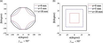
According to the five kinematics equations in Table III, the interference curve of the offset joint
 $\gamma _{\max }\gt 90^{\circ}$
can be obtained, as depicted in Fig. 4(a). According to the two kinematics equations in Table IV, the interference curve of the offset joint
 $\gamma _{\max }\lt 90^{\circ}$
can also be obtained, as depicted in Fig. 4(b).
Interference curves of offset joint with different offset values.

Figure 4 illustrates the interference curves of α and β under different offset values. These curves describe the relationship between two independent rotation angles α and β. The part enclosed by the interference curve is a rotation range of independent rotation angles α and β, in which the offset joint can rotate freely. Furthermore, Fig. 4(a) and Fig. 4(b) reveal that, with the increase in the offset value of the joint, the rotation range of the offset joint increases – both types of offset joints have the same outcome.
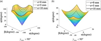
Because of the interference between the two independent rotation angles α and β of the offset joint, the surface described by the workspace equation of the offset joint is a deformed surface with four wings. As illustrated in Fig. 5, the part enclosed by the inner curve is the traditional universal joint’s workspace surface and that enclosed by the outer curve is the offset joint’s workspace surface, with offset values e of 10 and 5 mm. By comparison, the rotation range of the offset joint is wider than that of the traditional universal joint, and the increase in the offset value increases the workspace size.
Workspace of offset joint with different offset values.

4. PM workspace using various joint types
The PM’s workspace is an essential performance index. It is a set of reachable points for reference points of a mobile platform. The motion pose of the mobile platform contains six variables that need to be described by six-dimensional space, which is not conducive to graphical expression. Therefore, the overall PM workspace should be expressed by position and orientation workspaces. The position workspace is the space composed of all the positions that can be reached by the reference points of the mobile platform for a given attitude of the mobile platform. The orientation workspace is the space composed of all the orientations that the mobile platform can achieve under the condition of a given reference point position of the mobile platform. The primary main approach to solving the workspace problem is to employ the technique of discretizing points in space. This involves treating the workspace as a set composed of several discrete points, each point represents a position or an orientation. The leg length and joint rotation angle were calculated by inverse kinematics to determine whether the pose point was in the workspace.
To better illustrate the impact of using offset joints on the workspace of PMs, the genetic algorithm was employed to optimize the structural parameters of a 6-UCU PM using universal joints and a 6-PURU PM using universal joints, with the goal of achieving the optimum workspace size. Based on the resulting optimal structural parameters, the workspace of the PM with offset joints was then investigated.
4.1. 6-UCU PM
4.1.1. 6-UCU PM workspace optimization
The workspace of a 6-UCU PM is subject to constraints such as the travel range of driving pairs and the workspace of hinge pairs. As variations in the values of design parameters and constraints can affect the workspace volume, optimizing the workspace represents a global optimization problem. The objective is to find the optimal solution within the range of values for the four main design parameters,
 $R_{P}, R_{B}, \theta _{P}$
, and
 $\theta _{B}$
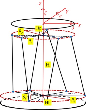
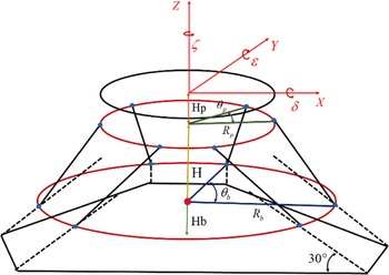
, that satisfies the constraints and maximizes the workspace volume while keeping the distances between the upper and lower hinge points (H), the center of the upper hinge distribution circle to the center of the upper platform top surface (Hp), and the center of the lower hinge distribution circle to the center of the lower platform bottom surface (Hb) constant, which is shown in Fig. 6. This ensures that the overall height of the PM remains constant. Specifically, these parameters are set at H = 0.2950 m, Hp = 0.0260 m, and Hb = 0.0270 m, respectively. The optimization is carried out for the 6-UCU manipulator in the fixed orientation position of δ = 0,
 $\varepsilon = 0$
, and ζ = 0, with the objective of maximizing the positional workspace volume. The optimization function and constraints are as follows:
The PM parameters.

 \begin{align} V^{\ast }=\max \{V_{6-UPU}(R_{b},R_{p},\theta _{b},\theta _{p})\} \nonumber \\ \begin{array}{l@{\quad}c} s.t.& l\in [l_{\min },l_{\max }]\\[3pt] & p\in [{-}0.05\text{m},0.05\text{m}]\\[3pt] & W_{u}\leq W_{\textit{joint}} \end{array} \end{align}
The equation
 $V_{6-UPU}(R_{b},R_{p},\theta _{b},\theta _{p})$
represents the calculation function of the positional workspace volume, with
 $l$
representing the four design parameters and
 $[l_{\min },l_{\max }]$
representing their domain value intervals, which range from
 $ 0.15\,\text{m}\leq R_{b}\leq 0.20\,\text{m}, 0.10\,\text{m}\leq R_{p}\leq 0.15\,\text{m}, 90^{\circ}\leq \theta _{b}\leq 100^{\circ} $
and
 $20^{\circ}\leq \theta _{p}\leq 30^{\circ}$
, respectively.
 $p$
represents the travel range of the driving pairs, while
 $W_{u}$
represents the workspace of the passive joints.
 $W_{\textit{joint}}$
represents the allowable workspace of the passive joints. The geometric parameters of the universal joints used in this model are shown in the third column of Table V. Based on this, an optimization model for the workspace volume of the 6-UCU PM is established. The structural parameters of the PM in the literature are selected as the initial values for the design, and the optimized results are shown in Table VI.
Initial parameter design and optimization results of 6-UCU PM with universal joints.

6-RR-RP-RR PM with offset joints.

4.1.2. Comparison of the PM workspace using various joint types
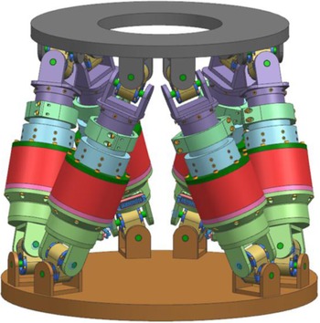
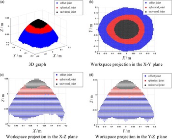
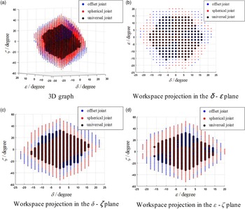
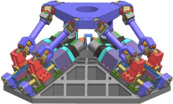
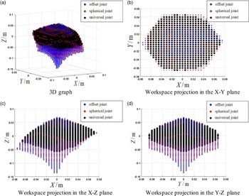
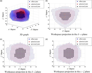
Because the offset-joint workspace is larger than that of the traditional universal joint and spherical joint, the workspace of Stewart PM with offset joints is larger than that of the traditional universal joint and spherical joint. Inverse kinematics solutions are used to solve the PM workspace with different joints to verify this assumption. The workspace is divided into position workspace and orientation workspace. The position workspace and orientation workspace of three types of PMs (6-RR-RP-RR PM using offset joints is shown in Fig. 7, 6-UCU PM using universal joints and 6-SPS PM using spherical joints) in the fixed initial position were analyzed, and the 3D graphics of the workspace are drawn in Figs. 8 and 9. The PM’s structural parameters were optimized and presented in Table VI, and the inverse kinematics of the 6-RR-RP-RR PM can be found in reference [Reference Zhang, Han, Xu, Han, Yu, Mao and Wu15]. The manipulator configuration parameters of the three PMs are identical, with only the joints being different. The parameters for the offset joints can be found in Table V, while the universal joint parameters are the same, but without offset. The spherical joints used are HEPHAIST SRJ012C-P, with a maximum allowable swing angle of 30°. Additionally, the leg elongation limitations of the PMs are the same, that is, 0.1 m.
Based on the images in Figs. 8 and 9, the PM position workspace with spherical joints is a subset of the PM position workspace with offset joints. Moreover, the PM position workspace with universal joints is much smaller than that of the PM with offset joints. The orientation PM workspace with the offset joints is similar to that of the PM with spherical joints, but it completely covers the PM with the universal joints. Because the offset joint has a wider rotation range than the spherical joint or the universal joint, the PM connecting the mobile platform and the fixed platform with the offset joints has a larger workspace than the spherical joints or the universal joints.
The numerical values of the workspace can be found in Table VII. The position workspace of the 6-RR-RP-RR PM with offset joints in the initial pose is 234.51% larger than that of the 6-UCU PM with universal joints and 66.45% larger than that of the 6-SPS PM with spherical joints. The orientation workspace in the initial pose is 209.79% larger than that of the 6-UCU PM and approximately the same as that of the 6-SPS PM, with an increase of 0.048%.
The numerical values of the workspace.

Positional workspace of PM with different joints in initial attitude.

Orientation workspace of PM with different joints in initial position.

4.2. 6-PURU PM
4.2.1. 6-PURU PM workspace optimization
Similar to the optimization of the workspace of the 6-UCU PM. The parameters are shown in Fig. 10, and the values of H, Hp, and Hb are kept constant at H = 0.1210 m, Hp = 0.0060 m, and Hb = 0.1256 m. The optimization is performed for the 6-PURU PM with fixed orientation position of δ = 0, ε = 0, and ζ = 0, with the aim of maximizing the positional workspace volume. The optimization function and constraints are as follows:
 \begin{align} V^{\ast }&=\max \!\left\{V_{6-PURU}\left(R_{b},R_{p},\theta _{b},\theta _{p}\right)\right\} \nonumber\\ &\begin{array}{l@{\quad}c} s.t. & l\in \left[l_{\min },l_{\max }\right]\\[3pt] & p\in \left[{-}0.05\text{m},0.05\text{m}\right]\\[3pt] & W_{u}\leq W_{\textit{joint}} \end{array} \end{align}
The equation
 $V_{6-PURU}(R_{b},R_{p},\theta _{b},\theta _{p})$
represents the calculation function of the positional workspace volume, with
 $l$
representing the four design parameters and
 $[l_{\min },l_{\max }]$
representing their domain value intervals, which range from
 $ 0.20\,\text{m}\leq R_{b}\leq 0.25\,\text{m}, 0.10\,\text{m}\leq R_{p}\leq 0.15\,\text{m}, 85^{\circ}\leq \theta _{b}\leq 95^{\circ} $
and
 $25^{\circ}\leq \theta _{p}\leq 35^{\circ}$
, respectively.
 $p$
represents the travel range of the driving pairs, while
 $W_{u}$
represents the workspace of the passive joints.
 $W_{\textit{joint}}$
represents the allowable workspace of the passive joints. The universal joint used in this model is the same as that of the 6-UCU PM. Based on this, an optimization model for the workspace volume of the 6-PURU PM is established. The structural parameters of the PM in the literature are selected as the initial values for the design and the optimized results are shown in Table VIII.
Initial parameter design and optimization results of 6-PURU PM with universal joints.

The PM parameters.

6-P-RR-R-RR PM with offset joints.

4.2.2. Comparison of the PM workspace using various joint types
The workspace comparison method is similar to that used in the previous section for the 6-UCU PM. Firstly, the inverse kinematics solution of the 6-P-RR-R-RR PM with offset joints needs to be obtained, which can be referenced in the literature [Reference Han, Zhang, Zhang, Han, Li and Xu12]. And the 3D model of the 6-P-RR-R-RR PM with offset joints can be found in Fig. 11. The positional and orientational workspace of three types of PMs, namely the 6-P-RR-R-RR PM using offset joints, the 6-PURU PM using universal joints, and the 6-PSS PM using spherical joints, were analyzed in the fixed initial position. The same offset, universal, and spherical joints as those used in the 6-UCU section were used in this analysis.
The conclusion of the workspace comparison is the same as the 6-RR-RP-RR section, as shown in Figs. 12 and13, which means that replacing the universal joint or spherical joint with offset joint can improve the workspace. The values of the workspace can be found in Table IX, where the position workspace of the 6-P-RR-R-RR PM with offset joints is improved by 30.36% compared to the 6-PURU PM with universal joints, and by 24.45% compared to the 6-PSS PM with spherical joints. At the initial pose, the orientation workspace of the 6-P-RR-R-RR PM is improved by 1024.42% compared to the 6-PURU PM and by 90.40% compared to the 6-PSS PM.
Positional workspace of PM with different joints in initial attitude.

The numerical values of the workspace.

Orientation workspace of PM with different joints in initial position.

5. Conclusion
In this study, the workspaces of a class of axial offset joints are investigated using theoretical parametric analysis and simulations. Given the interference of the joint caused by the contact between the upper and lower-joint brackets during the movement, a more accurate theoretical parametric model to describe the rotation range of axial offset joints is developed. The theoretical expressions of the offset-joint workspace are obtained via the coordinate system transformation method. The offset-joint workspace is first theoretically calculated in this study using the more accurate theoretical formulations. Based on the results, the primary observations are as follows:
-
1. The interference curve of the offset joint is formed by the contact of different parts of the upper- and lower-joint brackets of the joint, and the form of the joint’s workspace is determined by the interference curve of the joint.
-
2. The workspace of an axial offset joint can be expanded by increasing its offset value. For an axial offset joint with fixed geometrical parameter’s joint brackets, an axial offset joint has the larger the offset amount, the wider the motion range, and the larger the workspace. Theoretical expressions can be utilized by researchers during the design of such joints to accurately predict their workspace.
-
3. The workspace of the 6-RR-RP-RR PM with offset joints significantly outperforms the PM of the same configuration with universal joints and spherical joints.
The findings of this study are helpful for the design of axial offset joints achieving a PM design with a large workspace and carrying capacity.
Author contributions
Peiyi Li and Hasiaoqier Han conceived and designed the study. Peiyi Li and Hasiaoqier Han conducted data gathering. Peiyi Li, Hasiaoqier Han, Chunlong Liu, and Biao Ren wrote the paper. Hasiaoqier Han, Qingwen Wu, and Zhenbang Xu guided the progress and reviewed the paper.
Financial support
This work was supported by the National Natural Science Foundation of China (Grant No. 52005478) and the Youth Innovation Promotion Association, Chinese Academy of Sciences (Grant No. 2022215).
Competing interests
No competing financial interests exist.
Ethical approval
Not applicable.
Appendix A.
The limitation of the offset joint
 $\gamma _{\max }\gt 90^{\circ}$
To ensure that the maximum rotation angle of the joint is greater than 90 degrees, as shown in Fig. A.1(a), it is necessary to satisfy
 $B_{1}F_{1}\gt B_{1}E_{1}$
. In the triangle
 $B_{1}C_{1}E_{1}, C_{1}E_{1}=a_{1}$
and
 $B_{1}C_{1}=A_{1}C_{1}-A_{1}B_{1}=b-e, \angle B_{1}C_{1}E_{1}=90^{\circ}$
, therefore
 $B_{1}{E_{1}}^{2}=C_{1}{E_{1}}^{2}+B_{1}{C_{1}}^{2}=(b-e)^{2}+{a_{1}}^{2}$
, and
 $B_{1}F_{1}=h_{2}$
. Hence,
 $a_{1}^{2}+(b-e)^{2}\lt {h_{2}}^{2}$
.
The limitation of the offset joint
 $\gamma _{\max }\gt 90^{\circ}$
.

In Fig. A.1(b), to ensure that there is no interference between the upper- and lower-joint brackets of the offset joint, it is necessary to have
 $J_{1}K_{1}\gt M_{1}N_{1}$
. Hence,
 $b\lt a_{2}$
.
Clearly,
 $h_{2}\lt h_{1}, a_{2}\lt a_{1}$
. Hence,
 $a_{1}^{2}+(b-e)^{2}\lt {h_{2}}^{2}\lt {h_{1}}^{2}, b\lt a_{2}\lt a_{1}$
.
The limitation of the offset joint
 $\gamma _{\max }\lt 90^{\circ}$
To ensure that the maximum rotation angle of the joint is less than 90 degrees, as shown in Fig. A.2(a), it is necessary to satisfy
 $ B_{2}E_{2}\gt B_{2}F_{2}\gt B_{2}G_{2}$
. In triangle
 $B_{2}C_{2}E_{2}, C_{2}E_{2}=a_{1}$
, and
 $B_{2}C_{2}=A_{2}C_{2}-A_{2}B_{2}=b-e, \angle B_{2}C_{2}E_{2}=90^{\circ}$
, therefore
 $B_{2}{E_{2}}^{2}=C_{2}{E_{2}}^{2}+B_{2}{C_{2}}^{2}={a_{1}}^{2}+(b-e)^{2}$
. And
 $B_{2}F_{2}=h_{2}$
. Therefore,
 $a_{1}^{2}+(b-e)^{2}\gt {h_{2}}^{2}$
. In triangle
 $B_{2}C_{2}G_{2}, C_{2}G_{2}=a_{2}, \angle B_{2}C_{2}G_{2}=90^{\circ}$
, so
 $B_{2}{G_{2}}^{2}=C_{2}{G_{2}}^{2}+B_{2}{C_{2}}^{2}={a_{2}}^{2}+(b-e)^{2}$
. Therefore,
 ${h_{2}}^{2}\gt a_{2}^{2}+(b-e)^{2}$
.
The limitation of the offset joint
 $\gamma _{\max }\lt 90^{\circ}$
.

In Fig. A.2(b), to ensure that there is no interference between the upper and lower joint brackets of the offset joint, it is necessary to have
 $J_{2}K_{2}\gt M_{2}N_{2}$
. Hence,
 $b\lt a_{2}$
.
Clearly,
 $h_{2}\lt h_{1}, a_{2}\lt a_{1}$
. Hence,
 $a_{1}^{2}+(b-e)^{2}\gt h_{2}^{2}\gt a_{2}^{2}+e^{2}-2be, b\lt a_{2}\lt a_{1}$
.
Appendix B.
Derivation of
 ${\gamma}_{1}$
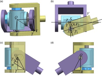
When the joint attitude is at the position depicted in Fig. B.1, the lower-joint bracket rotates at an angle of
 $\gamma _{1}$
relative to the offset joint.
Schematic of characteristic pose for deriving
 $\gamma _{1}$
.

 $\gamma _{1}$
can be represented as follows:
 \begin{equation} \gamma _{1}=\frac{\pi }{2}+\angle VQU-\angle VQW \end{equation}
In triangle WQV,
 $QW=h_{2}, VW=b, QW\bot VW$
. Hence,
 $QV=\sqrt{QW^{2}+VW^{2}}=\sqrt{h_{2}^{2}+b^{2}}, \angle VQW=\arccos \!\left(\frac{QW}{QV}\right)=\arccos \!\left(\frac{h_{2}}{\sqrt{h_{2}^{2}+b^{2}}}\right)$
.
In triangle UQV,
 $QU=a_{1}, QU\bot UV$
. Hence,
 $\angle VQU=\arccos \!\left(\frac{QU}{QV}\right)=\arccos \!\left(\frac{a_{1}}{\sqrt{h_{2}^{2}+b^{2}}}\right)$
.
 $\gamma _{1}$
can be solved as follows:
 \begin{equation} \gamma _{1}=\frac{\pi }{2}+\arccos \!\left(\frac{a_{1}}{\sqrt{b^{2}+h_{2}^{2}}}\right)-\arccos \!\left(\frac{h_{2}}{\sqrt{b^{2}+h_{2}^{2}}}\right) \end{equation}
Derivation of
 ${\gamma}_{{2}}$
When the joint attitude is at the position depicted in Fig. B.2, the lower-joint bracket rotates at an angle of
 $\gamma _{2}$
relative to the offset joint.
 $\gamma _{2}$
can be represented as follows:
 \begin{equation} \gamma _{2}=\angle WUV-\angle TUV \end{equation}
Schematic of characteristic pose for deriving
 $\gamma _{2}$
.

In triangle RYX,
 $RX=e, \angle YXR=\gamma _{1}-90^{\circ},\ RY=RX\sin (\angle YXR)=e\sin (\gamma _{1}-90^{\circ})=-e\cos (\gamma _{1}), XY=RX\cos (\angle YXR)=e\cos (\gamma _{1}-90^{\circ})=e\sin (\gamma _{1})$
.
In rectangle ZSRY,
 $RY=SZ$
,
hence,
 $SV=ZV-ZS=h_{2}+e\cos (\gamma _{1}), RS=YZ=XZ-XY=b-e\sin (\gamma _{1})$
.
In triangle QRS,
 $QR\bot RS, RS=b-e\sin (\gamma _{1}), QR=a_{2}$
,
hence,
 $QS=\sqrt{QR^{2}+RS^{2}}=\sqrt{a_{2}^{2}+(b-e\sin (\gamma _{1}))^{2}}$
.
In triangle QSV,
 $QS\bot SV, SV=h_{2}+e\cos (\gamma _{1})$
,
hence,
 $QV=\sqrt{QS^{2}+SV^{2}}=\sqrt{a_{2}^{2}+(b-e\sin (\gamma _{1}))^{2}+(h_{2}+e\cos (\gamma _{1}))^{2}}$
.
In triangle QUV,
 $QU\bot UV$
. Hence,
 $QU=a_{1}, UV=\sqrt{QV^{2}-QU^{2}}=\sqrt{a_{2}^{2}+(b-e\sin (\gamma _{1}))^{2}+(h_{2}+e\cos (\gamma _{1}))^{2}-a_{1}^{2}}$
.
In triangle UWV,
 $UW\bot WV, UW=b$
. Hence,
 $\angle WUV$
can be calculated as follows:
 \begin{equation} \angle WUV=\arccos \frac{UW}{UV}=\arccos \frac{b}{\sqrt{a_{2}^{2}+\left(b-e\sin \!\left(\gamma _{1}\right)\right)^{2}+\left(h_{2}+e\cos \!\left(\gamma _{1}\right)\right)^{2}-a_{1}^{2}}} \end{equation}
In triangle TUV,
 $UT\bot TV, UT=a_{2}$
. Hence,
 $\angle TUV$
can be calculated as follows:
 \begin{equation} \angle TUV=\arccos \frac{UT}{UV}=\arccos \frac{a_{2}}{\sqrt{a_{2}^{2}+\left(b-e\sin \!\left(\gamma _{1}\right)\right)^{2}+\left(h_{2}+e\cos \!\left(\gamma _{1}\right)\right)^{2}-a_{1}^{2}}} \end{equation}
 $\gamma _{2}$
can be solved as follows:
 \begin{align} \gamma _{2} & =\arccos \frac{b}{\sqrt{a_{2}^{2}+\left(b-e\sin \!\left(\gamma _{1}\right)\right)^{2}+\left(h_{2}+e\cos \!\left(\gamma _{1}\right)\right)^{2}-a_{1}^{2}}} \nonumber \\ &\quad -\arccos \frac{a_{2}}{\sqrt{a_{2}^{2}+\left(b-e\sin \!\left(\gamma _{1}\right)\right)^{2}+\left(h_{2}+e\cos \!\left(\gamma _{1}\right)\right)^{2}-a_{1}^{2}}} \end{align}
Derivation of
 ${\gamma}_{3}$
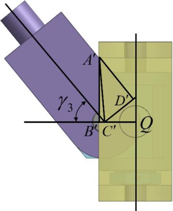
When the joint attitude is at the position depicted in Fig. B.3, the lower-joint bracket rotates at an angle of
 $\gamma _{3}$
relative to the offset joint.
Schematic of characteristic pose for deriving
 $\gamma _{3}$
.

In quadrangle
 $A^{\prime}B^{\prime}C^{\prime}D^{\prime}, \gamma _{3}$
can be represented as follows:
 \begin{equation*} \gamma _{3}=\frac{\pi }{2}-\angle B^{\prime}A^{\prime}C^{\prime}-\angle C^{\prime}A^{\prime}D^{\prime} \end{equation*}
In triangle
 $A^{\prime}B^{\prime}C^{\prime}, A^{\prime}B^{\prime}\bot B^{\prime}C^{\prime}, A^{\prime}B^{\prime}=a_{2}, B^{\prime}C^{\prime}=b-e$
. Hence,
 $A^{\prime}C^{\prime}=\sqrt{A^{\prime}B^{\prime 2}+B^{\prime}C^{\prime 2}}=\sqrt{a_{2}^{2}+\left(b-e\right)^{2}}, \angle B^{\prime}A^{\prime}C^{\prime}=\arctan \frac{B^{\prime}C^{\prime}}{A^{\prime}B^{\prime}}=\arctan \!\left(\frac{b-e}{a_{2}}\right)$
.
In triangle
 $A^{\prime}D^{\prime}C^{\prime}, A^{\prime}D^{\prime}\bot C^{\prime}D^{\prime}, C^{\prime}D^{\prime}=b$
. Hence,
 $A^{\prime}D^{\prime}=\sqrt{A^{\prime}C^{\prime 2}-C^{\prime}D^{\prime 2}}=\sqrt{a_{2}^{2}+\left(b-e\right)^{2}-b^{2}},$
 $\angle C^{\prime}A^{\prime}D^{\prime}=\arctan \frac{C^{\prime}D^{\prime}}{A^{\prime}D^{\prime}}=\arctan \!\left(\frac{b}{\sqrt{a_{2}^{2}+\left(b-e\right)^{2}-b^{2}}}\right)$
.
 $\gamma _{3}$
can be solved as follows:
 \begin{equation} \gamma _{3}=\frac{\pi }{2}-\arctan \!\left(\frac{b-e}{a_{2}}\right)-\arctan \!\left(\frac{b}{\sqrt{a_{2}^{2}+\left(b-e\right)^{2}-b^{2}}}\right) \end{equation}
Appendix C.
Segment I
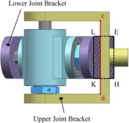
First, the offset joint moves from Pose I to Pose II; the interference curve is formed by the contact between the upper-joint bracket edge cd and lower-joint bracket side plane LKHE. The kinematics equation can be expressed as follows:
 \begin{equation} \beta =\gamma _{1}, 0\leq \alpha \lt \gamma _{2} \end{equation}
Eq. (C.1) can express the relationship between two independent rotation angle variables α and β under the first-stage interference motion.
Segment II
Second, the offset joint moves from Pose II to Pose III; the offset joint’s upper-joint bracket edge jd makes contact with the lower-joint bracket edge KH to form an interference curve.
The upper-joint bracket edge jd can be expressed in coordinate system
 $O^{\prime}_{2}-x^{\prime}_{2}y^{\prime}_{2}z^{\prime}_{2}$
as follows:
 \begin{equation} {}^{O^{\prime}2}{\boldsymbol{{j}}}{}\boldsymbol{{d}}=\left[\begin{array}{l@{\quad}l@{\quad}l} b & -a_{2} & t_{1} \end{array}\right]^{\text{T}}, t_{1}\in (0,h_{2}) \end{equation}
The lower-joint bracket edge KH can be expressed in coordinate system
 $O_{1}-x_{1}y_{1}z_{1}$
as follows:
 \begin{equation} {}^{O_1}{\boldsymbol{{K}}}{}\boldsymbol{{H}}=\left[\begin{array}{l@{\quad}l@{\quad}l} a_{1} & -b & t_{3} \end{array}\right]^{\text{T}}, t_{3}\in (0,-h_{1}) \end{equation}
The expression of the upper-joint bracket edge jd in coordinate system
 $O_{1}-x_{1}y_{1}z_{1}$
can be obtained by coordinate transformation, and it can be expressed as follows:
 \begin{equation} \begin{array}{l@{\quad}l} {}^{O_1}{\boldsymbol{{j}}}{}\boldsymbol{{d}} & =\boldsymbol{{R}}_{x}(\boldsymbol{{R}}_{y}{}^{O^{\prime}2}{\boldsymbol{{j}}}{}\boldsymbol{{d}}+\boldsymbol{{p}})\\[3pt] & =\left[\begin{array}{c} b\cos \beta +t_{1}\sin \beta \\[3pt] \mathit{b}\sin \alpha \sin \beta -a_{2}\cos \alpha -t_{1}\sin \alpha \cos \beta -e\sin \alpha \\[3pt] -\mathit{b}\cos \alpha \sin \beta -a_{2}\sin \alpha +t_{1}\cos \alpha \cos \beta +e\cos \alpha \end{array}\right] \end{array} \end{equation}
where
 $\boldsymbol{{R}}_{x}=\left[\begin{array}{c@{\quad}c@{\quad}c} 1 & 0 & 0\\[3pt] 0 & \cos \alpha & -\sin \alpha \\[3pt] 0 & \sin \alpha & \cos \alpha \end{array}\right]$
,
 $\boldsymbol{{R}}_{y}=\left[\begin{array}{c@{\quad}c@{\quad}c} \cos \beta & 0 & \sin \beta \\[3pt] 0 & 1 & 0\\[3pt] -\sin \beta & 0 & \cos \beta \end{array}\right], \boldsymbol{{p}}=\left[\begin{array}{l} 0\\ 0\\ e \end{array}\right]$
.
 $\boldsymbol{{R}}_{x}$
is the rotation matrix of rotation α degree about the X-axis.
 $\boldsymbol{{R}}_{y}$
is the rotation matrix of rotation β degree about the Y-axis. Moreover,
 $\boldsymbol{{p}}$
is the translation matrix of e along the Z-axis.
Because the upper-joint bracket edge jd of the offset joint is in contact with the lower-joint bracket edge KH of the offset joint, the equation has the same solution as follows:
 \begin{equation} {}^{O_1}{\boldsymbol{{K}}}{}\boldsymbol{{H}}\boldsymbol{{=}}{}^{O_1}{\boldsymbol{{j}}}{}\boldsymbol{{d}} \end{equation}
 \begin{equation} \left\{\begin{array}{l} a_{1}=b\cos \beta +t_{1}\sin \beta \\[3pt] -b=\mathit{b}\sin \alpha \sin \beta -a_{2}\cos \alpha -t_{1}\sin \alpha \cos \beta -e\sin \alpha \\[3pt] t_{3}=-\mathit{b}\cos \alpha \sin \beta -a_{2}\sin \alpha +t_{1}\cos \alpha \cos \beta +e\cos \alpha \end{array}\right. \end{equation}
Combine the first two equations of Eq. (C.6) and eliminate the variable
 $t_{1}$
:
 \begin{equation} b\tan \beta +b\frac{\sin \alpha }{\cos \beta }-a_{2}\cos \alpha \tan \beta -a_{1}\sin \alpha -\mathit{e}\sin \alpha \tan \beta =0 \end{equation}
For simple calculation, define
 $x_{2}=\tan \beta$
:
 \begin{equation} \begin{array}{l} [(a_{2}\cos \alpha -b+e\sin \alpha )^{2}-b^{2}\sin ^{2}\alpha ]{x_{2}}^{2}+2a_{1}\sin \alpha (a_{2}\cos \alpha -b+e\sin \alpha )x_{2}\\ +(a_{1}^{2}-b^{2})\sin ^{2}\alpha =0 \end{array} \end{equation}
Eq. (C.8) is a quadratic polynomial. In this second-stage motion,
 $90^{\circ}\lt \beta \lt 180^{\circ}$
and
 $\tan \beta \lt 0$
. Therefore, the equation can be solved as follows:
 \begin{align} x_{2}&=\frac{a_{1}\sin \alpha \!\left(a_{2}\cos \alpha -b+e\sin \!\left(\alpha \right)\right)+b\sin \alpha \sqrt{\left(a_{2}\cos \alpha -b+e\sin \!\left(\alpha \right)\right)^{2}-b^{2}\sin ^{2}\alpha +{a_{1}}^{2}\sin ^{2}\alpha }}{b^{2}\sin ^{2}\alpha -\left(a_{2}\cos \alpha -b+e\sin \!\left(\alpha \right)\right)^{2}} \nonumber \\ \beta &=\pi +\arctan \!\left(x_{2}\right), \gamma _{2}\leq \alpha \lt \gamma _{3} \end{align}
Eq. (C.9) can express the relationship between two independent rotation angle variables α and β under the second-stage interference motion.
Segment III
Third, the offset joint moves from Pose III to Pose IV, in which the interference curve is formed by the contact between the upper-joint bracket edge jd and lower-joint bracket edge JD to form an interference curve.
The lower-joint bracket edge JD can be expressed in coordinate system
 $O_{1}-x_{1}y_{1}z_{1}$
as follows:
 \begin{equation} {}^{O_1}{\boldsymbol{{J}}}{}\boldsymbol{{D}}=[\begin{array}{l@{\quad}l@{\quad}l} a_{2} & -b & t_{3} \end{array}]^{\text{T}}, t_{3}\in (0,-h_{2}) \end{equation}
like the derivation of the interference motion curve in the second segment:
 \begin{equation} {}^{O_1}{\boldsymbol{{J}}}{}\boldsymbol{{D}}\boldsymbol{{=}}{}^{O_1}{\boldsymbol{{j}}}{}\boldsymbol{{d}} \end{equation}
 \begin{equation} b\tan \beta +b\frac{\sin \alpha }{\cos \beta }-a_{2}\cos \alpha \tan \beta -a_{2}\sin \alpha -\mathit{e}\sin \alpha \tan \beta =0 \end{equation}
Similarly, define
 $x_{3}=\tan \beta$
:
 \begin{align} & \left[(a_{2}\cos \alpha -b+e\sin \alpha )^{2}-b^{2}\sin ^{2}\alpha \right]{x_{3}}^{2}+2a_{2}\sin \alpha (a_{2}\cos \alpha -b+e\sin \alpha )x_{3} \nonumber \\ & \quad +(a_{2}^{2}-b^{2})\sin ^{2}\alpha =0 \end{align}
In this third-stage motion,
 $0^{\circ}\lt \beta \lt 90^{\circ}$
and
 $\tan \beta \gt 0$
. Therefore, the equation can be solved as follows:
 \begin{align} x_{3}&=\frac{a_{2}\sin \alpha \!\left(a_{2}\cos \alpha -b+e\sin \!\left(\alpha \right)\right)+b\sin \alpha \sqrt{\left(a_{2}\cos \alpha -b+e\sin \!\left(\alpha \right)\right)^{2}-b^{2}\sin ^{2}\alpha +{a_{2}}^{2}\sin ^{2}\alpha }}{b^{2}\sin ^{2}\alpha -\left(a_{2}\cos \alpha -b+e\sin \!\left(\alpha \right)\right)^{2}} \nonumber \\ \beta &=\arctan (x_{3}), \gamma _{3}\leq \alpha \lt \pi /2 \end{align}
Eq. (C.14) can express the relationship between two independent rotation angle variables α and β under the third-stage interference motion.
Segment IV
Fourth, the offset joint moves from Pose IV to Pose V, in which the offset joint’s upper-joint bracket edge hk makes contact with the lower-joint bracket edge JD to form an interference curve.
The upper-joint bracket edge hk can be expressed in coordinate system
 $O^{\prime}_{2}-x^{\prime}_{2}y^{\prime}_{2}z^{\prime}_{2}$
as follows:
 \begin{equation} {}^{O^{\prime}2}{\boldsymbol{{h}}}{}\boldsymbol{{k}}=[\begin{array}{l@{\quad}l@{\quad}l} b & -a_{1} & t_{1} \end{array}]^{\text{T}}, t_{1}\in (0,h_{1}) \end{equation}
Similarly, the equation of the interference curve can be deduced as follows:
 \begin{equation} {}^{O_1}{\boldsymbol{{J}}}{}\boldsymbol{{D}}\boldsymbol{{=}}{}^{O_1}{\boldsymbol{{h}}}{}\boldsymbol{{k}}\boldsymbol{{=}}\boldsymbol{{R}}_{x}(\boldsymbol{{R}}_{y}\cdot {}^{O^{\prime}2}{\boldsymbol{{h}}}{}\boldsymbol{{k}}+\boldsymbol{{p}}) \end{equation}
 \begin{equation} b\tan \beta +b\frac{\sin \alpha }{\cos \beta }-a_{2}\cos \alpha \tan \beta -a_{1}\sin \alpha -\mathit{e}\sin \alpha \tan \beta =0 \end{equation}
Likewise, define
 $x_{4}=\tan \beta$
:
 \begin{align} & \left[(a_{1}\cos \alpha -b+e\sin \alpha )^{2}-b^{2}\sin ^{2}\alpha \right]{x_{4}}^{2}+2a_{2}\sin \alpha (a_{1}\cos \alpha -b+e\sin \alpha )x_{4} \nonumber \\ & \quad +(a_{2}^{2}-b^{2})\sin ^{2}\alpha =0 \end{align}
Because in this fourth-stage motion,
 $0^{\circ}\lt \beta \lt 90^{\circ}, \tan \beta \gt 0$
. Therefore, Eq. (C.18) can be solved as follows:
 \begin{align} x_{4} & =\frac{a_{2}\sin \alpha \!\left(a_{1}\cos \alpha -b+e\sin \!\left(\alpha \right)\right)+b\sin \alpha \sqrt{\left(a_{1}\cos \alpha -b+e\sin \!\left(\alpha \right)\right)^{2}-b^{2}\sin ^{2}\alpha +{a_{2}}^{2}\sin ^{2}\alpha }}{b^{2}\sin ^{2}\alpha -\left(a_{1}\cos \alpha -b+e\sin \!\left(\alpha \right)\right)^{2}} \nonumber \\ \beta &=\arctan (x_{4}), \pi /2\leq \alpha \lt \gamma _{1} \end{align}
Eq. (C.19) can express the relationship between two independent rotation angle variables α and β under the fourth-stage interference motion.
Segment V
Fifth, the offset joint moves from Pose V to Pose VI, in which the interference curve is formed by the contact between the upper-joint bracket side plane lkhe and lower-joint bracket edge CD. The kinematics equation can be expressed as follows:
 \begin{equation} \alpha =\gamma _{1}, 0\leq \beta \leq \gamma _{2} \end{equation}
Eq. (C.20) can express the relationship between two independent rotation angle variables α and β under the fifth-stage interference motion.