Introduction
The increasing demand for communication systems with high spectral performance and high data rates is driving the growth of improved communication devices. Ultra-wideband (UWB) communication and the UWB planar antennas can provide short-range communication using the 3.1–10.6 GHz allocated spectrum; however, wireless personal area network consumers have personal interest in super wideband (SWB) transceivers that cover both short- and long-range communication with wider bandwidth (BW), high data rate, increased coverage, and maximum resolution. An SWB antenna can be customized for the purpose and should ideally be designed for a BW ratio of at least 10:1 for return loss of ≤ 10 dB and, based on the propagation demands, be either omnidirectional or directional. In the literature, numerous SWB antennas have been reported.
In [Reference Liang, Zhong and Wang1], a coplanar waveguide (CPW)-fed planar elliptical antenna for SWB applications showed a BW ratio of 21.6:1 and in [Reference Yan, Zhong and Liang2] using a semi-elliptical patch radiator a BW ratio of 19.7:1 is obtained. These designs, however, partially covered the entire UWB frequency spectrum. In [Reference Liu, Zhong and Esselle3], the same authors further improved the BW achieved in [Reference Liang, Zhong and Wang1] by introducing a semicircular-shaped branch connected to the tapered feed line of the patch antenna; this led to an impedance BW from 1.02 to 24.1 GHz. A similar design presented in [Reference Liu, Esselle, Hay and Zhong4] achieved an impedance BW from 1.08 to 27.4 GHz and a compact version of the same design [Reference Rafique, Ahmed, Hassan and Khalil5] improved the lower frequency range and BW dimension ratio (BDR) performance. In contrast, to achieve wider impedance BW, a tailored patch radiator was used in [Reference Dong, Hong, Liu, Zhang and Kuai6] with a tapered feed line. A similar technique was used in [Reference Liu, Esselle, Hay and Zhong7] to further enhance the BW ratio to 34:1. SWB performance reported an impedance BW from 0.65 to 35.61 GHz and a BW ratio of 54.78:1. Although the designs from [Reference Liu, Esselle, Hay and Zhong4–Reference Rafique and Din9] provided high impedance BW, BW ratio, and BDR, their relatively large sizes (smallest footprint 80 × 80 mm2 [Reference Rafique and Din9]) are no opportunistic for small equipment integration.
An egg-shaped planar monopole antenna with dimensions 35 × 77 mm2 is reported [Reference Chen and Row10] for SWB applications. It uses a semi-elliptical fractal-complementary slot into an asymmetrical ground to achieve an impedance BW of 172%, that is, from 1.44 to 18.8 GHz. In [Reference Gorai, Karmakar, Pal and Ghatak11], a CPW-fed propeller-shaped SWB planar antenna of size 38 × 55 mm2 is reported. This design offers a super-wide impedance BW from 3 to 35 GHz and a BW ratio of 11.6:1; however, its attained BDR was 805 which is relatively low. In [Reference Samsuzzaman and Islam12], a semi-circular-shaped monopole antenna with a trapezoidal ground plane was investigated where a tapered feed line was used to excite the semi-circle patch. This design of size 52 × 42 mm2 provides a BDR of 4261 for an impedance BW from 1.3–20 GHz and BW ratio of 15.38:1. A smaller profile antenna of size 30 × 40 mm2 was designed in [Reference Tang, Ziolkowski and Xiao13] based on a parasitic oval patch built in an elliptical slot and a microstrip-line-fed elliptical tuning fork element. This led to an antenna with an impedance BW of 19.92 GHz measured from 2.26 to 22.18 GHz. In [Reference Hakimi, Rahim, Abedian, Noghabaei and Khalily14], a CPW-fed transparent antenna of size 45 × 30 mm2 was presented for enhanced impedance BW. A staircase rectangular radiator was used to generate overlapped resonant frequencies and complemented with two major and minor symmetrical rectangular stubs in the ground plane to increase BW. This led to an impedance BW of 28.85 GHz measured from 3.15 to 32 GHz, however, its BDR of 1127 is still relatively low, though the BW ratio is 10.16:1. The immediately outlined literature review reveals that enhancing the impedance BW of an antenna either compromises its overall size or its BDR performance. Therefore, a compact antenna having an SWB characteristic with high BDR is challenging here.
As stated earlier, because of the rich spectrum resource, high transmission rate, strict secrecy, and low power consumption requirements, SWB systems have received a lot of attention. To improve multipath fading capability, multiple input-multiple output (MIMO) antenna configurations are attractive. With this, the propagation distance can be enhanced for a given input power. The use of MIMO antenna configurations for SWB applications with high isolation among the multiple antenna elements is challenging. In [Reference Mao and Chu15] a split-ring resonator arrangement was used to achieve a band-notch, and a T-shaped slot was made in the ground plane to improve isolation between antennas, which was below − 15 dB in the operating band. A rectangular slot and T-shaped stub in the ground plane were made for a dual-polarized UWB-MIMO antenna [Reference Mao and Chu15], lowering the coupling between antennas to less than − 20 dB. Using polarization diversity, a four-element UWB-MIMO antenna has been presented in [Reference Khan, Capobianco, Asif, Iftikhar, Ijaz and Braaten16]. An integrated four-element UWB-MIMO antenna based on frequency reconfiguration was fabricated for cognitive radio applications in [Reference Hussain, Khan and Sharawi17].
In this paper, a compact SWB annular ring antenna using 45° clock-wise square patch inclusions for super high frequency (SHF) and polarization diversity applications is proposed. The inclusions consist of square patches with inscribed etched circles and is fed using a 50 Ω microstrip line. The antenna offers a fractional bandwidth (FBW) of 174.2% over the operating frequency (f 0) of 2.97–30 GHz and is suitable for SHF applications including Wi-Fi/WLAN, WiMAX, radar communication, satellite and defense communication, and mm-wave communication. For the polarization diversity a 4 × 4 MIMO configuration is devised and manufactured, offering an effective isolation of ≥ 22.5 dB between ports and corroborated by measurements. Following the proposed antenna introduction, its design and evolution is given in Section “Proposed antenna design and evolution,” its fabrication and validation in Section “Fabrication and validation,” a time-domain analysis using the proposed antenna as a transmitter (Tx) and as a receiver (Rx) in Section “Time-domain analysis,” a MIMO configuration in Section “MIMO configuration,” and concluding remarks are provided in the final section.
Proposed antenna design and evolution
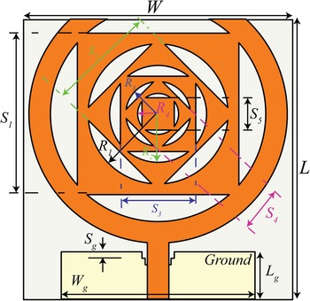
The geometry of the proposed compact SWB annular ring antenna using 45° clock-wise square patch inclusions for SHF applications is shown in Fig. 1.
Geometry of the proposed SWB antenna.

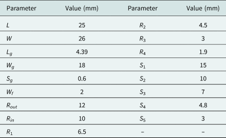
The inclusions consist of square patches (S 1−5) with inscribed etched circles (R 1−4) and form the radiating elements of the antenna. The design is symmetrical along the vertical axis and it will be shown attractive to allow the current distribution to remain symmetric throughout the design evolution. It uses a partial ground plane with a 4-stair-type defect at the back of the substrate (Fig. 1) for good impedance matching over the BW and etched on a commercially available FR-4 substrate having dielectric constant ɛr = 4.4, substrate height h = 1.6 mm, and loss tangent tan δ = 0.02. A 50 Ω microstrip line fed the antenna whose dimensions were calculated using standard equations [Reference Balanis18] and iteratively optimized for optimum performance. CST Microwave Studio was used for the design and led to a compact prototype W, ~ L (Fig. 1) of 25 × 26 mm2 (0.17λ × 0.18λ).
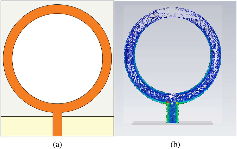
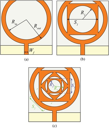
Initially, a conventional annular ring antenna, Fig. 2(a), was designed using standard equations [Reference Kumar and Ray19] and conveniently simulated. Observations on the surface maximum current distribution, shown in Fig. 2(b), suggested the removal of the area in which the currents are low. Most of the currents were concentrated toward the feed line with minimal concentrations opposite to the feed. This area of minimal concentrations was removed and resulted in a relatively smaller design; this is presented in Fig. 3(a) and termed as evolved 0 design.
(a) Conventional annular ring antenna and (b) surface current distribution.

Evolution of the proposed antenna: (a) evolved 0 design, (b) evolved 1 design, and (c) evolved 2 design.

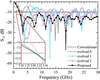
The simulated reflection coefficient (S 11) of the conventional annular ring antenna and evolved 0 to 2 are shown in Fig. 4. Results show evolved 0 design with f 0 of 2.1–4.5, 10.95–12, 13.83–16, 17–20.45, 22.2–27.25, and 28.4–30 GHz measured at −10 dB and leading to a multi-band antenna.
Simulated S 11 parameters of evolved antennas.

Next, to achieve a SWB response by maintaining same physical size, a square patch of side S 1 having a circular slot of radius R 1 was included in the inner area of the annular ring of evolved 0 design; the resulting design is shown in Fig. 3(b) referred to it as evolved 1. Adding these structures help in increasing the electrical length of the antenna by providing multiple paths for the current to pass. As a result, the evolved 1 design resonated in the 2.05–6.28, 9.1–14.80, 15.65–20.90, 22.90–28.42, and 29.32–30 GHz frequency bands (measured at −10 dB).
Additional inclusions were performed to further increase the BW performance to form the final evolved design. This was made by two more clock-wise 45° rotated square patches of sides S 2 and S 3 having circular slots of radii R 2 and R 3 respectively, Fig. 3(c). This led to the evolved 2 design with satisfactory performance over the intended frequency range. However, impedance mismatch was observed (Fig. 4) at 8.5, 11.8, 14.5, and 20.7–22.7 GHz measured at −10 dB.
Finally, referred as proposed design (Fig. 1), two additional square patches of side S 4 and S 5 were included in the previous evolved 2 design out of which the fourth square (S 4) is having a circular slot of radius R 4. This resulted in an impedance matching away from the initially intended 50 Ω specially at the high frequency (f h) of operation and to accommodate this, a stair-type defect was made in the ground plane. This led to a proposed compact SWB annular ring antenna design using 45° clock-wise square patch inclusions for SHF applications with a f 0 between 2.07 and 30 GHz (measured at −10 dB). From the inset of Fig. 4, it can also be seen that, the lower cut-off frequency shifts mainly for the first inclusion and not others. Since the lowest cut-off frequency is caused by the outermost structures, it does not change much for inner inscribed shapes. On the contrary, the inner shapes improve the response at higher frequencies by generating multiple constructive resonances. This is further validated by Fig. 9.
The final dimensions of the proposed antenna are listed in Table 1.
Dimensions of the proposed antenna

Fabrication and validation
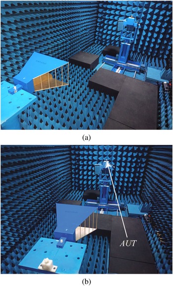
The proposed antenna was fabricated and measured. A Power Network Analyzer (PNA-L) N5234B by Agilent Technologies was used for the experiments. Anechoic chamber setup for antenna measurement is shown in Fig. 5.
Measurement setup inside an anechoic chamber.

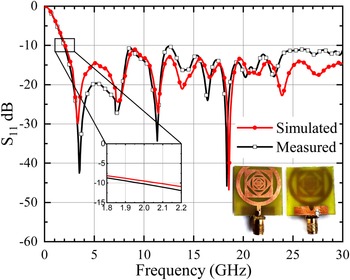
The fabricated prototype and S 11 parameters of the fabricated antenna (compared to simulated) are shown in Fig. 6.
S 11 parameters of the proposed antenna with the fabricated prototype.

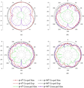
Experimental results show a compact SWB annular ring antenna using 45° clock-wise square patch inclusions for SHF applications having a BW of 28 GHz over the f 0 of 2–30 GHz. Measured and simulated results are in fair agreement as shown in Fig. 6. The simulated (co- and cross-polar) and measured (co-polar) radiation patterns of the antenna are shown in Fig. 7. Only relevant patterns measured at 5, 13, 21, and 28 GHz are shown. The patterns are all pretty much omnidirectional for the H-plane (ϕ = 90°) and dipole-like for the E-plane (ϕ = 0°); this is more apparent at 5 GHz, Fig. 7(a). At higher frequencies 13, 21, and 28 GHz, Figs 7(b)–7(d), the E-plane is not that dipole-like also H-plane is not omnidirectional due to the excitation of higher order modes [Reference Rafique and Din9], however, these modes did not present a negative influence in real applications. Also, the level of cross-polarized patterns is approaching toward co-polar patterns for some angles. This also occurs due to excitation of higher order modes at higher frequencies. Measured and simulated results are in fair agreement, validating the fabricated antenna.
Simulated and measured radiation patterns of the proposed antenna at (a) 5 GHz, (b) 13 GHz, (c) 21 GHz, and (d) 28 GHz.

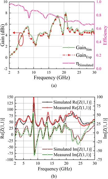
The gain was measured and corroborated with simulations as shown in Fig. 8(a). Peak gains of 8 dBi are recorded for the simulated and measured results with strong agreement between both the results. The gain pattern is in accordance with [Reference Hakimi, Rahim, Abedian, Noghabaei and Khalily14, Reference Rahman, Cao, Ullah and Khalil20–Reference Yeo and Lee23]. Figure 8(b) shows the input impedance of the antenna. Although it is normal to vary over the f 0, fair agreement is seen with simulated results validating the results. The real and imaginary values are seen fluctuating around 50 and 0 Ω respectively what is perceived as an appropriate input impedance for the proposed SWB antenna.
Simulated and measured (a) gain and efficiency and (b) input impedance of the proposed antenna.

Furthermore, to gain an insight into antenna performance for entire frequency range, current density at three different frequencies is shown in Fig. 9. It is evident from the figure that at 5 GHz, the current density was denser along the annular ring near the feed line while at higher frequencies, 15 and 28 GHz, uniformly dense over the radiator (annular ring + patch inclusions). That means, as the frequency increased more current densities were observed in the inner inclusions. Because of these inclusions, the current-carrying conductor (the radiator) was lengthier and the current density around the circumference got redistributed.
Simulated maximum current densities of the proposed antenna: (a) 5 GHz, (b) 15 GHz, and (c) 28 GHz.

To corroborate the performance of the proposed SWB antenna is to characterize the percentage BW provided per unit electrical area, the BDR. For SWB antennas, a high BDR is preferred to ensure maximum BW per unit electrical area of the design [1]. Mathematically, the BDR is expressed as,

where $\% BW$ is the percentage BW of the antenna, λl and λw are antenna length and width corresponding to f l.
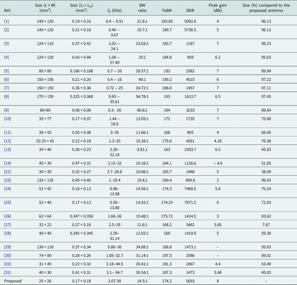
Using this BDR measurement and other comparative measures, a comparison study was carried out with other reported literature prototypes and summarized in Table 2. Results show that the proposed design is miniaturized by 7.67$\%$ compared to the smallest prototype and providecomparable gain than reported in the literature. The proposed antenna provides a wider BW compared to [Reference Liang, Zhong and Wang1–Reference Liu, Esselle, Hay and Zhong7, Reference Rafique and Din9, Reference Chen and Row10, Reference Samsuzzaman and Islam12, Reference Tang, Ziolkowski and Xiao13, Reference Srifi, El Mrabet, Falcone, Ayza and Essaaidi21, Reference Yeo and Lee23–Reference Rahman, Islam, Mahmud and Samsuzzaman27] and better BW ratio and $\%$
 BW compared to [Reference Chen and Row10, Reference Gorai, Karmakar, Pal and Ghatak11, Reference Tang, Ziolkowski and Xiao13, Reference Hakimi, Rahim, Abedian, Noghabaei and Khalily14, Reference Srifi, El Mrabet, Falcone, Ayza and Essaaidi21, Reference Okas, Sharma and Gangwar24, Reference Okas, Sharma and Gangwar25, Reference Rahman, Islam, Mahmud and Samsuzzaman27, Reference Okan28] with a higher BDR compared to all designs except for [Reference Okas, Sharma and Gangwar24, Reference Okas, Sharma and Gangwar25] but these present narrower BW, therefore not overcoming the proposed design.
Comparison study with the literature

Here, λl and λw are normalized length and width (in wavelengths) corresponding to the lowest operating frequency.
Time-domain analysis
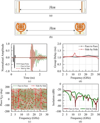
To measure the performance of the proposed antenna in time domain, a time-domain analysis was performed as arranged in Figs 10(a) and 10(b) and using two identical proposed antennas as the Tx and Rx. The normalized amplitudes of both input and output pulses for the two different configurations are shown in Fig. 10(c). There are no apparent ringing effects in the input and output signals (Fig. 10(c)) and just output signals decaying over the time. Fidelity factor (FF), which defines the cross-correlation between transmitted and received signals, is calculated using (2):

where S t(t) and S r(t) indicate transmitted and received signals and τ the group delay. The computed values of FF are listed in Table 3.
Time-domain analysis of the proposed antenna: (a) face-to-face configuration, (b) side-by-side configuration, (c) input and output signals, (d) group delay, (e) phase, and (f) isolation.

FF of the proposed antenna

Group delay is a measure of the transition time taken by the signal to pass through a device and it signifies the negative rate of transfer function phase with respect to the frequency [Reference Wiesbeck, Adamiuk and Sturm32]. Mathematically, group delay is expressed as

Simulated results of τg(ω) for both the configurations are shown in Fig. 10(d). Practically, for SWB antennas group delay should be within 1 ns [Reference Cho, Kim, Choi, Lee and Park33] to ensure the phase linearity in the far-field region and no pulse distortion is present.
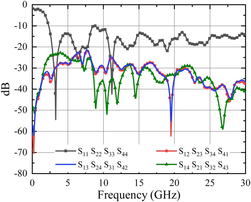
Isolation is defined by the ratio of incident power on input port and delivered power at the output port. This also characterizes the coupling between both the ports. A high value of magnitude of isolation, |S 21|, represents an uncorrelated transmission between the ports. The simulated response for both the configurations is shown in Fig. 10(f). It can be observed from the figure that S 21 ≤ −25 dB for the operating range.
Figure 10(e) shows phase variation of S 21 with respect to frequency. A linear variation of phase signifies that there is no out of phase component in the received signal within the operating range. For the proposed antenna, a linear variation of the phase is recorded within its operating range.
MIMO configuration
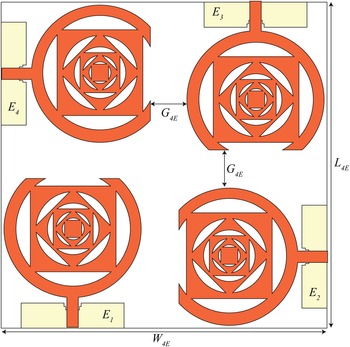
To exploit polarization diversity, the proposed antenna is arranged in a 4×4 MIMO configuration, next. Four elements, E i ∈ i = 1, 2, 3, 4, are etched on an FR-4 substrate of length L 4E = 56 mm, width W 4E = 56 mm, and thickness 1.6 mm with a structure shown in Fig. 11.
MIMO configuration for polarization diversity: L 4E = 56 mm, W 4E = 56 mm, G 4E = 5 mm.

A polarization shift between adjacent elements that form the array is 90° given the arranged orientation of these elements (Fig. 11). A gap, G 4E, of 5 mm is used between the adjacent elements to accord with the convention that gap ≥ λ/2 for low mutual coupling.
The simulated reflection coefficient and isolation of the array are given in Fig. 12 and show confirmation of the proposed SWB response (from 2.07 to 30 GHz) with isolation between ports ≥ 22.5 dB.
Simulated reflection coefficient and isolation.

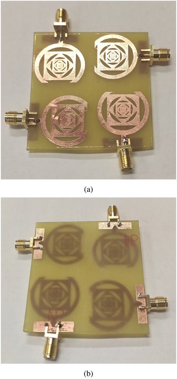
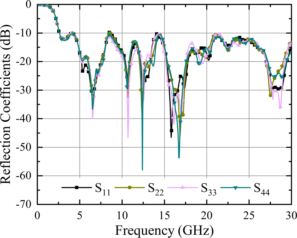
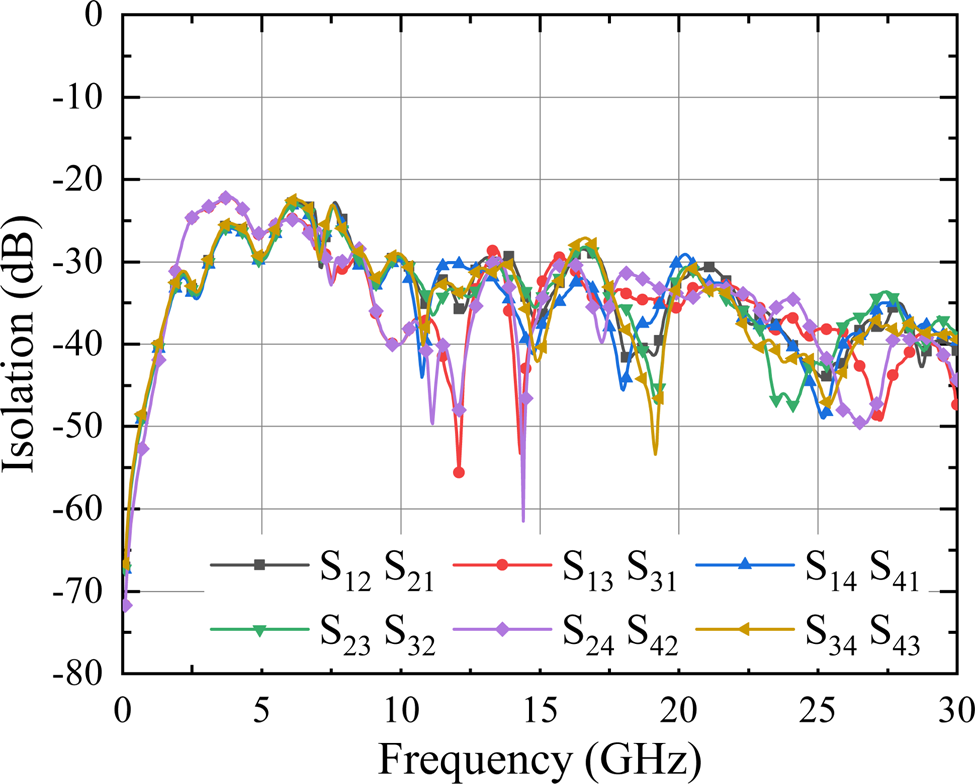
To validate the results, the prototype was fabricated. This is shown in Fig. 13 and the corresponding reflection coefficient and isolation between ports in Figs 15(a) and 15(b), respectively.
Fabricated prototype of 4 × 4 MIMO array: (a) front view and (b) back view.

Measured reflection coefficients of the array.

Measured isolation parameters of the array.

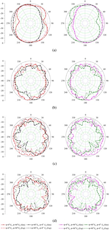
Measurements corroborated simulations; the insignificant discrepancies were due to fabrication tolerances. Since the proposed polarization diversity configuration has array elements which are arranged in a quadratic orientation, hence, the radiation characteristics are expected to mimic the same behavior. The E-plane (ϕ = 0°) radiation pattern of E 1 is therefore equal to H-plane (ϕ = 90°) radiation pattern of E 2 and vice versa. To validate this, the simulated and measured radiation patterns of the array at four distinct frequencies are shown in Figs 16(a)–16(d). It can be observed from the results that simulated and measured results are in good agreement and also satisfy the expected behavior of polarization diversity configuration.
Simulated and measured radiation patterns of the array at (a) 5 GHz, (b) 13 GHz, (c) 21 GHz, and (d) 28 GHz.

The performance parameters of the array are evaluated next.
Envelope correlation coefficient and diversity gain
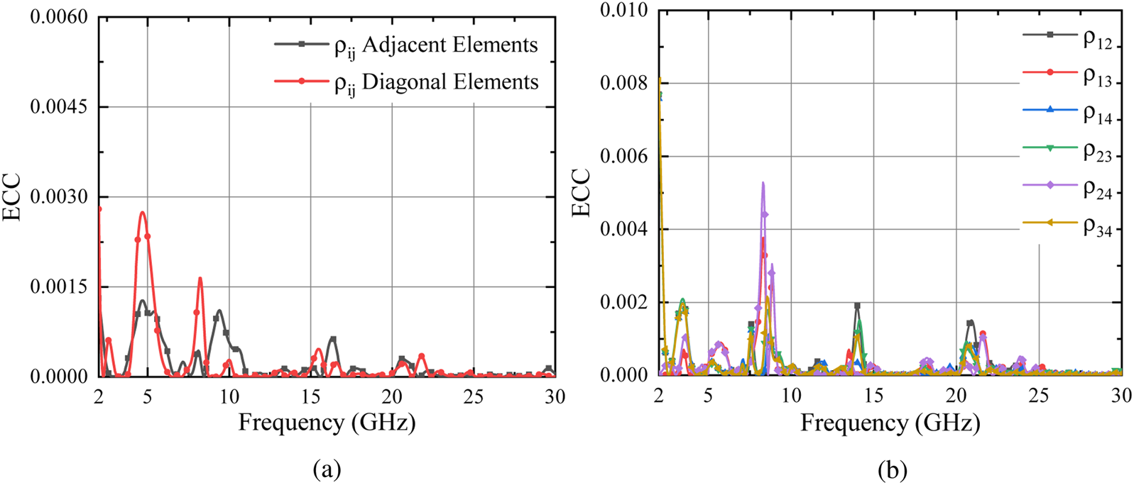
Envelope correlation coefficient (ECC) is one of the key parameters to evaluate the MIMO antenna performance that provides the degree of similarity between received signals. The ECC should ideally be zero and practically as low as possible within the operating frequency (f 0) range. The simulated and measured ECC performance of the 4 × 4 array is shown in Figs 17(a) and 17(b), respectively.
ECC performance of the array: (a) simulated and (b) measured.

In a uniform propagation environment, the ECC is formulated in terms of S-parameters [Reference Blanch, Romeu and Corbella34] as

In general, the ECC ≤0.5 is acceptable [Reference Koohestani, Moreira and Skrivervik35] signifying the admissible threshold level of signal distortion. From Fig. 17, it can be noted that simulated value of ρij for adjacent and diagonal elements is ≤ 0.0015 and ≤ 0.003 respectively. Furthermore, the measured values of ρij are ≤ 0.002 and ≤ 0.005 for adjacent and diagonal elements within the operating range. This shows that no signal distortion is present for the array (polarization diversity application). Additionally, low value of ECC indicates good isolation between the array elements, which in turn is helpful for simultaneous operation.
Diversity gain (DG) indicates the improvement obtained from MIMO compared to SISO (single-input single-output) and calculated by the following relation [Reference Chandel, Gautam and Rambabu36]

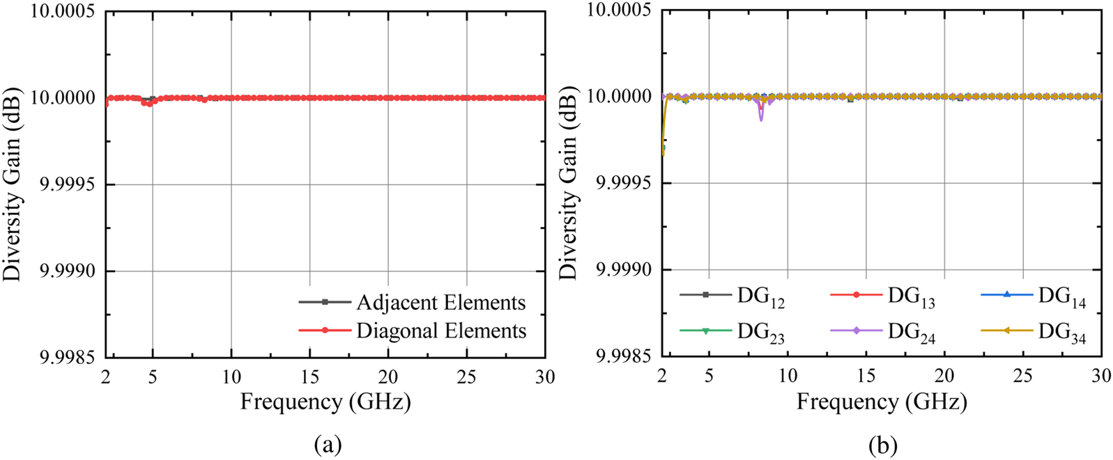
For satisfactory performance, DG ≥ 9.95 dB is desired [Reference Rafique, Agarwal, Nauman, Khalil and Ullah37]. The simulated and measured DG of the array is shown in Fig. 18 and is evident that DG ≈ 10 dB for both simulation and experimental results within the operating range.
Diversity gain of the array: (a) simulated and (b) measured.

Mean effective gain
The mean effective gain (MEG), in practice, is defined as the ratio of power received by MIMO antenna elements to the power received by an isotropic antenna under fading environment. Analytically, the MEG for different element ports can be computed [Reference Kumar, Ansari, Kanaujia and Kishor38] as following with mentioned acceptable limit:

and

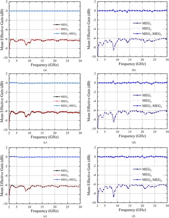
The simulated and measured values of MEG1 to MEG4, and the corresponding differences between different ports are plotted in Figs 19(a)–19(f).
Simulated and measured MEG of the array (a, b) between ports (1, 2), (c, d) between ports (1, 3), and (e, f) between ports (2, 4).

It is concluded from Fig. 19 that the difference between the MEG of two adjacent or diagonal array elements is below the acceptable limit of 3 dB.
Channel capacity loss
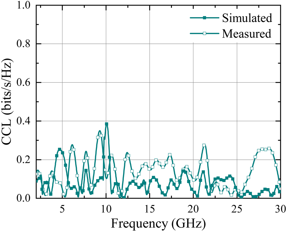
Channel capacity loss (CCL) denotes the highest transmission rate at which a signal can be continuously transmitted over a communication channel. For faithful transmission, the limit is 0.4 bits/s/Hz within the operating BW [Reference Choukiker, Sharma and Behera39]. The simulated and measured CCL of the array is shown in Fig. 20.
Simulated and measured CCL of the array.

From the results, it can be concluded that CCL falls within the acceptable limit for the entire operating band.
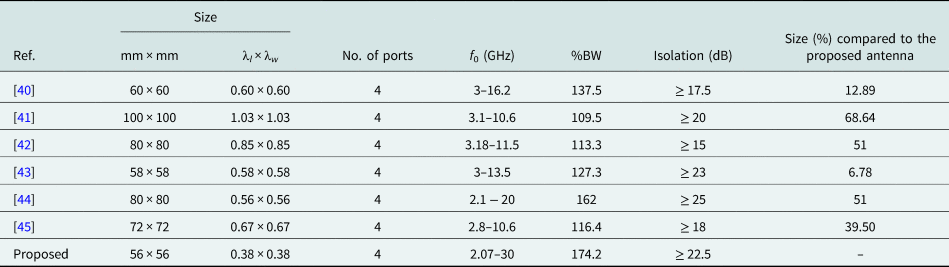
Table 4 shows a comparison study of the proposed array with the literature. Benefiting from compact SWB antenna elements proposed in this paper, the results show that proposed array is miniaturized by 6.78% compared to the smallest prototype [Reference Raheja, Kanaujia and Kumar43] with wider BW and comparable isolation compared to [Reference Wu, Yuan and Wu40–Reference Kumar, Lee, Kim, Mohyuddin, Choi and Kim45].
Comparison study of the proposed array with the literature

Here, λl and λw are normalized length and width (in wavelengths) corresponding to the lowest operating frequency.
Conclusion
A compact SWB annular ring antenna using 45° clock-wise square patch inclusions for SHF and polarization diversity applications is proposed. The antenna provided an SWB operation from 2.07 to 30 GHz with an FBW of 174.2$\%$ and a peak gain of 8 dBi and was experimentally validated. For the polarization diversity a 4 × 4 MIMO configuration was devised and manufactured, offering an effective isolation of ≥ 22.5 dB between ports. Its performance in terms of ECC, DG, MEG, and CCL was experimentally validated and found to be well within the specified limit.
Due to its compactness with prominent performance and relatively low cost design, the proposed antenna can be perceived as a suitable candidate for the SHF and polarization diversity applications where SWB is a must.
Acknowledgement
This work is supported in part by Department of Science and Technology (DST), Science and Engineering Research Board (SERB), Government of India under grant ECR/2018/000343.
 Shobit Agarwal received his Bachelor's degree in Electronics & Communication Engineering from Rajasthan Technical University (RTU), Kota, India in 2012 and his Master's in Electronics & Communication Engineering degree in 2016 from The LNM Institute of Information Technology, Jaipur, India. He served as one of the core members of the setup committee of the Antenna and Microwave Research Laboratory (AMR) at IIT Ropar with a vision of fabrication and testing capabilities of all the RF circuits and antennas operating up to 40 GHz and extendable to 110 GHz in future. His research area includes UWB and SWB antennas, MIMO systems, metamaterials, intelligent reflective surfaces, and frequency selective surfaces. He has authored number of research articles in reputed international journals and conferences. He is a graduate student member of the Institution of Electrical and Electronics Engineering (IEEE), USA; IEEE-Antennas and Propagation Society (IEEE-APS), USA.
 Ashwani Sharma received his Ph.D. in Antenna Engineering from the University of Deusto, Bilbao, Spain in 2015. He received a Master's degree in RF and Communication Systems from ETSIT, Technical University of Madrid (UPM), Spain in 2013, a B.Tech. degree in Communication and Computer Engineering from The LNM Institute of InformationTechnology, Jaipur, India in 2010. He is currently working as an Assistant professor at the Indian Institute of Technology Ropar, India, since July 2018. He was a visiting training fellow at the University of Kent, Canterbury, UK during May–August 2014, and a junior research fellow at the Indian Institute of Technology, New Delhi, India during 2010–2011. His research works have been published in various international journals and conferences such as IEEE Transactions and Letters, IET journals, and Wiley letters. His current research interests include exploiting field forming techniques in antenna design for wireless power transmission, IoT, and 5G.
 Ignacio Julio Garcia Zuazola completed his Ph.D. in Electronics (Antennas) part-time program in 2008; viva in 2010, University of Kent, Canterbury, UK, an eMBA in Business (part-time program) in 2016, Cardiff Metropolitan University, UK, a BENG in Telecommunications Engineering in 2003, Queen Mary – University of London, a HND in telecommunications engineering in 2000, North West London – University of Middlesex and an FPII in industrial electronics in 1995, School of Chemistry & Electronics of Indautxu, Spain. He has academic experience and been employed as Research Associate (2004) at University of Kent, Research Engineer, Grade 9/9 (2006) at University of Wales, Swansea, UK, Research Associate (2008) at University of Kent, Senior Research Fellow (2011) at University of Deusto, Bilbao, Spain, Visiting Senior Research Fellow (2011) at University of Leeds, UK, Research Associate (2014) at Loughborough University, UK, Representative of Spain (2015) at London School of Commerce, UK, and Lecturer in Electronic Engineering (2018) at University of Portsmouth, UK. He holds educational awards in electricity, pneumatic & hydraulics, and robotics and possesses relevant industrial experience, been hired for Babcok & Wilcox (1993), Iberdrola (1995), Telefonica (1997), Thyssen Elevators (1998), Cell Communications (2000), Nokia Bell Labs (2020), and Bilbao Ekintza – Bilbao City Council (2021). He engaged in an SME in electrical wiring (1996), and is currently a Senior Lecturer (2022) at London Metropolitan University (London Met), UK. He has included in Marquis Who's Who in the World 2010 edition and has published in international journals: IEEE Transactions, IET Proceedings and Electronics Letters. His current research interests include business development on one hand and single-band and multiband miniature antennas, and the use of electromagnetic-band gap (EBG) structures and frequency-selective surfaces (FSS). He led the antennas research line and supervised and mentored graduate and postgraduate students and currently bids for grants and contributes to the teaching, scientific, technological, and business development of London Met by promoting and increasing branding, research, and innovation. He is an MIET and an SMIEEE.
 Manoj Kumar received his B.Tech. degree from Punjab Technical University, Kapurthala, India, in 2016, and his Master's degree in Electronics and Communication Engineering from Kurukshetra University, Kurukshetra, India in 2018. He is currently working toward his Ph.D. degree with the Electrical Engineering Department, Indian Institute of Technology, Ropar, Rupnagar, India. His current research interests include RFID sensors, rectenna design, and base station antenna design.