Introduction
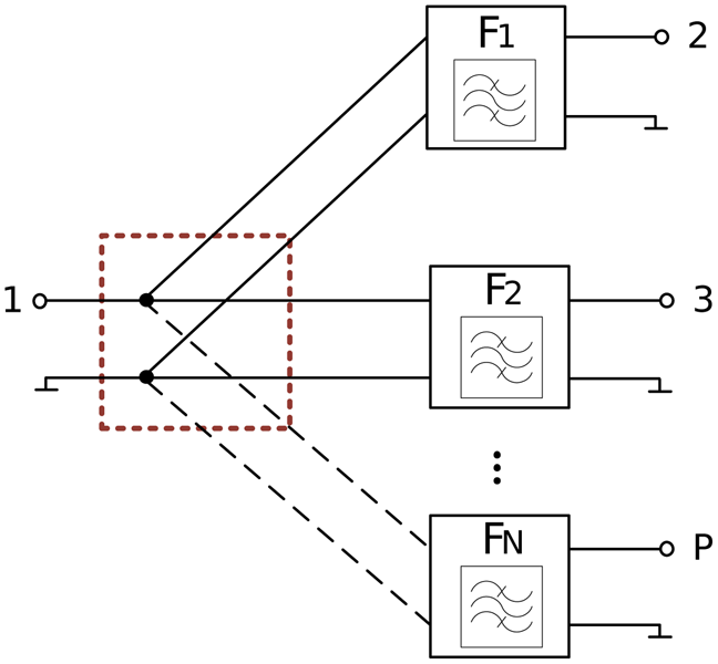
A general RF multiplexer is composed of N bandpass filters connected to a common node, usually an antenna through an N + 1 port junction. It results in a P ports network, as it is shown in Fig. 1. All filter channels are electrically connected to each other, so the combined loading effects produced by these filters must be considered in the early design stage.
General topology of an ideal star-junction P ports multiplexer.

Star-junction configuration is frequently used when the number of multiplexer channels is small in bulky technologies. This topology provides compact size, minimizing the total area of the multiplexer but shows a strong interaction among filters when these are individually designed with classical techniques and connected afterwards. Several works have proved general synthesis procedures that consider the multiplexer as a whole to overcome this situation [Reference Garcia-Lamperez, Salazar-Palma and Sarkar1–Reference Tamiazzo and Macchiarella3]. However, these methods are limited as the number of channels increases because of the round-off errors produced in the iterative procedure.
The loading effect due to the interaction between filters establishes the multiplexer system response; therefore, a numerical solution to evaluate the main multiplexer figures of merit like transmission, reflection, and multiport cross-isolation responses in early design stages is convenient and required.
In this work, a scattering matrix formulation for a nodal junction depending on the number of junction ports P, which allows evaluating multiport response in a numerical environment like MATLAB, is presented. The outcome is integrated with the S-parameter matrix of the filters attained through a general synthesis methodology presented in [Reference Giménez, Verdú and de Paco Sánchez4] to obtain the final matrix response of the multiplexer.
First, in section “Multiplexer scattering matrix definition”, a numerical nodal junction approach is developed, addressing the ideal junction matrix. The achieved results allow the acquisition of input/output multiport responses and the evaluation of technological constraints without needing external verification tools. Later, in section “Multiplexer design approach”, a multiplexer design approach based on minimum susceptance networks (MSN) definition is described. Under this interpretation, a recent published strategy [Reference Silveira, Verdú and de Paco5] to design star-junction multiplexers with the input reflection coefficient phase as a critical parameter is used for a triplexer example. Finally, an evaluation and discussion of an implemented lumped elements triplexer are presented in section “Triplexer example”. The very good agreement between the ideal and simulated star-junction matrix is illustrated, as well as the transmission, reflection, and cross-isolation triplexer responses.
Multiplexer scattering matrix definition
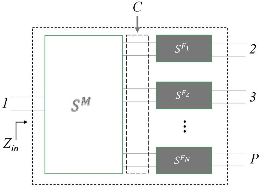
The multiplexer S-parameters are calculated considering the scattering matrices of the individually designed filters ($S^{F_{n}}$ ) and the junction (S M) as it is depicted in Fig. 2[Reference Cameron, Kudsia and Mansour6]. The scattering matrix of the overall multiplexer [S P] can be written as follows,

where the matrices S PP, S PC, S CC, and S CP represent the relation between external ports P and internal ports C of the network, and L is the connection matrix that relates the internal ports C. All these matrices are properly defined in [Reference Macchiarella and Tamiazzo2] and are linked to $S^{F_{n}}$ and S M. The external ports P define the scattering matrix of the multiplexer network.
N channel multiplexer.

Ideal star-junction matrix implementation
According to the selected topology of the multiplexer, Fig. 1 illustrates in dashed line, an ideal star-junction. This nodal idealization is useful as a representation of the node where incident power in port 1 is distributed to all filters. Taking into account its geometry, this network is reciprocal and ideally lossless.
Considering a star-junction of P (P = N + 1) ports, the circuit theory provides a direct scattering matrix solution. This solution is a first basic model to evaluate the ideal junction behavior of multiplexers with zero electrical length from the filters to the junction. It would be straightforward to introduce the electrical delay in the side of the filter or through a reference plane shift over the junction matrix elements.
To analyze the junction behavior, port 1 and internal ports C from Fig. 2 are loading with a reference impedance Z 0i, considering Z 01 = Z 02 = ...Z P = Z 0. The input impedance can be calculated as

resulting in a network that is not matched at any port since Z in ≠ Z0. The reflection coefficient at each port (S ii) is calculated substituting (2) in (3) and S ii is obtained as

For a lossless and passive device, its scattering matrix is unitary and

Considering the network symmetry, S ij = S ji; i ≠ j so

Substituting (3) in (5), S ij can be expressed as

Finally, since no electrical delay is considered due to the ideal nodal approach, no phase contribution is comprised. Then, the representing matrix of the P ports star-junction is defined as follows:

Filter matrix implementation
Once the junction matrix is obtained, it is necessary to compute the scattering matrix of each filter $S^{F_n}$ . The use of a systematic methodology approach that allows the evaluation of filter parameters in its first-tier yields good results for later optimization stages. As a consequence of the demanding specifications of the telecommunication standards, the use of filtering function with transmission zeros at finite frequencies is necessary.
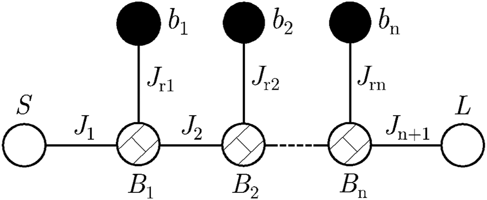
The methodology presented in [Reference Verdú, Evdokimova, de Paco, Bauer and Wagner7] addressed the filter synthesis with arbitrarily positioned attenuation poles at finite frequencies. The extracted-pole technique presented in [Reference Rhodes and Cameron8] and, more recently, the introduction of non-resonating nodes (NRNs) [Reference Amari and Macchiarella9] allows the synthesis of filters implemented by dangling resonant nodes (RN) and NRNs, suitably coupled to each other through an admittance inverter, J r. This configuration results in higher modularity and flexibility in the synthesis, making it possible to create fully canonical networks without a direct source-load coupling. The low-pass nodal representation is depicted in Fig. 3 where the NRNs are implemented by a frequency invariant reactance B i, and the RNs are represented by a unitary capacitor in parallel with a constant reactance b i. The RN–NRN pairs are coupled by admittance inverters J i.
Nodal diagram of a low-pass filter with dangling resonators.

For a defined set of transmission zeros (TZ), return loss level (RL), and filter degree (N), the scattering matrices of the filters individually designed $S^{F_n}$ are obtained following [Reference Giménez, Verdú and de Paco Sánchez4]. The reflection and transmission parameters are formulated as the ratio of two finite-degree polynomials and normalization constants ε and εr, where E(s), F(s), and P(s) are the characteristics polynomials of a generalized Chebyshev filtering function.

The phase term $e^{j \phi _{11}}$ introduces a shift in the original reflection coefficient phase. Since ϕ11 is a real quantity, the magnitude of S 11 is not affected. The proper calculation of this phase shift is essential to avoid the loading effect of the filters in duplexers and multiplexers, as will be seen later.
Multiplexer design approach
Most of the synthesis techniques related to multiplexers presented in the literature are based on iterative procedures or optimization techniques [Reference Wu and Meng10–Reference Yang, Wu, Yin and Yu12]. Both strategies demand significant computational time and resources. In general, designing multiplexers with an ideal star-junction configuration, where the interacting channel filters are directly connected in a common node, requires the proper combination of the imaginary part of the input admittance of all filters at the center frequency of each one as it is expressed in (9).

Thus, the combined loading effect produced by other filters is minimized, and additional immittance compensation networks are avoided. The fulfillment of this condition depends strongly on the value of the reflection coefficient phase shift ϕ11 of each filter.
The selection of the filtering function of each filter in multiplexers has been driven in the literature by the multiplexer classification as contiguous or not. Relying on this classification, there is a practical agreement for the use of doubly/singly terminated filters, respectively, in the early stages of the design for non-contiguous/contiguous channels [Reference Cameron, Kudsia and Mansour6].
For contiguous multiplexer designs based on singly terminated filters, dummy channels were required to imitate absent channels at the edges of the total multiplexer bandwidth, thus forming an additional annulling network for the compensation of the channel interactions. To avoid the addition of dummy channels or optimization techniques from the beginning, a direct approach is proposed in [Reference Silveira, Verdú and de Paco5] combining singly and doubly terminated filters independently designed under the MSN approach.
In [Reference Silveira, Verdú and de Paco5], it is established that in star-junction multiplexer configuration with N filters, inner filters (2:(N − 1)) are designed as MSN and outer filters (1 and N) are calculated as doubly non-MSN with the proper input phase adjustment. In case of MSN filters, ϕ11 = 0°. The phase calculation for non-MSN filters is made for channels 1 and N evaluating at the central frequency ΩC of the adjacent filters 2 and N − 1, respectively, as follows

Triplexer example
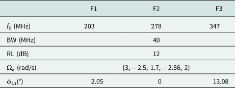
For a non-contiguous band triplexer example, the inner filter is designed as an MSN doubly terminated filter. The outer filters are calculated as non-MSN doubly terminated too, with the proper input phase adjustment. A triplexer compound of fully canonical 5th-order filters was designed. The synthesis input parameters are shown in Table 1.
Triplexer design specifications

Applying the theory developed before, S M can be obtained with (7), and $S^{F_{n}}$ is obtained with the synthesis methodology. Finally, the scattering matrix of the multiplexer S P is calculated applying (1). In the triplexer case, P = 4 and C = N = 3. The dimensions of each matrix are related to the quoted parameters above. The involved matrices in the matrix system for this example are expressed as

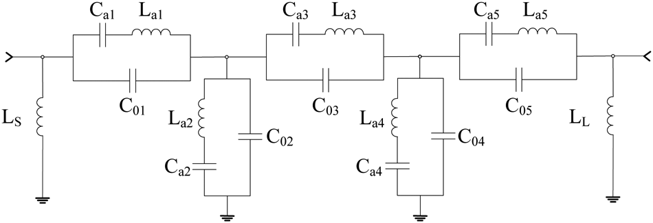
The proposed filter design methodology and the numerical analysis that has been conducted are technologically independent. Therefore, the experimental validation has been addressed using equivalent lumped reactance elements and microstrip technology for manufacturing simplicity. The dangling resonators in the low-pass model shown in Fig. 3 are transformed into bandpass domain, resulting in a ladder-type filter with resonators based on the Butterworth van Dyke (BvD) model. Figure 4 shows the equivalent electrical model of each channel. The input and output access lines of each filter were designed as 50 Ω lines. Its lengths were a priori fixed following a geometrical criterion and later integrated into the filter synthesis process due to its behavior as a phase shifter, in order to meet (9).
Circuital elements of 5th-order bandpass ladder-type filter based on the BvD model.

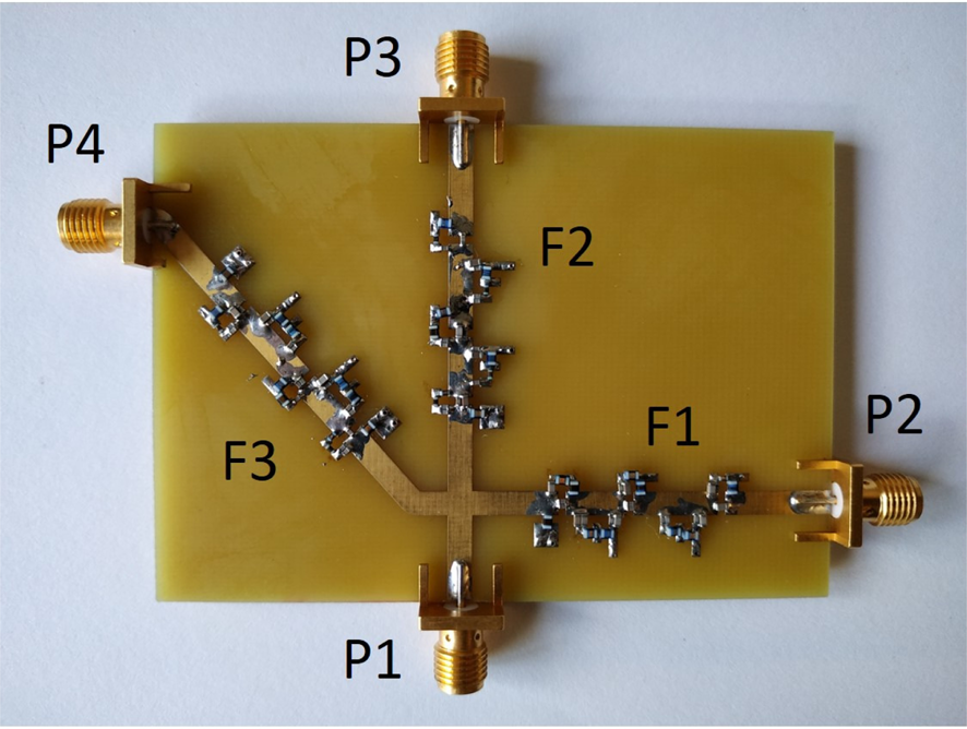
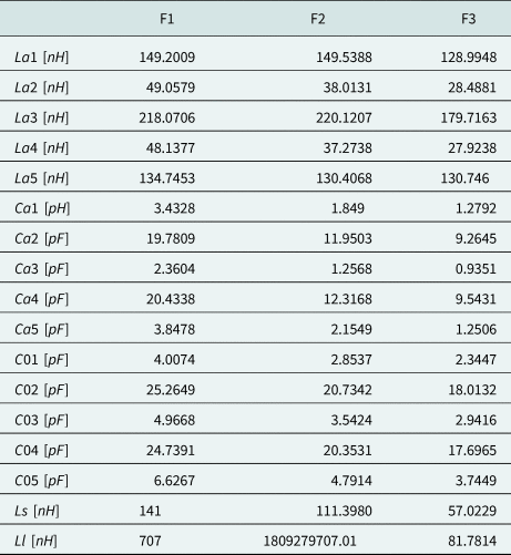
The synthesis procedure described in [Reference Giménez, Verdú and de Paco Sánchez4] provides the elements of the BvD model in the bandpass domain, allowing the fabrication of the prototype. Table 2 displays the synthesized values of the elements for each triplexer filter. Considering the available commercial values, most of the elements were split into two series inductors or parallel capacitors. The external parallel inductors (L S, L L) of filter F1 and F2 were dismissed because of its behavior as an open circuit at the triplexer frequency. The prototype manufactured in a single 1.52 mm-thick FR4 substrate is shown in Fig. 5. The triplexer has been accomplished using wirewound high-Q chip inductors and multi-layer high-Q capacitors from Johanson Technology. The inductors and capacitors Q-factor depends on the value of each element and the selected frequency; ranging from 35 to 45 for Q L (Q-factor of inductors) and 500 to 3000 for Q C (Q-factor of capacitors) for our design specifications.
Fabricated triplexer with lumped elements.

Bandpass elements of the Butterworth van-Dyke model for the triplexer filters

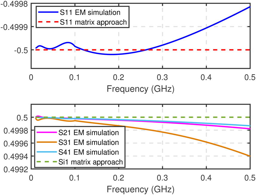
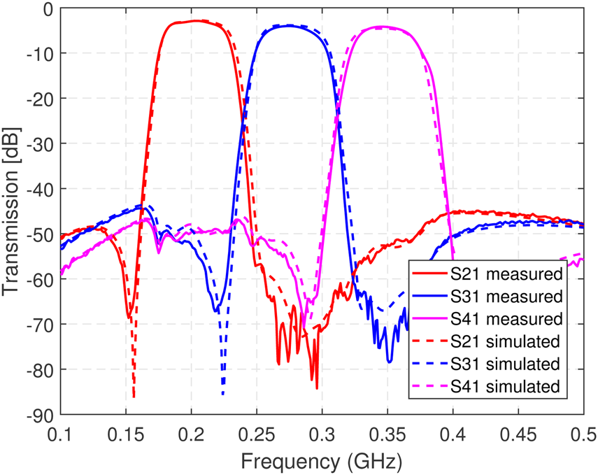
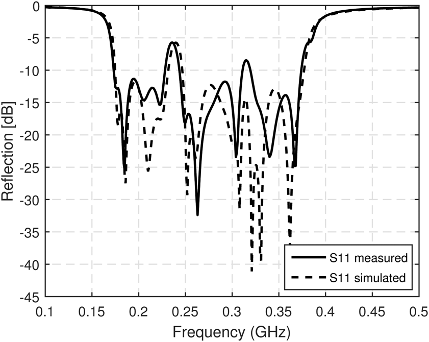
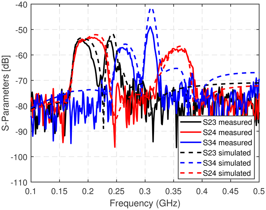
Electromagnetic simulation of the star-junction was carried out to evaluate the accuracy of (7). Figure 6 shows the excellent agreement between the solution obtained using the matrix approach and the simulation results. As expected, the higher the frequency, the higher the deviation from the theoretical value, but keeping very acceptable values to give an accurate result in the multiplexer response evaluation. The simulated and measured transmission, reflection, and cross-isolation responses are shown in Figs. 7, 8, and 9 respectively. As a consequence of the low Q-factor, especially Q L, the F1, F2, and F3 insertion loss are kind of high: − 2.89, − 4.05, and − 4.19 dB, respectively. The triplexer performance is not good, but still demonstrates the theory presented in this work. The technology and frequency range were chosen to help with a fast and easy manufactured proof of concept, but the developed theory can be applied at higher frequencies and other technologies where other effects should be considered.
S-parameters comparison between the star-junction electromagnetic simulation and the matrix approach.

Simulated and measured transmission triplexer response.

Simulated and measured reflection triplexer response.

Simulated and measured cross-isolation response.

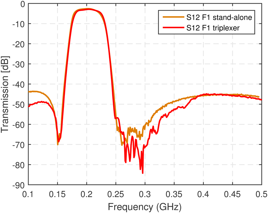
In order to demonstrate the minimization of the loading effect in the filter passband with the proposed methodology, filter F1 was measured detached from the triplexer. Figure 10 shows the excellent agreement between the measurements when the filter is part of the triplexer and when it is considered as stand-alone. In spite of the technology effects in the outcome, the experimental validation evidences the methodology accuracy to minimize the loading effect through the proper choice of ϕ11.
Comparison between the filter F1 transmission response when it is measured as stand-alone and connected as part of the triplexer.

Conclusion
A formulated numerical solution for the implementation of microwave star-junction multiplexers based on a matrix approach has been presented. Taking into account the reciprocal and lossless properties, and considering the symmetry and unitary conditions, a closed scattering matrix formula was found for an ideal star-junction multiplexer dependent on the port number of the junction P. This solution is a first approximation to evaluate the behavior of multiplexers in a numeric simulation environment. Also, a practical approach for multiplexer designs is discussed in this work combining doubly terminated filters independently designed under the MSN point of view.
A non-contiguous bands triplexer was manufactured. The minimization of the interaction between filters was observed, endorsing the proposed multiplexer approach. Even though the introduced result only considers the ideal star-junction connection, it states a simple starting point through the circuit theory for the characterization of more complex junctions in any technology.
Acknowledgements
This work is supported by Ministerio de Ciencia, Innovación y Universidades (MCIU), la Agencia Estatal de Investigación (AEI) y el Fondo Europeo de Desarrollo Regional (FEDER) under grants TEC2015-69229-R and RTI2018-096019-B-C33.
 Patricia Silveira was born in Havana, Cuba, in 1989. She received the B.S. degree in Telecommunications and Electronics Engineering (with honors) and the M.S.degree in Telecommunications and Telematics from Technological University of Havana, Havana, Cuba, in 2012 and 2016, respectively. In 2016, she joined the Antenna and Microwave Systems (AMS) group of Universitat Autònoma de Barcelona (UAB), under the Telecommunications and Systems Engineering Department. Her main research interests include the computer-aided design of microwave filters and multiplexers, synthesis techniques, and BAW and SAW devices.
 Jordi Verdú was born in Sabadell, Spain,in 1980. He received the M.S. degree in Telecommunication Engineering and the Ph.D. degree (cumlaude) from the Universitat Autònoma de Barcelona (UAB), Barcelona, Spain, in 2006 and 2010, respectively. From 2006 to 2010, he was a member of the Antenna and Microwave Systems (AMS) Group, Universitat Autònoma de Barcelona. In 2010, he joined the RF System Group, European Spallation Source in Bilbao (ESS-B), Bilbao, Spain, where he was the Group Coordinator. From 2011 to 2012, he was with the École Polytechnique Fédérale de Lausanne, Switzerland, supported by the Marie Curie Grant. In 2013, he joined the Theory Signal Communication Group, UPC. In 2015, he became a Visitant Professor at the Universitat Autònoma de Barcelona. He has participated in several national and international projects, mostly related to the design of acoustic wave filters. His current research interests include the design of microwave devices and linear modeling. Dr. Verdú is also a member of the MTT-2 Microwave Acoustics Technical Committee. He received the Department Best Thesis Prize from UAB.
 Pedro de Paco was born in Badalona, Spain. He received the M.S. degree in Telecommunication Engineering and the Ph.D. degree (cum laude) from the Universitat Politècnica de Catalunya (UPC), Barcelona, Spain, in 1997 and 2003, respectively. In 1998, he joined the Electromagnetic and Photonics Engineering Group (EEF), Signal Theory and Communications Department (TSC), UPC, with a grant from the Institut d'Estudis Espacials de Catalunya (IEEC), Barcelona, in a joint activity related to the European scientific space mission Planck. He was a member of the LFI-Radiometer, Noordwijk, working group and the Planck Consortium, Noordwijk, The Netherlands. During his Ph.D. degree at UPC, he participated in several national and international research projects, mostly related to microwave and millimeter-wave circuits and systems applied to design and testing of remote-sensing instruments and front-end point-to-multipoint broadband communication systems. Since 2004, he has been an Associate Professor with the Universitat Autónoma de Barcelona (UAB), Barcelona, where he teaches applied electromagnetics and microwave engineering courses. From 2018 to 2019, he was a Visiting Researcher with the Microwave and RF Research Group, University of Colorado at Boulder, Boulder, CO, USA. He has been appointed as a Technical Expert for Telecommunications Equipment by the National Agency of Accreditation, Madrid, Spain. His current research interests include microwave and microwave acoustics filter synthesis and design, as well as microwave and radar systems and devices. Dr. de Paco Sánchez serves as a member of the Technical Review Board for the European Microwave Conference.