I. INTRODUCTION
For hundreds of years, most of structural metallic materials, such as steels and aluminum alloys, have been mainly based on one principal element as the matrix with the addition of other minor elements for property/processing enhancement, thereby vastly limiting the number of applicable alloy systems and development of new materials. A novel class of alloys designated as high-entropy alloys (HEAs) was posited since 1995.Reference Murty, Yeh and Ranganathan1–Reference Yeh, Chen, Lin, Gan, Chin, Shun, Tsau and Chang4 Differing from traditional alloys based on one or two major elements, HEAs may contain five or more principal metal elements with the concentrations of each element being between 5 and 35 at.%.Reference Murty, Yeh and Ranganathan1–Reference Yeh3,Reference Chuang, Tsai, Wang, Lin and Yeh5–Reference Miracle and Senkov12 For traditional alloys, increasing the number of alloying elements promotes formation of intermetallic compounds and may promote formation of complex microstructures that may degrade mechanical response to applied stress and the environment. By contrast, HEAs predominantly consist of admixtures of simple face-centered cubic (FCC), body-centered cubic (BCC), and/or hexagonal close packed solid solutions due to their high configurationally entropy of mixing.Reference Zhang, Yang and Liaw6,Reference Ma and Zhang7,Reference Zhang, Fu, Zhang, Wang, Wang, Wang, Zhang and Shi13,Reference Lee and Shun14
As a consequence of the four core HEA effects (i.e., high-entropy effects, severe lattice distortion, sluggish diffusion, and cocktail effect), well-designed HEAs can possess unique performances including high strength, high hardness, high wear resistance, excellent corrosion resistance, high resistance to temperature softening, and superior magnetic properties.Reference Tong, Chen, Yeh, Lin, Chen, Shun, Tsau and Chang15–Reference Lin and Tsai23 Currently, the majority of studies mainly focus on optimizing mechanical properties of HEAs. One example is to add Al to FCC HEAs such as AlxCoCrFeNiReference Hsu, Juan, Sheu, Chen and Yeh19,Reference Wang, Wang, Wang, Tsai, Lai and Yeh24,Reference Yang, Xia, Liu, Wang, Liu, Zhang, Xue, Yan and Wang25 and (FeCoNiCrMn)100−xAlxReference He, Liu, Wang, Wu, Liu, Nieh and Lu9 to balance the ductility and strength. The increase of Al contents promoted the formation of ordered BCC phase (i.e., B2 phase) and accordingly increased the strength at the cost of reduced ductility for both AlxCoCrFeNi and (FeCoNiCrMn)100−xAlx HEA systems.
Certainly, the tribological behavior of materials is very important for a wide variety of industrial applications. In particular, HEAs can benefit from what is known about wear compliant and wear-resistant materials in their design and execution. For example, Wu et al.Reference Tong, Chen, Yeh, Lin, Chen, Shun, Tsau and Chang15,Reference Wu, Lin, Yeh, Chen, Huang and Chen26,Reference Liu27 studied the adhesive wear behavior of AlxCoCrCuFeNi HEAs. It was found that the high Al contents led to high hardness and resulted in a large improvement in wear resistance of the HEA in sliding wear. The increase of Al contents promoted the formation of AlNi-type B2 intermetallics and increased the volume fraction of the BCC phase, increasing the resistance against plastic deformation and enhancing the wear resistance. Meanwhile, Chuang et al.Reference Chuang, Tsai, Wang, Lin and Yeh5 investigated the wear behavior of a series of AlxCo1.5CrFeNi1.5Tiy alloys in comparison with the conventional wear-resistant tool steels (SUJ2 and SKH51). The results indicated that the performance of Co1.5CrFeNi1.5Ti and Al0.2Co1.5CrFeNi1.5Ti HEAs was at least two times better than that of SUJ2 and SKH51 with similar hardness. Liu et al.Reference Liu, Ma, Gao, Zhang, Zhang, Yang, Wang and Qiao28 examined the effect of environment on the tribological behavior of AlCrCuFeNi2 in ambient air, deionized water, and rain water. It was found that the deionized water and simulated rainwater acted as the lubricant and cooling liquid, resulting in significantly lower wear rates than that in ambient air. The simulated rainwater also acted as corrosive solution, contributing to the lowest wear rate. The dominating wear mechanisms of HEAs in ambient air were adhesive wear leading to fragmentation of the oxide and contributing particles at the interface that led to abrasion. In the simulated acid rain conditions, the wear mechanisms were wear-corrosive with subsequent abrasion due to delamination of oxides.
The wear characteristics of a material is an important property in many applications, for example, rotating machinery, wire ropes, electrical contacts, anchor chains and other metal on metal contact, etc. It is inevitable that many materials will be exposed to a variety of environmental conditions among them outdoor exposure where humidity is high, saltwater environments whether on ships or in coastal regions where salt fog can leave residue on the surface, etc., and for each of these conditions, the mechanical interaction due to wear can accelerate an already deleterious tribological situation. Moreover, frictional heating and sliding velocity must be taken into account. In this study, the tribological properties of Al0.6CoCrFeNi HEAs were investigated in the ambient air, deionized water, simulated acid rain, and simulated seawater under a variety of externally imposed tribological variables.
In this study, the tribological properties of Al0.6CoCrFeNi HEAs were investigated in the dry air, deionized water, acid rain, and seawater with different sliding velocities. The Al0.6CoCrFeNi HEA was chosen in the present study because it exhibits balanced strength and ductility and hence may be important for structural materials’ applications.Reference Hsu, Juan, Sheu, Chen and Yeh19,Reference Wang, Wang, Wang, Tsai, Lai and Yeh24,Reference Yang, Xia, Liu, Wang, Liu, Zhang, Xue, Yan and Wang25
II. EXPERIMENTAL
Alloy ingots with a nominal composition of Al0.6CoCrFeNi were prepared by arc-melting a mixture of pure elemental metals (purity >99 wt%) in a Ti-gettered high-purity argon atmosphere with a water-cooled copper mold. To achieve a more homogeneous distribution of elements in the alloys, the samples were remelted five times and flipped for each melt. After the last melting sequence, melted alloys were eventually dropcast into a copper mold with a size of 80 (length) × 10 (width) × 2 mm (thickness) flat plates.
The as-cast alloys were sliced into small rectangular specimens with the dimension of 10 × 5 × 2 mm. The rectangular specimens were ground in sequence using a series of ever finer abrasive papers starting at 360 # and finishing with 2500 #. Final polishing was accomplished using 0.2-μm diamond. The dilute aqua regia ( ${V_{{\rm{HN}}{{\rm{O}}_{\rm{3}}}}}{\rm{:}}{V_{{\rm{HCl}}}} = 1{\rm{:}}3$) was used to etch the microstructure for phase observation and characterization.
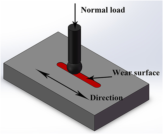
The friction and wear tests were performed using a ball-on-block high speed reciprocating wear-test apparatus (MFT-R4000, Zhongke Kateke Industry & Trade Co., Ltd. Lanzhou, China) at room temperature (a schematic view as is shown in Fig. 1). The tested samples were rubbed against a hardened GCr15 steel ball (Baoshan Iron and Steel Group, Shanghai, China; weight percent ωCr = 1.30% ∼ 1.65%, the hardness is 727 HV) with a diameter of 5 mm. The wear experiments were carried out under the dry-sliding condition, deionized water, simulated acid rain (PH = 2), and simulated seawater (weight percent ωNaCl = 3.5%), respectively. The chemical composition of the simulated acid rain is listed in Table I, and the composition is ‘in line’ with the yearly average rain fall ingredient in the city of Taiyuan, China. The normal load was 5 N with different frequencies at 2, 3, 4, and 5 Hz. The reciprocating amplitude and sliding time were fixed to 5 mm (half cycle) and 1800 s, respectively. Then, the experiments were carried out at a room temperature of 298 ± 2 K (25 ± 2 °C) and with a relative humidity of 55 ± 5%. The steel ball and block specimens were cleaned in the acetone before and after each wear test. The steel ball was replaced by a new one after each wear test.
Schematic view of wear specimens.

The main ion composition in the simulated rainwater.

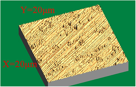
The friction coefficient was monitored continuously by using a load cell mounted on the ball holder in conjunction with a chart recorder during wear tests. Good reproducibility on the friction–coefficient curves was observed in this study. The volume loss of the alloys was calculated by measuring the depth and width of the wear scars, using a three-dimensional (3D) surface profiler, based on scanning the white-light interferometers. The wear rate was obtained by the wear volume loss divided by time during wear tests. The microstructure and chemical composition of the present HEAs, the wear surface, and wear debris were analyzed, using a scanning electron microscope (SEM) with an attached X-ray-energy-dispersive spectrometer (EDS). The crystal structure was characterized using an X-ray diffractometer (XRD) with the Cu Kα diffraction generated at 40 kV and 40 mA. The scanning range was from 20° to 90° in 2θ at a scanning rate of 3°/min. Vickers hardness tests were performed with a load of 9.8 N, and a load cycle time of 15 s. The result was averaged from nine random points across the specimen surface. The surface roughness was obtained using a FM-Nanoview 6600 (FeiShiman Precision Instrument Co., Ltd. Suzhou, China). Figure 2 displays a three-dimensional topographic map of the sample surface with an average roughness of 15.7 nm.
Three-dimensional topography of the sample surface.

III. RESULTS
A. Microstructure and hardness
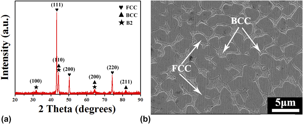
Figure 3 shows the XRD plot and SEM image of the as-cast Al0.6CoCrFeNi HEA. Only simple FCC solid solution and BCC/B2 structures were observed, agreeing with a prior study by Wang et al.Reference Wang, Yang, Yang, Zhang, Ma and Qiao29 It was reported that only the FCC solid solution was obtained at composition levels x ≤ 0.4, the BCC phase was detected when x ≥ 0.5, and the FCC phase disappeared when x ≥ 0.9.Reference Lin and Tsai23–Reference Yang, Xia, Liu, Wang, Liu, Zhang, Xue, Yan and Wang25,Reference Wang, Wang and Yeh30
(a) XRD pattern and (b) SEM image of Al0.6CoCrFeNi.

The increase of the Al content not only promotes the formation of BCC solid solutions but also increases lattice distortion since an Al atom has a significantly larger atomic radius than a Co, Cr, Fe, or Ni atom (the atomic volume of Al, Co, Cr, Fe, and Ni is 10.00, 6.70, 7.23, 7.09, and 6.60 cm3/mol, respectively).Reference Wang, Wang, Wang, Tsai, Lai and Yeh24 The mixing enthalpies between Al and transition metalsReference Hsu, Juan, Sheu, Chen and Yeh19 Ni, Co, Fe, and Cr are −30, −24, −10, and −6 kJ/mol, respectively, suggesting strong attractive binding force between Al and transition metals. The mixing enthalpies between transition metals themselves, such as Cr–Ni, Cr–Co, Cr–Fe, Co–Fe, Fe–Ni, and Co–Ni pairs, are 3, 8, 13, 13, 12, and 17 kJ/mol, respectively, and these values suggest repulsive binding forces between them. Besides, the atomic size of Al is the largest in these elements (The atomic volume of Al, Co, Cr, Fe, and Ni is 10.00, 6.70, 7.23, 7.09, and 6.60 cm3/mol, respectively).Reference Wang, Wang, Wang, Tsai, Lai and Yeh24 As a matter of fact, the hardness of the AlxCoCrFeNi alloy increases from 120 to 740 HV with increasing the Al contents (i.e., from x = 0 to 2). The microhardness of Al0.6CoCrFeNi alloys reaches 280 HV.
B. Wear-test results
1. Friction coefficient
The friction coefficient is calculated by the following equationReference Kobe31:
 $$\mu = {c \over {\sqrt {\alpha \left( {1 - {c^2}} \right)} }}\quad ,$$
where α is the constant (α = 9), and c is a coefficient, which is less than 1. Equation (1) indicates that μ decreases rapidly with decreasing c. Meanwhile, the ultimate shear strength of the oxidation film on the surface of the metal material can be expressed as τf = cτb, where τb is the ultimate shear strength of the substrate.Reference Wang, Yang, Yang, Zhang, Ma and Qiao29 Moreover, the oxidation film was hard and brittle. Therefore, its ultimate shear strength was lower than that of the substrate. When the oxidation film was destroyed, the value of c increased to nearly 1.
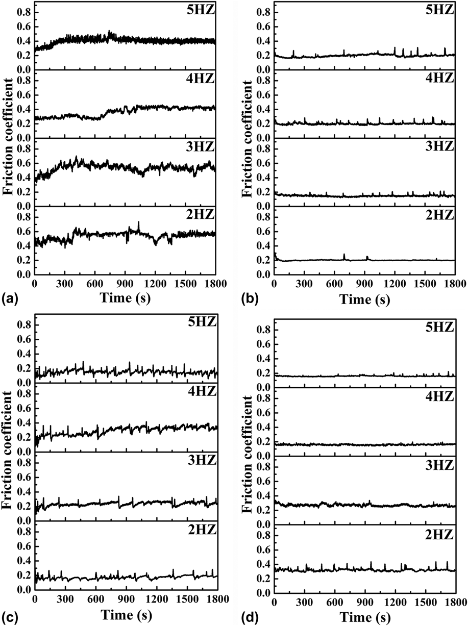
Figure 4 displays the variation in friction coefficient with sliding time at various sliding frequencies in ambient air, deionized water, simulated acid rain, and simulated seawater. It can be seen that the friction–coefficient curve in the ambient air condition can be divided into two stages (i.e., before and after 450 s of cyclic test time). In the first part (i.e., t ≤ 450 s), the value of the friction coefficient gradually rises up to a peak value due to the settling down of the indenter and the breaking-in of the worn surface for HEAs to that of the steel counterpart. This stage is the so-called running-in period. Subsequently, some narrow periodic waves with a large fluctuation can be observed due to the periodic accumulation and elimination of the debris on the worn surface in Fig. 4(a). The stick-slip phenomena (i.e., spontaneous jerking motion) occurred in sliding wear, and there was a transfer of material during the back and forth process between counterfaces. Subsequently, the material was hardened, making it less ductile. Also, the fatigue cracks formed during the continuous sliding process. At some points, a small piece of wear debris was separated and entrained at the interface between the two bodies. Therefore, the hard oxidized debris caused the abrasion. In addition, more debris accumulated and the particles got larger, leading to the more severe abrasion.
Friction coefficient of HEAs at the frequencies of 2, 3, 4, and 5 Hz in different conditions: (a) ambient air condition, (b) deionized water, (c) the acid rain, and (d) seawater.

2. Wear rate
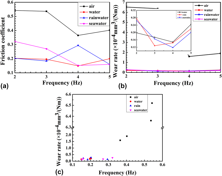
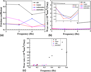
The mean friction coefficient and wear rate of the as-cast Al0.6CoCrFeNi HEA in different environments and frequencies are summarized in Table II and also displayed in Fig. 4. The property parameters of materials that are used for calculating the friction coefficient and wear rates are listed in Table III. The wear rate in the dry condition is much higher than those of other environments. It is found that the highest wear rate is 6.52 × 10⁻⁴ mm3/(N m) at 2 Hz and decreases with increasing the frequency in dry condition. Then, there is a sharp decline in wear rate at 4 Hz and reaches a minimum of 1.58 × 10⁻⁴ mm3/(N m). Subsequently, the wear rate increases slightly. Further discussions are included in Sec. IV.A and IV.B.
Average friction coefficient and wear rate of Al0.6CoCrFeNi HEAs under different environments and frequencies.

Properties of the materials used in calculations.Reference Ligrani, Subramanian, Craig and Kaisuwan49,Reference Incropera53

IV. DISCUSSION
A. Effect of frequency and environment
The friction coefficient and wear rate first decrease sharply till 4 Hz and then increase slightly at 5 Hz with increasing the frequency as shown in Figs. 4 and 5. This trend is largely related to the oxide film formed on the worn surface. The generation of the oxide film becomes faster with increasing the frequency at lower frequencies, decreasing the friction coefficient. However, the oxide film and lubrication film are severely damaged and the worn surface becomes coarser at higher frequencies. According to the above analysis, the formation of the oxidation film at lower frequencies results in a reduction in the friction coefficient, whereas at higher frequencies, the oxidation film is destroyed, and the value of c in Eq. (1) increases. Hence the friction coefficient increases. However, the friction coefficient curve indicates some broader waves with smaller fluctuation amplitude and exhibits a steady state in aqueous conditions.
Wear properties of Al0.6CoCrFeNi in ambient air condition, deionized water, acid rain, and seawater: (a) Friction coefficient versus frequency, (b) wear rate versus frequency, and (c) wear rate versus friction coefficient.

The friction coefficient in the liquid environment is remarkably lower than that in ambient air. This is mainly caused by two factors. The first is the rinsing effect of liquid. The surrounding liquid was circulating during the reciprocating movement of the steel ball. Therefore, the wear debris and smaller particles accumulated on the worn surface were removed, making the worn surface smoother. The second is the cooling effect of aqueous solutions. The frictional heat in dry sliding resulted in the softening of the matrix and generated a high friction coefficient. The curves are smoother in the deionized water and seawater than those in ambient air condition and the acid rain (see Fig. 4).
The variation of wear rates in the liquid environment is not significant, as the frictional heat was absorbed by the solution. However, the wear rates in the simulated acid rain and simulated seawater are lower than that in the deionized water. This can be explained by two possible factors. The first was the difference in the lubrication effect. The lubrication action of the acid rain and seawater for the HEAs was better than that in the deionized water, which decreased the abrasion of the surface.Reference Wang, Yang, Yang, Zhang, Ma and Qiao29,Reference Wang, Yang, Yang, Zhang and Qiao32 The second is the corrosive effect of the acid rain.Reference Lin, Qiang, Zou, Guo, Li, Yuan, Yong, Wang, Wang and Tang33,Reference Lin, Liu, Zou, Li, Yuan, Wang and Tang34 Small particles and debris were corroded into tiny powders that can polish the worn surface during sliding, which can be compacted to form a protective film under the action of the loading force and sliding velocity, thus reducing the volume loss.
B. Calculation of the frictional heat
When two bodies slide against each other with a relative speed (v) and a contact pressure (P), the frictional heat is generated at the interface, which results in severe thermomechanical damage of materials to some extent.Reference Decuzzi and Demelio35–Reference Gurskii and Chichinadze43 Note that only a part of the work done by the friction force is then transformed into the frictional heat. Another part of the work is dissipated by materials in the form of the potential energy (ξ) used for forming wear debris, resulting in the cracks and plastic deformation. A larger value of ξ represents more severe wears. According to the energy-wear theory,Reference Suh, Jahanmir, Abrahamson and Ernest44,Reference Rigney and Hirth45 the potential energy only accounts for 9–16% of the total energy. Therefore, the frictional heat can be calculated by the following equation:
 $$Q = \int_{{t_1}}^{{t_2}} {\left( {1 - \xi } \right)} \mu \left( t \right)Fv{\rm{d}}t\quad ,$$
where the friction coefficient μ(t) is a function of time since it is sensitive to the surface-roughness during sliding, F is the friction force, and v is the velocity.
The heat flux, q, can be deduced by the definition:  $q = {Q \over {tA}} = \left( {1 - \xi } \right)\mu pv$.Reference Blok36–Reference Yevtushenko and Chapovska39,Reference Gurskii and Chichinadze43 Combining with the above analysis (the detailed analysis process was provided in the Appendix), the heat flux in the local area, q 2, can be calculated:
 $${q_2} = {{\sqrt {{\lambda _1}{\rho _2}{c_2}\left[ {1 - \exp \left( { - {v \over {4{\alpha _2}}}\sqrt {{F \over {\pi {H_2}}}} } \right)} \right]} } \over {\sqrt {{\lambda _1}{\rho _2}{c_2}\left[ {1 - \exp \left( { - {v \over {4{\alpha _2}}}\sqrt {{F \over {\pi {H_2}}}} } \right)} \right]} + \sqrt {{\lambda _2}{\rho _1}{c_1}\left[ {1 - \exp \left( { - {v \over {4{\alpha _1}}}\sqrt {{F \over {\pi {H_1}}}} } \right)} \right]} }}\left( {1 - \xi } \right)\mu pv\quad .$$
Many studies reported that some Ni-based alloys and FCC HEAs are characterized using Ni as reference partly because Ni is chemically similar to other transition metals such as Co and Fe. Moreover, Ni is miscible with Al, Fe, Cr, and other metal elements.Reference Wu, Bei, Otto, Pharr and George46–Reference Zhao and Nieh48 The density of the Al0.6CoCrFeNi HEA is measured to be 7.2 × 10³ kg/m3, but its thermal conductivity and heat capacity are not known. Therefore, the data of pure Ni is used instead of approximation. The thermal diffusion coefficient can be obtained from α = λ/cρ,Reference Ligrani, Subramanian, Craig and Kaisuwan49 and other constants are listed in Table III.
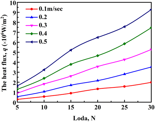
The relationship among the heat flux, normal loads, and sliding speeds is shown in Fig. 6. The heat flux increases distinctly with increasing the speeds and loads. This trend indicates that a higher speed or load will lead to a greater amount of the frictional heat, a higher contact-surface temperature, and a faster rate in forming the oxidation film. Therefore, the metallic wear debris was oxidized more quickly. Additionally, it is expected that the wear rate decreases with increasing the frequency. However, as the temperature continues to rise, the surface of samples is softened and the plastic deformation is aggravated by the steel ball, resulting in the increase of the wear rate.
Value of heat flux with the velocity and normal load.

C. Worn surface and wear mechanisms
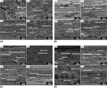
Figure 7 shows the SEM images of the worn surface of the Al0.6CoCrFeNi HEA under different testing conditions and frequencies. Many large wear particles, oxide debris and particles, and the deep grooves parallel to the sliding direction are presented in Fig. 7(a) (in the ambient air condition). Moreover, the plastic deformation and many large cracks can be detected in Figs. 7(a1) and 7(a2). The delamination of a large amount of materials can be observed in Figs. 7(a3) and 7(a4). In contrast to Fig. 7(a2), the crack in Fig. 7(a1) is larger, which demonstrates that the amount of wear decreases with increasing the frequency. Figure 7(a3) shows that the surface morphology is greatly improved, and large cracks disappear. Moreover, the worn surface is covered with grooves and delamination, accounting for the protective role of the oxidation film. The morphology in Fig. 7(a4) is approximately consistent with that of Fig. 7(a3). Nevertheless, the wear scratches and grooves are deeper, and there is much wear debris distributed on the worn surface. The wear scars and fragments demonstrate the wear mechanisms of abrasive wear as well as delamination and oxidation wear. It can be concluded that the surface in Fig. 7(a3) is optimal in line with the consequence of the friction coefficient and wear rate. Thus, the wear resistance at 4 Hz is the highest in the ambient air condition.
SEM images of the worn surface under different conditions. The figure label indicates the test condition [(a) ambient air, (b) deionized water, (c) acid rain, and (d) seawater] and the applied frequencies (2, 3, 4, and 5 Hz).

Whereas in the liquid environment, the wear tracks displayed on the worn surface are smoother. The cracks can hardly be detected. Moreover, the debris and grooves are observed only in limited regions. Besides, there are some dark areas seen in Figs. 7(b)–7(d) due to the lubricating and cooling effects. The heat concentration, local stress, and friction of shear decreased in the liquid environment, thus inhibiting the generation of cracks and debris. Furthermore, most of debris and particles were washed away by the liquid during the sliding process, which alleviated the abrasive wears. Therefore, the frictional properties in the liquid environment are much better than that in the ambient air condition. Moreover, the frictional heat promotes the desquamation of the materials from the matrix. While the frictional heat is smaller but not negligible, the effect of the flash temperature on the wear property in sliding is greater than that of the apparent temperature of the contact surface in mild sliding conditions, which leads to the occurrence of minor delamination in the liquid environment.
The morphology of the friction surface in the deionized water is similar to that in the ambient air condition, suggesting similar wear mechanisms operating in both cases. Relative to the ambient air grinding, the deionized water only played a role of lubricating and cooling. In other words, it mitigated the wear to a certain degree, and the wear mechanism was not changed fundamentally. Some cracks and plastic deformation can be observed in Fig. 7(b1), which suggests the cracks opening and plastic deformation. In Figs. 7(b2) and 7(b4), evident grooves, delamination, and some debris (marked in white color) are detected, indicating the characteristics of abrasive and delamination wear, as well as minor oxidation wear. Moreover, there are spots of dark areas found on the worn surface, which reveals the adhesive wear from Fig. 7(b3). The highest wear resistance in the deionized water was obtained at 4 Hz as well.
However, the wear mechanism was changed in the corrosion liquid solution. In fact, the corrosion-wear occurred in the corrosive fluid, forming the oxidation film. Subsequently, the oxides were broken down and the wear debris was generated during the wear testing. Moreover, the friction heat was generated on the interface, leading to the formation of additional oxides. The morphology of the worn surface in the acid rain is exhibited in Fig. 7(c). The crack and plastic deformation are not observed, and the size of debris and particles is smaller than that of Fig. 7(b). Additionally, shallow and narrow furrows are observed in Figs. 7(c1) and 7(c4), which indicates that slight abrasive wear occurred. The wear surface in Figs. 7(c2) and 7(c3) is relatively smooth, and abundantly dark areas can be detected, revealing a mechanism of adhesive wear. The composition of the acid rain is listed in Table I, mainly containing the hydrogen ion (10 × 10−3 mol/L) and chlorine ion (0.022 × 10⁻³ mol/L). Hence, the dominant corrosion mechanism is the hydrogen-ion corrosion, accompanied by the chlorine-ion corrosion. The corresponding chemical reaction isReference Lin, Bai, Liu, Tang and Yang50
 $${\rm{Me}}\left( {{{\rm{O}}^{2 - }},2{{\rm{H}}^ + }} \right) + x{\rm{C}}{{\rm{l}}^ - } \to {\rm{MeC}}{{\rm{l}}_x} + {{\rm{H}}_2}{\rm{O}}\quad .$$
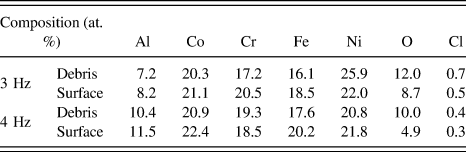
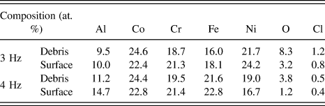
Large debris was corroded into small particles or even powders, mitigating the abrasive wear remarkably. The average chemical compositions of the debris and worn surface in acid rain are listed in Table IV. The debris on the worn surface has higher oxygen and chlorine element contents, which indicates that the debris experienced more severe oxidation and corrosion. Furthermore, the content of the chlorine element at 3 Hz is higher than that at 4 Hz, implying that more severe corrosion occurred at 3 Hz. Figures 7(c1)–7(c4) indicate that the quality of the worn surface was optimal at 4 Hz and the worst at 2 Hz.
Measured composition from EDS analysis of the wear debris and worn surfaces of Al0.6CoCrFeNi HEAs in the simulated acid rain.

The morphology of the worn surface in the seawater [Figs. 7(d1)–7(d4)] suggests that the wear mechanisms are identical to those in acid rain [Figs. 7(c1)–7(c4)], but the chlorine-ion corrosion plays a leading role in seawater environment, contributing to the different wear resistance of the alloy in these two environments. The chloridion occupied the position of oxygen ions by penetrating into the passive film. In addition, the substitution of chloridion for oxygen ions reduced the negative charge of the initial position of the oxygen ions, thereby increasing the number of oxygen vacancies with a larger chloridion radius. This process accelerated the migration and reaction of chloridion at the metal-oxide interface.Reference Wang, Jiang, Zheng, Ke, Sun and Wang51 Hence, the structure of the oxide film changed, and peeling pits formed under the action of stress. These chlorides are easily hydrolyzed to produce hydrogen ions and intensify the corrosion. The chlorine ion is hard to penetrate into the oxide film owing to the dense structures and corrosion resistant of Al2O3 and Cr2O3. By contrast, hydrogen ions can be directly dissolved into the oxide film. Hence, the corrosion resistance of the Al0.6CoCrFeNi HEA in the seawater was higher than that in the acid rain (also see Tables IV and V).
Measured composition from EDS analysis of the wear debris and worn surfaces of Al0.6CoCrFeNi HEAs in the simulated seawater.

It is evident that the content of iron decreases with increasing the chlorine content. In the corrosion solutions, iron is preferentially dissolved. In addition, Cr and Al are rapidly oxidized to form a passive film to resist the attack of chlorine.Reference Wang and Chao52 Therefore, the iron content can indicate the degree of corrosion. Tables IV and V show that the degree of corrosion was the smallest and the resistance of wear was highest at 4 Hz in the seawater consistent with the results of the friction coefficient and wear rate. In the chloride solutions, the polishing effect of fine and soft particles became more apparent with increasing the frequencies. However, when the frequency continued to increase to a too high level, the peeling pits formed on the oxide film, which were attributed to the corrosion mechanism of chlorine, resulting in the increased wear.
V. CONCLUSIONS
In this study, the microstructures and tribological properties of the Al0.6CoCrFeNi HEA were investigated in the ambient air condition, the deionized water, simulated acid rain, and simulated seawater at 2–5 Hz frequencies. The frictional heat was calculated and discussed. The following conclusions were reached:
(1) The as-cast Al0.6CoCrFeNi HEA contained simple FCC and BCC solid-solution phases. The hardness value was 280 HV. The heat flux of the HEAs (q 2) increased with increasing the velocity and normal load.
(2) The average friction coefficients of the HEA in the ambient air condition were the highest (0.542, 0.536, 0.365, and 0.402) and that in the simulated seawater was the lowest (0.322, 0.270, 0.152, and 0.160) at frequencies of 2, 3, 4, and 5 Hz, respectively. The wear rate and friction coefficient of the HEA decreased first and then increased with increasing the frequency.
(3) The wear rate of the as-cast HEA in the ambient air condition was higher than that in the liquid environment. The lowest wear rates were 0.118 × 10⁻⁴ mm3/(N m) in the seawater, 0.128 × 10⁻⁴ mm3/(N m) in the acid rain, and 0.148 × 10⁻⁴ mm3/(N m) in the deionized water.
(4) The dominant wear mechanisms of the as-cast HEA were severe abrasive wear, delamination wear, and oxidative wear in the ambient air condition. The dominant wear mechanism in the deionized water was abrasive wear, accompanied by the delamination and slight adhesive wear.
(5) The corrosion-wear occurred in the corrosive fluid, leading to the formation of the oxidation film. The wear mechanisms of the as-cast alloys in simulated acid rain and simulated seawater were abrasive wear, oxidative wear, adhesive wear, and corrosion wear. The corrosion resistance of the HEA in the seawater was higher than that in the acid rain.
Supplementary Material
To view supplementary material for this article, please visit https://doi.org/10.1557/jmr.2018.279.
ACKNOWLEDGMENTS
J.W.Q. would like to acknowledge the financial support from the State Key Lab of Advanced Metals and Materials (No. 2016-ZD03). P.K.L. would like to acknowledge the National Science Foundation (DMR-1611180), the Department of Energy (DOE), Office of Fossil Energy, National Energy Technology Laboratory (DE-FE-0008855 and DE-FE-0024054, and DE-FE-0011194), with Dr. Farkas, Mr. V. Cedro, Mr. R. Dunst, and W.J. Hullen as program managers. M.C.G. acknowledges the support of the US Department of Energy’s Fossil Energy Cross-Cutting Technologies Program at the National Energy Technology Laboratory (NETL) under the RES contract DE-FE-0004000.