I. INTRODUCTION
Wrinkles or folds are ubiquitous in nature and often regarded as an undesirable defect.Reference Cerda and Mahadevan1,Reference Genzer and Groenewold2 When membranes are exposed to compressive strains, they typically respond already at rather low stresses by a so called buckling instability.Reference Chan, Kundu, Lin and Stafford3,Reference Santangelo4 The membrane deforms perpendicular to the stress direction and thus wrinkles are formed. In spite of their omnipresence, wrinkles have received comparably little attention by scientists for a long time. This is mainly due to the fact that buckling processes underlying wrinkle formation are instabilities that can only be described by nonlinear theories. Often an analytical description is not possible which limits accessibility to specialists. However, this spontaneous pattern formation is becoming increasingly attractive as a simple method to produce surface structures in microscale that does not require predefined photo-masks or templates due to the periodic nature of wrinkles.Reference Schweikart and Fery5–Reference Li, Cao, Feng and Gao7 Moreover, these processes are interesting for their pattern complexity as well as ease of formation with a dominant periodicity. The processes that underlie the formation of these spectacular patterns are usually governed by a physical instability whose evolution results in the selection of a characteristic wrinkling length scale. This length scale is often determined because of a compromise between two or more competing physical processes that favor structure formation on different length scales.
Recently, most studies have focused on bilayers with a rigid thin film on top of a compliant substrate, and it inherently leads to uniform and periodic patterns in prestrained substrates and thickness ratio of layers and therefore surface instability. It is believed that a relaxation process of the excessive stress which accumulated in the bilayer system obtains surface instability.Reference Genzer and Groenewold2,Reference Ma, Mannino, Wagner and Kloxin8–Reference Sun, Xia, Moon, Oh and Kim11 Many of research groups had proposed the well-ordered wrinkling process by unique strain configuration, resulting from the material properties and stress distribution of their systems.Reference Huang, Hong and Suo10,Reference Bowden, Huck, Paul and Whitesides12–Reference Chen and Hutchinson14 Among them, the most often used method is to pre-stretch the elastomer substrate mechanically or thermally to create ordered wrinkles on the thin film. Generally, the induced wrinkles are perpendicular to the direction of the strain, and the prestrain deformation determined the configuration of wrinkles such as wavelength, amplitude, and so on. However, a bilayer system based on an elastomeric substrate is not suitable for many applications that require surface micro-structuring on the surface such as superhydrophobic surfaces,Reference Im, Im, Lee, Yoon and Choi15,Reference Gaillard, Hendrus and Vogt16 adhesion patches,Reference Jeong, Kwak and Suh17,Reference Rodríguez-Hernández18 and lens arraysReference Kim, Lee, Na and Lee19,Reference Kim, Kim, Na, Lee and Lee20 due to some issues such as mechanical stability and material requirements.Reference Kang, Na, Moon, Il Lee, Yoo and Lee21,Reference Kim, Kim, Ṕgard, Oh, Kagan, Fleischer, Stone and Loo22
Recently, various methods have been demonstrated for the fabrication of microscale structures on solid substrates, including nanoimprinting,Reference Steinberg, Runkel, Papenheim, Wang, Mayer and Scheer23–Reference Tan, Gilbertson, Chou, Faircloth, Rohrs, Tiberio, Ruoff and Krchnavek25 surface relief gratings,Reference Kubo, Ikutame, Takei, Weibai, Ikeda, Yamamoto, Uraji, Misawa, Fujioka, Kaiju, Zhao and Nishii26,Reference Eggert, Bourdon, Nolte, Rischmueller and Imlau27 and electro-spinning.Reference Martial and Hartell28,Reference Studart and Erb29 Although these methods had demonstrated sophisticated microscale patterns with multiple directional order and gradients of amplitudes on conventional substrates, high process cost and long process time were issues to overcome. Therefore, it is necessary to develop new methods to ensure high stability and well-ordering on solid substrates since conventional thin film processes are based on solid substrates.
In this paper, we demonstrated a new concept of micro-pattern formation processes in liquid crystalline polymer (LCP) films through utilizing simple plasma treatment. The proposed method achieves well-organized spontaneous wrinkles having two-dimensional ordering and multiple domains in a large area without any template and/or elastomeric substrate. Since the LCP incorporated the optical anisotropic mesogenic groups into polymer chains, which used here, it has a liquid crystal (LC) phase in films and it can be utilized for optic applications requiring a microscale pattern on the surface.
II. MATERIALS AND METHODS
A. Material preparation
The liquid crystalline solution of RMS03-001C (Merck, Darmstadt, Germany) having mesogenic groups was used to achieve the periodic wrinkling process. A commercial material of RMS03-001C is a photo-polymerisable mixture for the preparation of +A optical symmetry birefringent polymer films in optics and display fields.Reference Na, Park, Sohn and Lee30,Reference Na, Kim, Sohn and Lee31 It is composed of four different acrylate-based monomers including 4-(6-acryloyloxyhexyloxy)-benzoic acid (4-cyanophenyl ester), 4-(3-acryloyloxypropyloxy)-benzoic acid 2-methyl-1,4-phenylene ester, 4-(6-acryloyloxyhexyloxy)-benzoic acid-(4-methoxyphenylester), and 2-methyl-1,4-phenylene-bis[4-(6-acyloyloxyhexyloxy)benzoate], and it is dissolved in propylene glycol monomethyl ether acetate (PGMEA).
B. Definition of orientation of wrinkling
As the LC molecules interact chemically (and/or mechanically) on an alignment layer and anchor along the predefined direction, thereby forming homogeneously aligned LC, which is parallel to the rubbing direction, the LC molecules in RMS03-001C could also define molecular ordering by using an alignment layer.Reference Na, Pae, Kim, Yu and Lee32–Reference Takahashi, Yoon and Parrish35 Here, we used poly(vinyl alcohol) (PVA) as an alignment layer, and it is widely used to promote uniaxial ordering in the nematic phase LC.
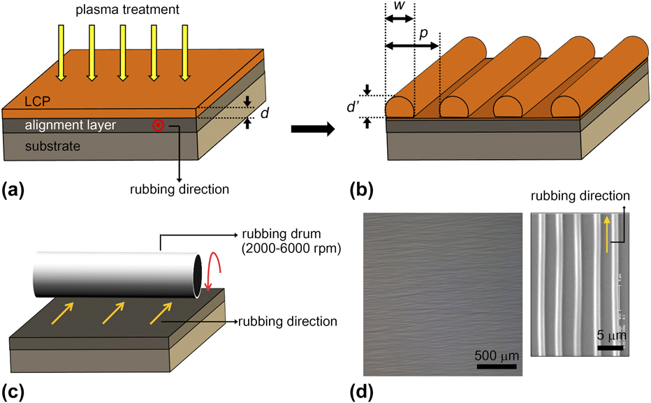
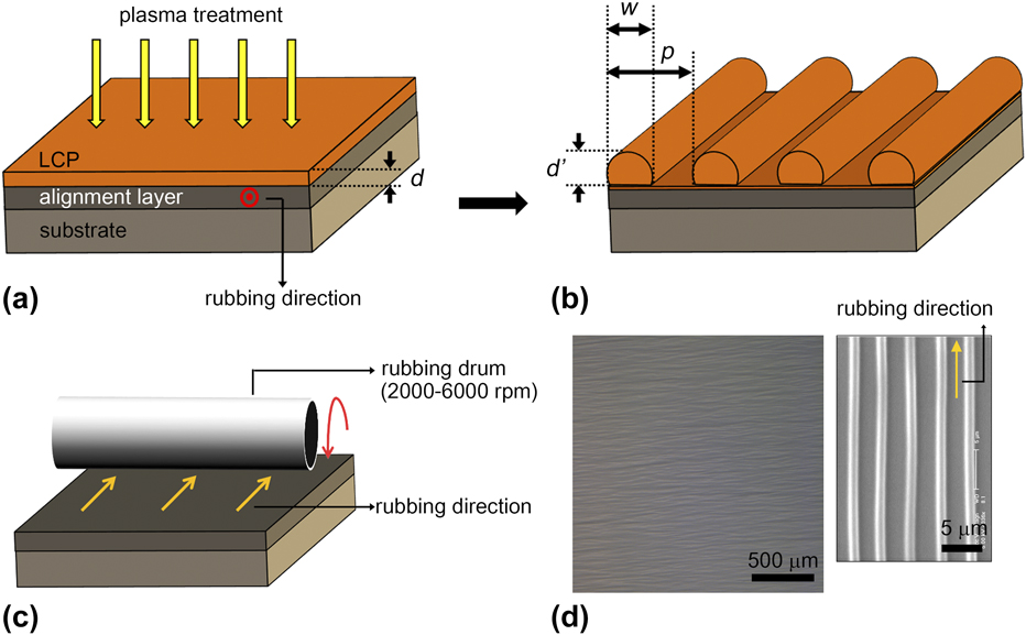
To form an alignment layer, 3 wt% PVA in water was first spin-coated (3000 rpm for 60 s) on a glass substrate and baked at 150 °C for 90 min. After fully drying, the PVA film on the substrate was rubbed unidirectionally to promote homogeneous alignment (see Fig. 1). According to the groove theory of Berreman, the rubbing process could create the microscale groove (see Fig. S1) along the rubbing directions on the buffed PVA surface.Reference Huang, Lin, Wang, Huang, Tsai and Fuh36 Here, to promote alignment of LC, we used a rubbing cloth (thickness 1.8 mm, Hyperflex Co., Hyperflex, Gumi, South Korea) made of cellulose strands (sheath-core 11 μm).
Schematic diagrams of the anisotropic wrinkling process with a unidirectional rubbing technique: cross-sectional images of (a) the initial film and (b) the wavy surface after plasma treatment. Here, d and d′ represent the initial film thickness and the amplitude of wrinkle, respectively. w and p show the width and the period of the wrinkle pattern, respectively. (c) The unidirectional rubbing process by a rubbing machine. (d) Images of the LCP wrinkles of an optical microscope (left) and a SEM (right).
In this paper, we aim to implement multi-domain wrinkles and it should require spatial segmentation and a selective rubbing process for each domain. Previously, we developed a multi-rubbing procedure, also called the stamping-assisted rubbing (SAR) technique based on the protective layer of Novec EGC-1700 (3M, St. Paul, Minnesota).Reference Koo, Na, Kim, Li and Lee37,Reference Na, Li, Park and Lee38 EGC-1700 is a fluorinated acrylate polymer carried in a hydrofluoroether (HFE) solvent that does not chemically affect the alignment layer of PVA. It is found that EGC-1700 was used without causing any mechanical and chemical damage to the first rubbed alignment layer. The SAR technique helps the secondary rubbing process through the selectively covered region of the alignment layer. To generate bidirectional LC alignment, a patterned protective layer on a predefined stamp of poly(dimethylsiloxane) (PDMS) was transferred onto the first rubbed alignment layer and was cured at room temperature in a minute. After forming the protective layer on PVA, the second rubbing process was performed on the regions not covered what we want to make the wrinkle direction. Note that the first aligned domain (covered region) keep their alignment properties, such as angle and anchoring force, during the second rubbing process. Finally, the protective layer should be dissolved in the HFE, and bidirectional alignment was readily achieved. If it needs more than two different ordered domains, we should do repeat this SAR procedure with a preferred patterned stamp.
C. Wrinkling formation
When RMS03-001C was coated on the rubbed PVA film, the liquid crystalline molecules of RMS03-001C, which came into contact with the PVA layer were aligned along the rubbing direction and formed a uniaxial ordering in the nematic phase. Since RMS03-001C was in a PGMEA solution (3 wt%), the spin-coated thin film was heated at 60 °C for 1 min to remove the residual solvent. Note that the ordering of LC could be simply verified by using an optical polarizing microscope. To perform wrinkle formation, the coated RMS03-001C films on the alignment layer were exposed to plasma treatment. Here, the chamber-based plasma system (Cute, Femto Science Co., Hwaseong, South Korea) was used for plasma treatment. Oxygen (O2) and argon (Ar) were used as the reactive gas, and the flow rates were 20 and 7 sccm, respectively.
Figure 1 shows the surface wrinkling process on a homogeneously aligned PVA film. Previously, we had seen the phenomena of a surface wrinkling through the plasma treatment.Reference Kang, Na, Moon, Il Lee, Yoo and Lee21 In the plasma treatment, the LC monomer solution on the alignment layer crosslinked from the top surface due to the propagation of the free radicals.Reference Yasuda and Wang39 As freely moving LC monomers come close and cross-link with each other, the skin shrinks or its stress-free state shrinks. Then, the skin relieves stresses by out-of-plane deformation to produce wrinkles due to the difference in the thermal-expansion coefficients between the rigid skin on top and the soft unpolymerized layer on the bottom. Further curing solidifies the remainder of the LCP film and sets the wrinkle patterns. After fully crosslinking, unidirectional wrinkling patterns evolved on the RMS03-001C film surface uniformly across a few square centimeters scale area. Here, d and d′ the depicted initial film thickness and amplitude of wrinkling after plasma treatment, respectively, and w and p were the width and period of the single wrinkle as shown in Figs. 1(a) and 1(b). The morphology of the LCP wrinkles was examined using an optical microscope (DM750P, Leica, Seoul, South Korea) and scanning electron microscope (SEM, S-5000; Hitachi, Seoul, South Korea).
III. RESULTS AND DISCUSSION
A. Single domain anisotropic wrinkling
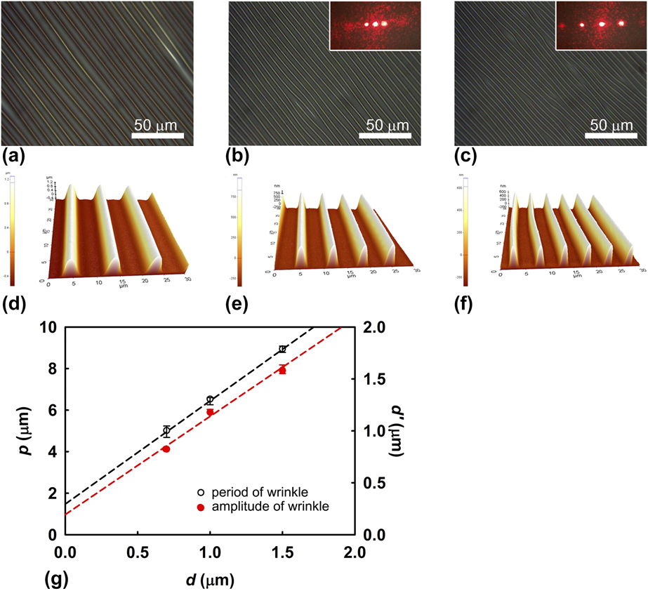
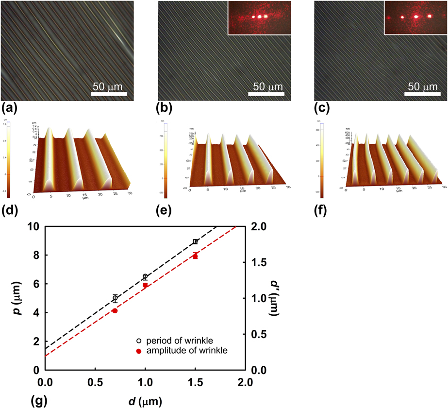
First, to examine the relationship between the thickness of the coated LC monomer film and geometric dimension of wrinkles, the thickness of the LC monomer film was controlled by the spin-coating speed of RMS03-001C from 2000 to 6000 rpm. The initial film thickness was measured by atomic force microscopy (AFM, XE-100, Park Systems, Suwon, South Korea), exhibiting a range of 0.7–1.5 μm-thick film while keeping the plasma treatment condition including time, gas flow, and power.Reference Na, Park, Sohn and Lee30,Reference Na, Kim, Sohn and Lee31
Figures 2(a)–2(c) show the single domain anisotropic wrinkle pattern as a function of initial thickness (d). Each inset of Figs. 2(b) and 2(c) depicts the images of the laser diffraction pattern; these results showed the well-ordered periodicity of the anisotropic wrinkle pattern, and the period of wrinkles reflected the interval of each diffracted beam. Here, a He–Ne laser (λ = 632.8 nm) was used as a light source to measure the light diffraction. In addition, atomic force microscope (AFM) images of Figs. 2(d)–2(f) verified the geometry of wrinkling in more detail and we could see uniform single domain wrinkles. Therefore, well-defined wrinkling patterns in various thicknesses also reflect that single domain alignment was well maintained over a sufficiently wide range of film thicknesses as shown in Fig. 2(g). Consequently, this result has shown that the initial thickness of the film before plasma treatment probably would be one of the critical control factors to define the period (p) and amplitude (d′). Note that the sinusoidal waveform of wrinkles was transformed into a rectified sinusoidal waveform as an increase in d′ because the valleys of the wrinkle reached the flat substrate in the case of sufficient plasma treatment. In addition, this rectified sinusoidal waveform could have an advantage for realizing the clear optical grating effect. Previously, Stafford and co-worker had reported a relationship between moduli, thickness, and induced instability in multilayer systems,Reference Chan, Kundu, Lin and Stafford3 and the results show that the structure of wrinkling was proportional to the thickness ratio of a soft substrate (H)/skin film (h). In our case, the thickness of the skin layer should be constant, since it is governed by plasma treatment. Therefore, our result showed agreement with previous research that period (p) and amplitude (d′) increase accordingly with the increasing initial film thickness (d).
Unidirectional surface wrinkling: (a)–(c) optical and (d)–(f) AFM images of the wrinkle pattern as a function of the initial thickness of the LC monomer film. The changes in amplitude and period show the effect of the initial film thickness on the morphology of the wrinkle. Each inset of (b) and (c) shows the diffraction pattern image depending on the period of wrinkle. (g) Geometrical changes in wrinkles. Here, d is the initial film thickness and d′ and p depicted the amplitude and the period of wrinkle pattern, respectively.
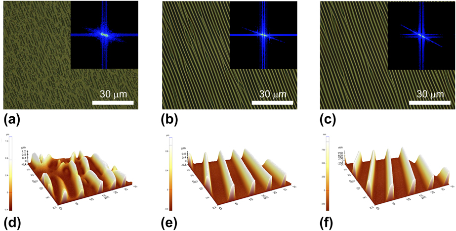
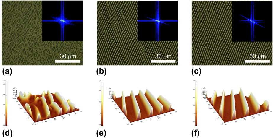
To characterize an effect of rubbing strength on the alignment layer, we fabricated the anisotropic wrinkle formation with various rubbing conditions. Figure 3 shows that anisotropic wrinkles depend on the rubbing speed [(a) 200, (b) 1000, and (c) 3000 rpm], and the rubbing strength increases as the rubbing speed per unit time increases.Reference Huang, Lin, Wang, Huang, Tsai and Fuh36,Reference Koo, Na, Kim, Li and Lee37 Figure 3(a) shows a microscope image of a sample rubbed at 200 rpm and it can be seen that the wrinkles are un-uniform and broken. It is shown that the rubbing condition is not sufficient to form a uniform wrinkle. On the other hand, it could be observed that uniform wrinkles were formed in the samples rubbed at 1000 and 3000 rpm as shown in Figs. 3(b) and 3(c). The fast Fourier transform (FFT) on the image process is used to gain information about the geometric structure of the spatial domain image, and it is a good image processing tool, which is used to decompose an image into its sin and cos components. Each inset of Figs. 3(a)–3(c) shows the image of FFT depending on the wrinkle morphology. According to the distributivity law, the FFT image obtains the strong anisotropy with increasing rubbing speed. In the case of the sample rubbed at low speed, an irregular wrinkle pattern is formed which is attributed to a low anchoring force. As the rubbing speed increases, the PVA layer has a strong anchoring force and a uniform wrinkle pattern can be formed as shown in Figs. 3(d)–3(f). Therefore, all subsequent experiments proceeded with a sufficient rubbing speed (2000 rpm) to have a uniform wrinkling structure.
Wrinkles versus rubbing strength: optical microscopy images of the wrinkles induced by the plasma treatment of LCP films. LCP films prepared on the alignment layer having different rubbing conditions such as (a) 200, (b) 1000, and (c) 3000 rpm. Each inset shows the image of FFT. (d)–(f) Show the AFM images of (a)–(c).
B. Bi-directional wrinkle formation
Based on the above the results, we now describe a new method of the selective wrinkling patterns on the alternating rubbed surface. First, the transfer printing method for the alternating rubbed surface is briefly introduced. The transfer printing is one of the representative soft-lithographic techniques. From the general characteristics of soft-lithography, the transfer printing can also provide a capability of uniform patterning, a large-area coverage, and an applicability even to a curved surface.Reference Xia and Whitesides40,Reference Qin, Xia and Whitesides41 In our previous studies, we have demonstrated how to define various orientations on an alignment layer by using chemically inert materials.Reference Na, Li, Park and Lee38,Reference Na, Cho, Lee and Lim42 Moreover, the transfer printing is particularly appealing to these systems, since solvents used in traditional photolithographic processing can damage or degrade a bottom layer such as the alignment layer or substrate. Thus, the transfer printing method can be reasonably applied to the patterning of the protective layer in our work.
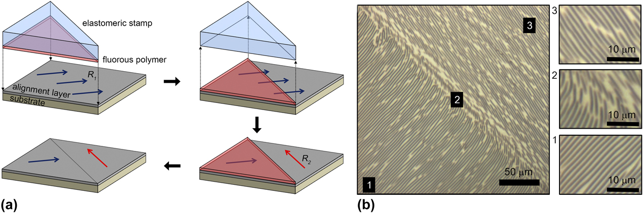
The SAR technique for achieving bidirectional alignment was illustrated in Fig. 4(a). A mold prepared for the desired pattern was coated with a film to be transferred. In our case, a fluorinated polymer thin-film was dip-coated on a predefined PDMS stamp. The PDMS is well known to be very hydrophobic, and thus most of the solutions can hardly be coated without any surface treatment. However, the fluorinated polymer solution of EGC-1700 (3 M Novec) can be clearly coated on a hydrophobic surface with uniformity due to the use of a highly volatile fluorous-solvent of HFE-7100 (3 M Novec). The solvent rapidly evaporated before the solution slips down from the surface of the PDMS mold, leaving the fluorinated polymer molecules on it, and the uniform thin film of the protective layer can consequently be formed. Then, the mold was brought into contact with a substrate to transfer a fluorinated polymer film (EGC-1700) from a mold to a substrate. Without any need to apply heat or pressure, intimate contact between the fluorinated polymer thin film and the substrate is produced when the stamp was placed on a substrate. When the mold was peeled-off, the fluorous polymer film on the protruding parts of the mold was transferred to the substrate. In terms of interfacial force, for this transfer to take place, the work of adhesion at the mold–polymer interface has to be smaller than that at the polymer–substrate interface.Reference Wang, Zhang, Xing, Yuan, Yan and Han43,Reference Wu44
Bi-directional wrinkles: (a) SAR technique for achieving the bi-directional alignment of the LCP layer having an alignment layer, which the rubbing directions are perpendicular to each other. (b) Microscopic images of the bidirectional wrinkles: (1) the initial alignment region, (3) the second alignment region, and (2) the region of the domain boundary.
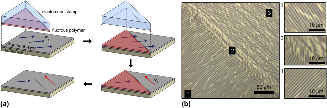
Now, we will introduce the new fabrication procedure of multi-directional wrinkled layers based on the stamping assisted rubbing (SAR) technique. The SAR technique for achieving bidirectional alignment is illustrated in Fig. 4. The alignment layer of PVA was spin-coated on a substrate and then rubbed unidirectionally to promote homogeneous alignment. Then, a protective layer on a patterned stamping mold of PDMS was transferred onto the first rubbed PVA by stamping and was cured at room temperature to cover the alignment layer partially. The secondary rubbing process was then performed perpendicular to the first rubbing direction.
When the second rubbing process was carried out on the entire substrate as well as the first rubbing, an uncovered region defined new orientation as later rubbing, but the region covered by the protective layer maintains the first orientation properties. After finishing secondary rubbing, the protective layer was dissolved in the HFE solvent of HFE-7100 to remove the patterned protective layer on alignment, and bidirectional alignment was readily achieved. Then, two-domain wrinkles induced on the bidirectionally aligned layer with the plasma treatment as the same as above.
Figure 4(b) shows the microscopic images of the LCP layer with a spatially separated wrinkled domain by using the SAR technique. Region 1 of Fig. 4(b) observed unidirectional wrinkles along the initial rubbing direction of R 1. On the other hand, wrinkles on the uncovered region (3) with the protective layer reconfigured along the second rubbing direction of R 2 due to the more dominant rubbing. Note that the intermediate region (2) seems to coexist both wrinkles of (1) and (3) and/or diagonal wrinkles between them. We assume that when wrinkles propagating in different directions meet each other, surface instability forms the boundary and is expected to form irregular wrinkles such as discontinuity or dislocation to have the most stable and low free energy state.
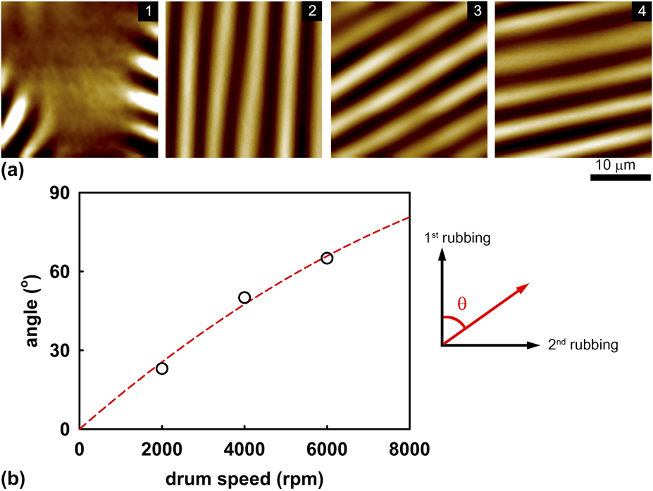
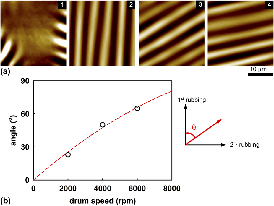
To verify the reconfiguration of wrinkling by secondary rubbing, a series of in situ studies were performed under AFM. Figure 5(a) shows the AFM images of the wrinkled LCP layer on the homogeneous alignment layer and each AFM image (from left to right) has a condition with different alignment conditions such as (1) un-rubbed and second rubbing of (2) 2000 rpm, (3) 4000 rpm, and (4) 6000 rpm. Note that each sample of (2)–(4) performed a first rubbing of 2000 rpm first. As mentioned before, uniform wrinkles appeared in the homogeneously rubbed alignment layer. However, the wrinkle would change when another rubbing (perpendicular to the first rubbing) was subsequently applied to the first rubbed alignment layer, the final released wrinkle pattern would change which affected dominantly by the latest rubbing configuration. Since the initial rubbing condition cannot be ignored, the direction of the wrinkle was observed itself from 0° to ∼90° with respect to the second rubbing condition as shown in Fig. 5(b). These phenomena were already observed in a liquid crystal cell, and Fuh and co-workers mentioned that the LC molecules tend to align in the direction of final rubbing, but first rubbing cannot be ignored.Reference Huang, Lin, Wang, Huang, Tsai and Fuh36 From this result, it was found that alignment properties such as the rubbing direction and strength were dominant factors to define the direction of wrinkles as in Fig. 5(b).
Influence of the additional rubbing condition on the first rubbed substrate: AFM images of (a) the homogeneous alignment layer of different rubbing conditiond including (1) no rubbing, (2) first 2000 rpm + second 2000 rpm, (3) first 2000 rpm + second 4000 rpm, and (4) first 2000 rpm + second 6000 rpm. (b) The angle of wrinkles changes which as a function of second rubbing.
C. Alternative wrinkling patterns
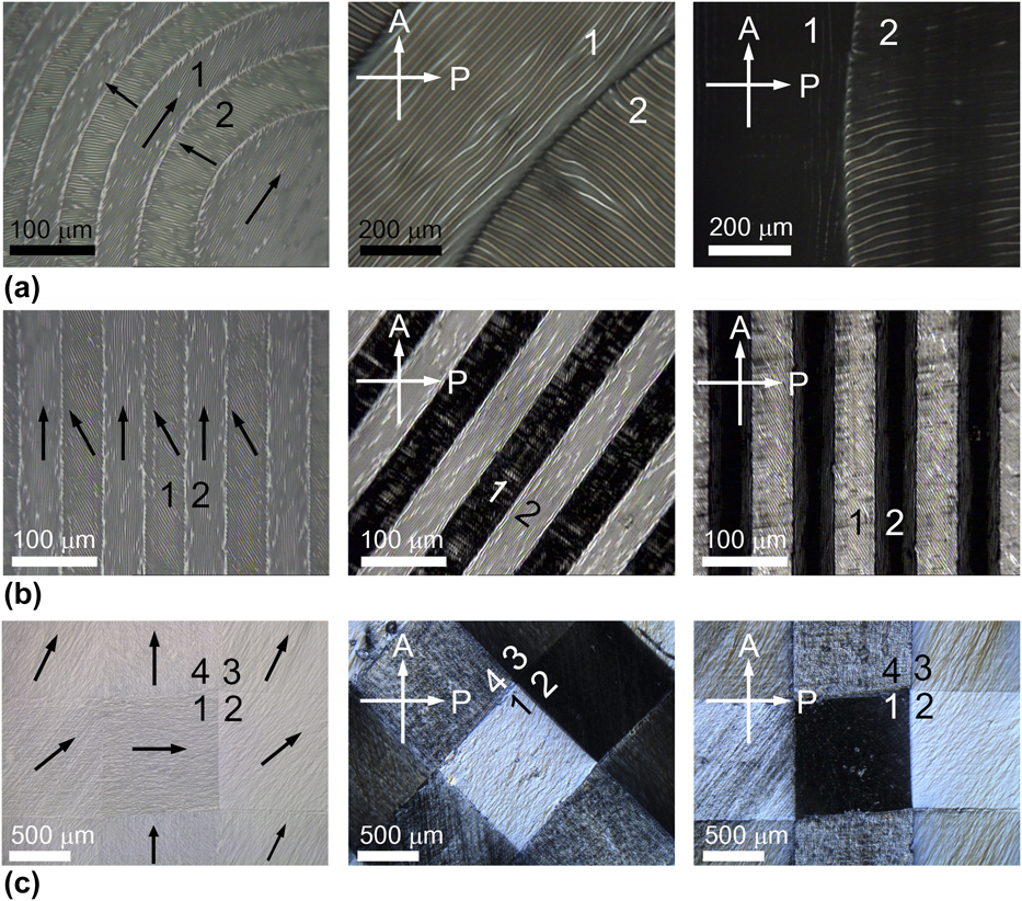
Based on surface wrinkling and alignment mixing phenomena, we have performed sophisticated patterns having poly-domain wrinkling. Further insight into the structural evolution of these wrinkled films was provided by optical microscope imaging with a crossed polarizer (DM750P, Leica) as shown in Fig. 6.
Alternative wrinkles: (a) orthogonal wrinkle divided into the concentric boundary, (b) line-by-line pattern of 45° difference, and (c) four-domain wrinkle having 0, 45, 60, and 90° with respect to the x-axis. Here, the initial thickness of the LC monomer was 700 nm-thick and the black arrows and numbers depict the rubbing direction on the alignment layer and each domain, respectively.
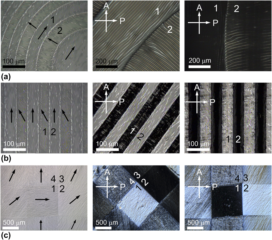
In the case of Fig. 6(a) having an orthogonal wrinkle divided into the concentric boundary, each domain has a uniform wrinkle structure and a clear boundary between domains. Here, black arrows depicted the rubbing direction on the PVA layer and the rubbing obtained perpendicular to each adjacent domain. As shown in polarizing microscopic images, it was found that the LC moieties, as well as the wrinkles, were aligned uniformly within each domain, despite the curved interfaces between adjacent domains. Another line-by-line separated sample having 45° rubbing angle difference between domains is shown in Fig. 6(b), and a well-ordered wrinkling structure is found on the surface. Since the adjacent domain defined alignment as 45° difference, phase retardation of LC occurred such as black domain (parallel or perpendicular aligned to the polarizer) and white domain (45° aligned to the polarizer). It could be applied to applications requiring optical effects as well as surface structures.Reference Kim, Na and Lee45,Reference Kim, Suh, Lee, Kim and Lee46
As mentioned above, our surface wrinkling method can be used to achieve multiple domains with different orientations, when the SAR technique is used iteratively. Figure 6(c) shows the alternating domain wrinkling surface having three different rubbing directions. We had used SAR repeatedly three times, and the first, second, and third rubbing processes were 1000, 3000, and 6000 rpm in speed, respectively. Note that the subsequent rubbing process should be stronger than the initial rubbing due to overcoming initial alignment properties. Every single domain defined unique wrinkling configuration and it could be clearly observed a different optical phase retardation between domains through a polarizing microscope as shown in Fig. 6(c). Our SAR and plasma treatment can easily achieve surface instability having a multi-directional ordering, but further research is required to minimize the undefined parts occurring at domain boundaries and to achieve uniform wrinkles.
IV. CONCLUSIONS
We have described a new approach to define highly ordered wrinkling morphologies based on a selective rubbing method from a LCP. The spontaneous pattern formation of periodic wrinkling morphology was achieved through utilizing plasma treatment on the predefined alignment layer. The multi-directional rubbing resulted in a spatially separated poly-domain alignment layer achieved through selectively covering the layer onto the alignment layer and it keeps alignment properties during the second rubbing process. The proposed method enables the spontaneous pattern formation of well-aligned one- or two-dimensionally periodic microstructures over a large area, without an additional template or patterning steps. In addition, this wrinkling formation in the thin film suggests a new strategy for micro-structuring with spontaneous wrinkling for applications in optoelectronics, photonics, and sensors.
Supplementary Material
To view supplementary material for this article, please visit https://doi.org/10.1557/jmr.2018.360.
ACKNOWLEDGMENTS
This work was supported by the research fund of Chungnam National University. J-H. Na thanks Hyperflex for supply rubbing cloths.