I. INTRODUCTION
The nuclear energy developments not only seek for the high efficiency of energy production, but also consider for the safe disposal of nuclear waste. Accelerator driven systems have been carried out widely because it has the possibility to transmute minor actinides and long lived fission products in nuclear spent fuel, that is, to realize the recycling of nuclear waste. Reference Kurata, Futakawa, Kikuchi, Saito and Osugi1 The spallation target is the lead-bismuth eutectic (LBE), which requires the structural materials to have excellent irradiation resistance and good compatibility with LBE. Reference Zhang and Li2 Therefore, low activation elements such as tungsten, vanadium, and tantalum have been added to replace the high activation ones such as molybdenum, niobium, and nickel, Reference Kohyama, Hishinuma, Gelles, Klueh, Dietz and Ehrlich3 which exhibit excellent irradiation resistance, Reference Jia and Dai4 good Pb–Bi corrosion resistance Reference Zhang5 as well as good mechanical strength Reference Gorse, Auger, Vogt, Serre, Weisenburger, Gessi, Agostini, Fazio, Hojna, Di Gabriele, Van Den Bosch, Coen, Almazouzi and Serrano6 such as high temperature strength and high temperature creep property. Reference Vanaja, Laha, Mythili, Chandravathi, Saroja and Mathew7 Reduced activation ferritic/martensitic (RAFM) steel is one of the candidate blanket structural material suited for nuclear fusion reactors because of a low coefficient of thermal expansion and excellent heat conductivity. Reference Kim, Yoon, Park and Kohyama8 The corresponding materials include the JLF-1, F82H, Eurofer97, CLAM, SIMP, and 9Cr2WVTa steel. Reference Yan, Liu, Bao, Weng and Liu9 The Institute of Metal Research, Chinese Academy of Sciences (IMR, CAS) has optimized the composition of 9Cr2WVTa steel and the toughness of base metal can reach 182 J at room temperature. Reference Wang, Lu, Dong, Li and Rong10,Reference Wang, Lu, Rong and Li11 For the structural materials, welding is indispensable for the production of nuclear fusion reactors. Gas tungsten arc welding (GTAW) is one of the high quality welding method and widely used in the complicated structure of all position welding. High quality weld metals can be obtained with the GTAW process because the electrode does not melt and welding heat input and filler addition can be controlled independently. Reference Chen, Yuan, Madigan and Xue12 Unfortunately, seldom reports could be found in terms of corresponding welding consumables. Therefore, it is necessary to exploit the indigenously developed welding consumables, which promotes the application for the Generation-IV nuclear power structural materials.
Toughness is an important consideration during hydro testing of components fabricated using 9 wt% Cr heat resistance steels. Reference Pai, Sogalad, Albert, Kumar, Mitra and Basavarajappa13 One of the methods for improving the toughness is to adjust the welding parameters. In a multi-layer and multi-pass welding, the weld metal microstructure is considerably modified as further layers are deposited on the top and on either side of a pass. Reference Mythili, Paul, Saroja, Vijayalakshmi and Raghunathan14 Many number of weld layers with reduced thickness of each weld layer may reduce the heat input which in turn improve the toughness of welds. Reference Pai, Sogalad, Albert, Kumar, Mitra and Basavarajappa13 The other method for improving the toughness is to optimize the alloying elements in the welding wire. Titanium is an economically attractive alloying element and is considered to improve the toughness and high temperature creep strength for 9 wt% Cr heat resistance steels. The movement of dislocations is obstructed by fine dispersion of titanium carbides and therefore, causing a significant improvement in creep strength. Reference Taneike, Fujitsuna and Abe15 Titanium addition reduces the austenite grain size and the martensite lath size, and moderate Ti (<0.018 wt%) content reduces the size of precipitated phase in 9CrWVTiN steel, which improves the toughness. Reference Zhang, Yu, Zhou, Liu, Fang, Li and Suo16 However, it is known that excessive titanium content can impart brittleness, and the use of titanium as a stabilizer typically emphasizes a titanium content as low as possible. Reference Jablonski, Alman, Dogan, Holcomb and Cowen17 Kim Reference Kim, Yoon, Park and Kohyama8 reported that a 0.028 wt% content of titanium was added in the JLF-1 welding wire. However, the effect of titanium on the mechanical properties, especially for the impact toughness on the 9 wt% Cr deposited metal is scarcely reported, therefore, it is necessary to investigate the role of titanium on the deposited metal for 9 wt% Cr heat resistance steel.
Welds with matching filler metals should be post weld heat treated (PWHT) to obtain temper martensite. PWHT at 760 ± 10 °C for 2 h is considered to relieve the welding stress and to get homogeneous tempered martensite structure. The lath structures have broken up and the sub-grains have formed during the PWHT process. Reference Arivazhagan, Prabhu, Albert, Kamaraj and Sundaresan18 A large number of precipitates, including the MX and M23C6 carbides, form in 9 wt% Cr steels after PWHT. MX are fine (10–50 nm) precipitates enriched in V, Ta, Ti, and C, which forms along martensite lath boundaries and inside lath as well. M23C6 is a coarse (100–200 nm) carbide enriched in Cr, W, and C and nucleates on martensite lath boundaries pinning grain boundaries. Reference Zhang, Melfi and Narayanan19
In this research, four filler metals with titanium content ranging from 0 to 0.15 wt% have been self-developed and fabricated by the IMR, CAS. The typical microstructures of weld metal have been analyzed and the microstructural evolution under welding thermal cycle have been researched. The distribution and size of Ti-enriched carbides have been characterized by the secondary ion mass spectroscopy (SIMS) and the high angle annular dark field-scanning transmission electron microscopy (HAADF-STEM). This study is aimed at investigating the effects of minor elements titanium on the microstructure and mechanical properties of multi-layer and multi-pass weldments with the alloy 9Cr2WVTa steel.
II. EXPERIMENTAL MATERIALS AND METHODS
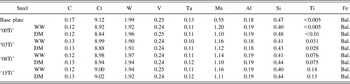
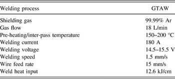
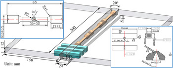
Four types of filler metals were fabricated with different titanium contents. The four filler metal chemical compositions were listed in Table I. Previous works showed that the 9Cr2WVTa filler metals with 0.12 wt% carbon content and 1.2 wt% manganese content exhibits good mechanical properties. Reference Wang, Rong, Li and Lu20 The base metal was 9Cr2WVTa steel, 300 × 120 × 12 mm in size. A single V groove at 10° on both sides was generated in a butt joint. The butt welding was performed using semi-automatic GTAW with the four filler metals wire that were 1.0 mm in diameter. The inert gas was argon. The welding parameters were listed in Table II. Approximately 27 weld passes in 8 layers in a flat position were filled for each weld. 100% radiographic inspection testing was used to detect the welding defects. Each welding wire welded two pieces of plate, one of them used as as-welded (AW) condition and the other one used as PWHT (760 °C/2 h) condition. The 9Cr2WVTa weldment with the depositing filler metal was investigated. Chemical analysis was performed using an ICP spectrometer and SIMS. The chemical compositions of the four deposited metals were listed in Table I and referred as ‘00Ti’, ‘03Ti’, ‘08Ti’, and ‘15Ti’, respectively. The microstructures of the weld metal obtained by etching with Viella’s reagent (1 g piric, 5 mL hydrochloric acid, and 100 mL ethanol) prior to imaging. An optical microscope (OM; Axio Lab.A1, Carl Zeiss Inc., Jena, Germany), scanning electron microscope (SEM; Inspect F50, FEI Company, Hillsboro, Oregon), electron backscatter diffraction (EBSD; Zeiss Supra 55, Carl Zeiss Inc.), and transmission electron microscope (TEM; Tecnai F20, FEI Company) were used to observe the macro-/micro-structures, the distribution and the size of precipitates and the crystal orientation. The schematic diagram of mechanical specimens taken from the weld deposited plate was shown in Fig. 1. The tensile and impact specimen sizes were designed in Fig. 1 as illustrations. The Charpy V impact tests and tensile tests were carried out on ZBC2452-C (SANS Co. Ltd, Shenzhen, China) instrument impact testing machine and AG-X 250 KN (Shimadzu Corp., Kyoto, Japan) tensile testing machine, respectively.
Chemical compositions for 9Cr2WVTa base plate, welding wires and deposited metals/wt%.

*WW: welding wire, DM: deposited metal.
Welding process parameters for 9Cr2WVTa steels.

Schematic diagram of tensile and impact specimens taken from the deposited metal plate.

III. RESULTS
A. Macro-/micro-structure of the deposited metal
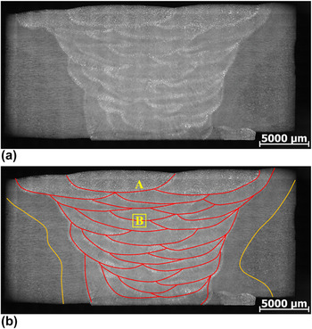
Figure 2 shows the macrographs on cross section of the typical ‘00Ti’ deposited metal. The top weld layer is the primary macro-structure that solidifies directly without undergoing the subsequent weld heating. The middle and bottom portions represent the macro-structure subjected to weld heating multiple times. Zone A and B marked in Fig. 2(b) represent the above two typical regions.
Macrographs on cross section of the typical ‘00Ti’ sample without (a) and with (b) edited.

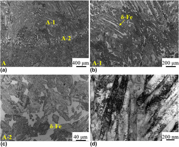
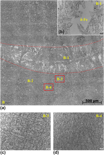
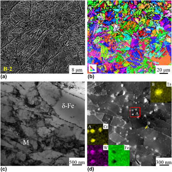
The micro-structure of Zone A is shown in Fig. 3(a). The microstructure consists of columnar martensite, with the average lath size of 150–250 nm. The corresponding TEM images are shown in Fig. 3(d). A mass of dislocations tangle around the martensite lath. The δ-ferrite is seen as a film distributed along the martensite lath, as shown in Fig. 3(b). Also, there exhibits the blocky ones in the fusion line (Zone A-2), as shown in Fig. 3(c). The micro-structure of Zone B is shown in Fig. 4. Zone B represents the macro-structure subjected to welding thermal cycle process multiple times. It is clearly seen that columnar grains are broken up, and equiaxed substructures are formed. In the area of weld interlayer, there also exists large number of δ-ferrite, as shown in Fig. 4(b). Volume fraction of δ-ferrite in the weld interface is found to be higher than those in other positions. At such high temperature located in δ + γ phase area, the driving force for the growth of δ-ferrite is high enough so that the δ-ferrite may grow rapidly with all directions and exhibit the polygonal one. Figure 5(a) shows the micro-structures of Zone B-2 in Fig. 4. The microstructures contain martensite with fine stripe δ-ferrite and exhibit uniform in the whole area. The fine stripe δ-ferrite decorated around the prior austenite grain boundary refines the grain sizes and makes the grain refinement and uniform. The crystal orientation map (standard IPF Z coloring) from the weld region shows that the grains exhibit the random orientation, as shown in Fig. 5(b). The random orientation indicates that the equiaxed grains have formed in replace of the columnar ones. Figure 5(c) shows the TEM image of martensite with δ-ferrite in the Zone B-2, the presences of a number of precipitates decorate the phase boundaries, lath boundaries as well as within the grains. Figure 5(d) shows the HAADF images of martensite in Zone B-2, the martensite laths have broken up and the sub-grains have formed. The coarse globular carbides with 100–200 nm in size distribute at the triple point of prior austenite grain boundaries and martensite laths, energy dispersive spectrum (EDS) result shows that the carbides are rich in Cr and W, as shown in illustration A in Fig. 5(d). The W existence is supposed to suppress the coarsening of M23C6 carbides. Reference Chauhan, Litvinov, de Carlan and Aktaa21 Also, there are large amount of Ta-enriched carbides in the intra-lath, with diameters between 20 and 80 nm, as shown in illustration B in Fig. 5(d). Figure 4(c) exhibits the martensite along with the equiaxed fine stripe δ-ferrite [Zone B-3 in Fig. 4(a)] while Fig. 4(d) exhibits the martensite along with the elongated fine stripe δ-ferrite [Zone B-4 in Fig. 4(a)]. By observing the relative position in detail, the Zone B-3 is closer to the next weld than the Zone B-4, that is, the Zone B-3 subjected to a higher peak temperature of welding thermal cycle than the Zone B-4. When the peak temperature of welding thermal cycle enters into the complete austenitizing region, the original structures transform into the γ phase, then the columnar structure has been replaced by the equiaxed one. As a consequence, the Zone B-3 exhibits the equiaxed structure while the Zone B-4 retains the original one. The δ-ferrite precipitates along the grain boundary as network and makes the grain refinement, as shown in Fig. 4(c). In the Zone B-4, the peak temperature of welding thermal cycle does not reach the austenite region and retains the original columnar structure, therefore, the δ-ferrite presents the elongated and decorates along the martensite lath, as shown in Fig. 4(d).
Micro-structures for the top of the deposited metal [Zone A in Fig. 2(b)]: (a) OM image; (b) OM image in Zone A-1; (c) OM image in Zone A-2 and (d) TEM image showing martensite along with high density dislocations.

Micro-structures for the middle of the deposited metal [Zone B in Fig. 2(b)]: (a) OM image; (b) OM image in Zone B-1; (c) OM image in Zone B-3 and (d) OM image in Zone B-4.

Micro-structures of Zone B-2 in Fig. 4(a): (a) SEM image showing martensite along with stripe like δ-ferrite; (b) crystal orientation map (standard IPF Z coloring) from Zone B-2 showing random orientation; (c) TEM image showing precipitations along with the interface of martensite and δ-ferrite and (d) HAADF image showing precipitates in the martensite.

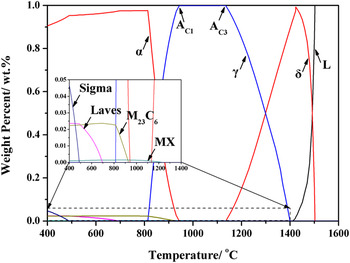
The solidified microstructure from the liquid pool directly is shown as: M + δ′. Where M is the untempered martensite transformed from the liquid pool and δ′ is the residual δ-ferrite. At this moment, the δ-ferrite exhibits the polygonal one. For the multi-layer and multi-pass welding, the microstructures are complex owing to the microstructures not only solidify directly from the liquid pool but also undergo the subsequent weld heating multiple times. The microstructural evolutions are dependent on the subsequent peak temperature of welding thermal cycle process. The microstructures after experiencing the different welding thermal cycle processes can be divided into three types, including the columnar crystal structure along with the polygonal δ-ferrite [Zone B-1 in Fig. 4(b)], the lath structure broken along with the equiaxed δ-ferrite [Zone B-3 in Fig. 4(c)] and the original lath structure retained along with the elongated δ-ferrite [Zone B-4 in Fig. 4(d)]. For the Zone B-1, when the peak temperature of welding thermal cycle process is close to the liquidus temperature, for example, in the range between 1400 and 1500 °C, as shown in Fig. 6 calculated by the Thermo-Calc software with TCFE7 database. The above phase transformation process can be written as follows:
 $${\rm{M}} + \delta ' \to {\rm{L}} + \delta \to {{\rm{M}}_1} + \delta '\quad ,$$
where M1 is the martensite transformed from the liquid phase and δ phase during the quick cooling from the high temperature near the melting zone. The peak temperature of welding thermal cycle process falls into the L + δ region, where the δ-ferrite retains to the room temperature partially and exhibits the polygonal one.
Content of phase as function of temperature in 9Cr2WVTa deposited metals.

The Zone B-3 and Zone B-4 are the main parts in the whole deposited metal. The δ-ferrite morphology change in the central weld is due to additional heat treatments produced by further weld passes. When the deposited metal experiencing the multiple welding thermal cycle processes, M23C6 carbides with 100–200 nm in diameter precipitate along the grain boundaries and MX carbides with 20–80 nm in size are found within the grain, as shown in Fig. 5(d). The number and the size of precipitations are visible. The residual δ-ferrite is still present, as shown in Fig. 5(a). The δ-ferrite morphology change in the center of the sample is due to additional heat treatments produced by further weld passes. Further passes modify the microstructure to more fine and stable one. The microstructures are almost uniform but with a little difference. There exist differences in martensite morphology owing to the slight difference in welding thermal cycle process. When the peak temperature of the subsequent welding thermal cycle process drops into the complete austenite region, the columnar grains tend to breakup, and the equiaxed substructures develop gradually. The δ′ partial transforms to the γ phase and the phase transformation process can be written as follows:
 $${\rm{M}} + \delta ' \to \gamma + \delta ' + {{\rm{M}}_{23}}{{\rm{C}}_6} + {\rm{MX}} \to {{\rm{M}}_2} + \delta ' + {{\rm{M}}_{23}}{{\rm{C}}_6} + {\rm{MX}}\quad {\rm{,}}$$
where M2 is the quenched martensite transformed from the γ phase during the cooling process. M23C6 and MX are the carbide precipitates. In the same way, when the peak temperature of the subsequent welding thermal cycle process is lower than the AC1 point, that is, the peak temperature of welding thermal cycle process enters into the partial austenite (α + γ) region, the columnar grains retains and the region is equivalent to a tempering treatment. The phase transformation process can be written as follows:
 $${\rm{M}} + \delta ' \to \alpha + \gamma + \delta ' + {{\rm{M}}_{23}}{{\rm{C}}_6} + {\rm{MX}} \to {{\rm{M}}_2} + {{\rm{M}}_3} + \delta ' + {{\rm{M}}_{23}}{{\rm{C}}_6} + {\rm{MX}}\quad {\rm{,}}$$
where M3 is the over-tempered martensite transformed from the α phase during the cooling process.
B. Micro-structures and mechanical properties of the deposited metals with different titanium contents
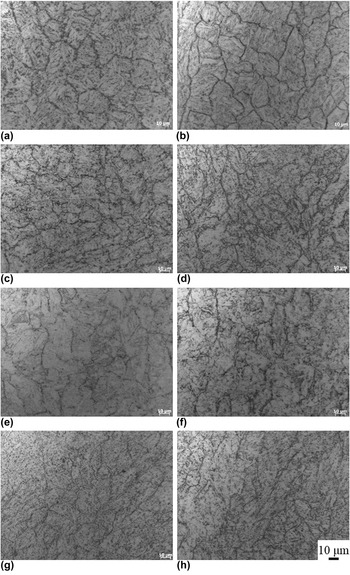
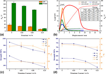
Figure 7 shows OM images for the 9Cr2WVTa deposited metals with different titanium contents in the AW condition and after PWHT. All the photographs are taken from the central weld (Zone B-2 in Fig. 4), which represent for the typical microstructures in the whole deposited metal. All the samples consist of martensite and fine stripe δ-ferrite, which exhibit no significant difference between each other. Figure 8(a) shows the toughness of 9Cr2WVTa deposited metals with different titanium contents. The toughness for the ‘00Ti’ sample in the AW condition is 37.2 J, and decreases with the titanium content increasing. For the ‘15Ti’ sample in the AW condition, the toughness obtains the lowest and is only 11.7 J. When the samples experiencing the PWHT process, the toughness are 166.7, 149.9, and 127.1 J for the ‘00Ti’, ‘03Ti’, and ‘08Ti’ samples, respectively. The toughness for the samples after PWHT improves significantly comparing with the samples in the AW condition. Also, the toughness for the deposited metal after PWHT matches well with that for the base metal. However, the toughness is only 15.2 J for the ‘15Ti’ sample after PWHT, 3.5 J higher than the ‘15Ti’ sample in the AW condition, but much lower than the other samples after PWHT. Figure 8(b) shows the load(energy)–deflection curves of the instrumented impacts for the ‘03Ti’ and ‘15Ti’ samples in the AW condition and after PWHT. The Charpy impact specimens typically experience five different stages of fracture: elastic deformation, plastic deformation, ductile propagation, brittle propagation, and ductile fracture, denoted W1, W2, W3, W4, and W5, respectively. Reference Lan, Qiu, Zhao, Gao and Du22 The fracture process consists of crack initiation and crack propagation process. The crack initiates only when the load is higher than the maximum load (P m), indicating that there is no crack during the elastic and plastic deformation process. Thus, elastic and plastic deformation stages represent the crack initiation stage, and the sum of corresponding absorbed energies is regarded as the crack initiation energy (W1 + W2). Similarly, the sum of relevant absorbed energies in the subsequent three stages of fracture is considered as the crack propagation energy (W3 + W4 + W5). Reference Zhao, Hu, Wang, Kang, Yuan, Di and Misra23 The maximum loads in the impact of the ‘03Ti’ samples in the AW condition and after PWHT are 18.2 and 20.6 kN, whereas the impact toughness are 27.9 and 151.9 J, respectively. The elastic deformation energy for the above two samples are 7.79 and 8.53 J, while the plastic deformation energy are 3.69 and 50.13 J, the ductile propagation energy are 4.42 and 69.31 J, respectively. Therefore, the ‘03Ti’ sample after PWHT have better resistance for the deformation and crack propagation than the sample in the AW condition, that is, the ‘03Ti’ sample after PWHT shows higher toughness and reaches to 151.9 J. Comparing the load(energy)–deflection curves of ‘15Ti’ samples in the AW condition and after PWHT, the toughness has no obvious change while the maximum load increases from 5.4 to 9.0 kN, as shown in Fig. 8(b).
OM images for the 9Cr2WVTa deposited metals with different titanium contents: (a) ‘00Ti’, AW; (b) ‘00Ti’, PWHT; (c) ‘03Ti’, AW; (d) ‘03Ti’, PWHT; (e) ‘08Ti’, AW; (f) ‘08Ti’, PWHT; (g) ‘15Ti’, AW; (h) ‘15Ti’, PWHT.

(a) Impact tests for the 9Cr2WVTa deposited metals in the AW condition and after PWHT with different titanium contents; (b) the load(energy)–deflection curves of the instrumented impacts for the 9Cr2WVTa deposited metals; tensile tests for the 9Cr2WVTa deposited metals with different titanium contents (c) in the AW condition and (d) after PWHT.

Figures 8(c) and 8(d) show the tensile results for the 9Cr2WVTa deposited metals with different titanium contents. When the titanium content is no more than 0.08 wt%, both the yield strengths and the tensile strengths decrease with the titanium content increasing. However, the elongation and the reduction of area remain almost constant. The maximum tensile strength is 948 MPa for the ‘00Ti’ sample in the AW condition, much higher than that for the base metal (717 MPa). Reference Wang, Lu, Rong and Li11 When the sample experiencing the PWHT, the tensile strength decreases to 742 MPa and is close to that of the base metal. The yield ratios are about 75% both for the samples in the AW condition and after PWHT. The elongations for the 9Cr2WVTa deposited metals in the AW condition are about 18% while 21% for the samples after PWHT. Also, the reductions of area for the 9Cr2WVTa deposited metals in the AW condition are about 60% while 70% for the samples after PWHT. However, when the titanium content increases to 0.15 wt%, All the tensile properties decrease, especially for the yield strength and the tensile strength.
The yield strength, tensile strength, and toughness for the 9Cr2WVTa base metal are 566 MPa, 717 MPa, and 182 J, respectively. Reference Wang, Lu, Dong, Li and Rong10,Reference Wang, Lu, Rong and Li11 The above-mentioned mechanical properties for the 9Cr2WVTa deposited metal can be set as no less than 550 MPa, 700 MPa, and 120 J, respectively. To make the weld joint mechanical properties matching the properties of the base metal, the titanium content should no more than 0.08 wt% in the 9Cr2WVTa deposited metal.
IV. DISCUSSION
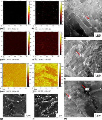
As mentioned before, with the titanium content increasing, the mechanical properties for the deposited metal become poor, especially for the ‘15Ti’ samples. Therefore, the role of titanium on microstructures and mechanical properties for the deposited metal should be researched thoroughly. To investigate the minor elements (titanium) distribution in the deposited metal, SIMS is a well-established technique for obtaining chemical information from the sample and the limit of detection can reach the ppm level. Figure 9 shows the SIMS images of the deposited metal with ‘03Ti’ and ‘15Ti’ samples. The Ti-enriched carbides almost distribute along the martensite lath, by the way, the V-enriched carbides exist at the same position with the Ti-enriched carbides. The amount of Ti-enriched carbides in the ‘15Ti’ sample is much more than those in the ‘03Ti’ sample, also the size of Ti-enriched carbides in the deposited metal increases from 200 nm to 1 μm, as shown in Figs. 9(g) and 9(h). Figures 9(i)–9(k) show the HAADF images for the 9Cr2WVTa deposited metals with different titanium contents. The carbides are rich in Ti, V, and Ta and can be written as (Ti, Ta, V)C. Ti strongly interferes with the precipitation of (Ta, V)C. TiC hardly exists in the matrix alone and therefore, it acts as the core of (Ti, Ta, V)C particle. Reference Zhang, Yu, Zhou, Liu, Fang, Li and Suo16 The carbides precipitate from the high temperature and grow up quickly, from 100 nm to 1 μm in diameter. Moreover, the shapes of carbides turn from the rod-shaped into the blocky ones, as shown in Fig. 9(i)–9(k).
SIMS images [(e) and (f)] showing the distribution of titanium [(a) and (b)] and vanadium [(c) and (d)]; SEM images [(g) and (h)] showing the distribution and the size of precipitates with ‘03Ti’ [(a), (c), (e) and (g)] and ‘15Ti’ [(b), (d), (f), and (h)] samples in the AW condition, HAADF images for the 9Cr2WVTa deposited metals after PWHT with different titanium contents: (i) ‘03Ti’; (j) ‘08Ti’ and (k) ‘15Ti’.

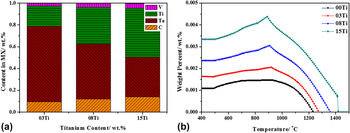
Figure 10(a) shows the alloy compositions for the MX carbides. With the increase of titanium content, the titanium content in the MX carbides increases from 18 wt% to 45 wt%, while the tantalum content in the MX carbides decreases from 69 wt% to 36 wt%. Therefore, the MX carbides transform from (Ta, Ti, V)C carbides to (Ti, Ta, V)C carbides with the titanium content increasing. Figure 10(a) shows precipitated amount of MX carbides in the 9Cr2WVTa deposited metals with different titanium contents calculated by the Thermo-Calc software. The precipitation temperatures of MX carbides are 1230 °C, 1270 °C, 1360 °C, and 1420 °C for the ‘00Ti’, ‘03Ti’, ‘08Ti’, and ‘15Ti’ samples, separately. In the meantime, the liquidus temperature is 1400 °C for the 9Cr2WVTa steel (Fig. 6). The (Ti, Ta, V)C carbides in the ‘15Ti’ sample are the primary precipitated phase and therefore, grow and coarsening significantly.
(a) Constituent elements in the MX carbides and (b) precipitated amount of MX carbides in the 9Cr2WVTa deposited metals with different titanium contents calculated by the Thermo-Calc software.

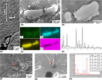
The coarse primary precipitated phase may have some influence on the mechanical properties. By observing the longitudinal sections of impact samples in detail, the blocky carbides fracture and the cracking direction is parallel to the load direction, as shown in Fig. 11(a). EDS mapping results show that the blocky ones are rich in C, Ta, and Ti but depleted in Fe, therefore, the carbides are (Ti, Ta, V)C. When the sample experiencing the PWHT, the blocky (Ti, Ta, V)C carbides still fracture under the impact load, as shown in Figs. 11(d) and 11(e). Figures 11(f) and 11(g) show the impact fractographies for the ‘15Ti’ sample in the AW condition. The river lines indicate that it is initiated by the micro-crack formed by the (Ti, Ta, V)C particles, as shown in Fig. 11(f). There exhibit the cleavage facets on the fracture surface, the blocky (Ti, Ta, V)C carbides act as the crack initiation site during the impact process [Fig. 11(g)], which makes the maximum loads (5.4 and 9.0 kN) much lower than those with fine carbides (18.2 and 20.6 kN), as shown in Fig. 8(b). Relevant literature Reference Ye, Wang, Li, Zhang and Li24 reported that the crack would propagate into the matrix and result in a cleavage fracture as the radius of particles is over 0.6 μm. In this study, the size of (Ti, Ta, V)C carbides are about 1 μm in diameter when the titanium content is as high as 0.15 wt%, as shown in Fig. 11(h). In summary, the blocky (Ti, Ta, V)C carbides are the main factor effecting the impact toughness.
The fractured blocky Ti-enriched particles for the ‘15Ti’ samples after the impact test: (a) and (b) the fractured blocky Ti-enriched particles; (c) EDS mapping of the fractured blocky Ti-enriched particles for the sample in the AW condition; (d) the fractured blocky Ti-enriched particles and (e) EDS spectrum of the fractured blocky Ti-enriched particles for the sample after PWHT; the impact fractographies for the ‘15Ti’ sample: (f) and (g) the crack initiation zone and (h) EDS spectrum of the crack initiation site in (f) and (g) with the red arrow.

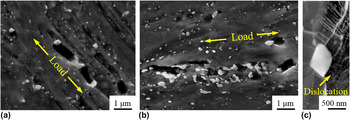
For the ‘15Ti’ sample, the cracks initiate at the interface between the matrix and the blocky (Ti, Ta, V)C particles after the tensile test, as shown in Fig. 12(a) and 12(b). The voids are formed at the interface of elongated coarse interlath carbides, and void consolidation leads to fractures. The deformations between martensite and blocky (Ti, Ta, V)C particles are inconsistent during the tensile process, therefore, the interface is the weak site and easy to crack under the tensile load. In summary, the blocky (Ti, Ta, V)C particles are the main factor affecting the tensile properties.
Longitudinal section for the ‘15Ti’ samples (a) in the AW condition and (b) after PWHT after tensile test and (c) HAADF image around Ti-enriched carbides.

The mechanical properties for the martensite steel are dependent on the particle cracking, including the precipitates, inclusions, and second phases. Reference Curry and Knott25 During the particle cracking, the fracture initiation sites are determined by the microstructural variables such as the size, volume fraction, morphology, and spatial distribution of the particles. Reference Li, Xiao, Li, Zhang, Luo and Zhang26 The Ti-enriched carbides can pin up a lot of dislocations around the particles, as shown in Fig. 12(c). It is reported that the dislocations pile-up at a grain/carbide interface can cleave the grain boundary carbides and thus initiate the microcrack. Reference Curry and Knott27 As mentioned above, the cracks initiate at the carbides inside and the carbide–matrix interface in the tensile/impact process. According to the fracture model of grain boundary carbides proposed by Smith, Reference Curry and Knott25,Reference Curry and Knott27 the larger sizes of grain boundary carbides bring to the lower critical fracture stress of a carbide–matrix interface. Therefore, the higher titanium content in the 9Cr2WVTa deposited metal can result in the sharp deterioration of impact toughness, and even the brittle fracture (Charpy impact energy < 15 J).
V. CONCLUSIONS
The typical microstructures and the mechanical properties for the 9Cr2WVTa deposited metals have been investigated and analyzed. The effects of precipitations on the mechanical properties have been discussed. The following conclusions can be drawn from this study:
-
(1) The typical microstructures for the 9Cr2WVTa deposited metals are comprised of the martensite and the δ-ferrite. The surface layer exhibits the columnar structure and the δ-ferrite is seen as a film distributed along the martensite lath. The microstructures are uniform in the middle of the weld pool and exhibit the equiaxed structure. The δ-ferrite presents the fine stripe and decorates along the prior austenite grain boundaries and therefore, refines the grain size.
-
(2) The Ti-enriched carbides increase from 200 nm to 1 μm in diameter with the titanium content increasing. The cracks initiate at the carbides internal and the carbide/matrix interface under the load when the titanium content is 0.15 wt%. The primary blocky Ti-enriched particles are the main factor affecting the mechanical properties for the 9Cr2WVTa deposited metal.
-
(3) The 9Cr2WVTa deposited metals obtain good mechanical properties when the titanium content does not exceed 0.08 wt%.
ACKNOWLEDGMENTS
This work was supported by the National Natural Science Foundation of China (No. 91226204) and the Chinese Academy of Sciences Strategic Pilot Project (The future of advanced nuclear energy-ADS evolution system) under Grant No.: XDA03010304. The authors acknowledge the valuable discussions with Mrs. Min Tong in IMR, CAS.