1. Introduction
Legged robots are in point-to-point contact with the ground. So, compared with traditional tire-type, crawler-type, and other mobile robots, legged robots have better adaptability to complex ground environments. Therefore, legged robots have become a research hotspot. In recent years, some teams have achieved remarkable results, such as Boston Dynamics’s legged robots [Reference Raibert, Blankespoor, Nelson and Playter1], the HYQ series of quadruped robots of the Italian Research Institute [Reference Semini, Barasuol, Goldsmith, Frigerio, Focchi, Gao and Caldwell2–Reference Barasuol, Villarreal Magaña, Sangiah, Frigerio, Baker, Morgan, Medrano-Cerda, Caldwell and Semini5], and the quadruped robots of the Massachusetts Institute of Technology [Reference Wensing, Wang, Seok, Otten, Lang and Kim6–Reference Carlo, Wensing, Katz, Bledt and Kim11]. Electric actuators [Reference Wensing, Wang, Seok, Otten, Lang and Kim6–Reference Carlo, Wensing, Katz, Bledt and Kim11] and hydraulic actuators [Reference Raibert, Blankespoor, Nelson and Playter1–Reference Barasuol, Villarreal Magaña, Sangiah, Frigerio, Baker, Morgan, Medrano-Cerda, Caldwell and Semini5] are the most widely used by legged robots, and hydraulic actuators have obvious advantages over electric actuators in high-speed and high-load legged robots, such as their size, weight, and force-to-weight ratio. However, hydraulic actuators still face three problems that cannot be avoided in legged robots.
For legged robots such as bipedal robots, quadruped robots, and others undergoing high-speed jump-running, foot-to-ground impacts are caused by the feet touching the ground, especially during longer flight phases such as exemplified by springboks, which are typical jump-running quadruped animals. Assuming no springs and dampers mechanism is installed, and no buffer algorithm is applied to the leg–foot system, the robot’s leg–foot stiffness is very large due to the actuators’ response lags and the structure of the leg–foot system. In this case, the robot system is thrown onto the ground like a rigid block with a vertical downward velocity.
At the moment of collision, there is a large impact force,
 ${F_i}$
, between the foot and the ground, which imparts a large impact force to the leg–foot mechanism and other parts in the robot. This requires us to design parts with sufficient strength that can withstand such impact forces. The weight of the robot will increase via the inclusion of additional applied materials, which has an adverse effect on its running speed and jumping height. In addition, the impact force,
 ${F_i}$
, quickly spreads to the robot body along the leg–foot mechanism, which can cause vibrations and even instabilities in the body, as shown in Fig. 2. As a result, we must design a complex algorithm that considers impact forces to maintain the stability of the robot. The impact force,
 ${F_i}$
, can be described by Eq. (1):
 \begin{equation}{F_i} = \frac{{{m_t}g}}{4} + \frac{{{m_t}{V_f}}}{{\Delta t}},{V_f} = \sqrt {2gh} \end{equation}
where
 ${m_t}$
is the total mass of the robot system,
 ${V_f}$
is the vertical velocity of the robot’s foot,
 $\Delta t$
is the impact duration,
 $h$
is the jump height, and
 $g$
is the acceleration due to gravity.
Solving for
 ${F_i}$
is one of the key problems that we must pay attention to. If we do not solve the
 ${\rm{\;}}{F_i}$
problem, any designed legged robot will be at risk of running unstably, and even breaking. In addition, most designers artificially limit the jumping height of their legged robot to avoid excessive values of
 ${\rm{\;}}{F_i}$
, which is an important reason why robots do not jump very high. At present, solutions to account for the impact force buffer mainly include the installation of elastic elements, such as elastic bones [Reference Ananthanarayanan, Azadi and Kim9], a flexible spine [Reference Folkertsma, Kim and Stramigioli12], elastic drivers [Reference Pratt and Krupp13,Reference Sharbafi and Seyfarth14], and springs [Reference Raibert, Blankespoor, Nelson and Playter15–Reference Liu and Ben-Tzvi17]. Elastic elements can quickly respond to an impact to achieve fast buffering, and such elements can also convert part of the impact energy into elastic potential energy which is then stored. This stored elastic potential energy can then be released spontaneously to assist the robot’s forward-jumping. However, elastic elements are passive, and hence, not controllable. More importantly, the parameters of elastic elements change with time, which have adverse effects on the design of the control algorithm. Additionally, if elastic elements are used in robots employed in harsh environments, their service lifetimes tend to be shorter.
Another design solution for impact force buffers is to design buffer algorithms to control the leg–foot mechanism to achieve an active buffer, such as hybrid position/force control [Reference Raibert and Craig18], dynamic force/torque control [19], and stiffness and impedance control [Reference Mehdi and Boubaker20]. The advantage of buffer algorithms is that all components in the system are controllable. However, their main disadvantage is high energy consumption during the control process, as designed buffer algorithms applied in robot systems need to consume energy to achieve the desired buffer movement. It is also difficult to design a proper buffer algorithm to adapt to a complex robot system with changeable parameters.
The second problem with which we are concerned is that hydraulic actuators need to output instantaneous high power to achieve forward-jumping. However, hydraulic actuators do not always work under high-load conditions. Indeed, it is a contradiction that the hydraulic actuators must be designed according to the maximum output power to meet the robot’s normal motion. Thus, there can be power waste when the hydraulic actuators are employed under low-load conditions, resulting in an increase in energy consumption. In addition, the weight of the hydraulic actuators increases the total weight of the robot; thus, controlling the overall weight of the robot, a compact and lightweight design is necessary. However, the problem caused by such a compact and lightweight design is that the hydraulic actuators installed in the robot system may not be able to provide sufficient power to support jump-running.
The current solutions to this problem include high- and low-pressure oil source switching [Reference Yunfeng, Lei, Ruina, Lingdong, Chenxing, Peng, Qichang, Qindan, Liang, Zhenjie and Yuchuan21]. At least two hydraulic pumps with different output pressures are installed in the robot system, and at least two servo valves are used to switch between the different input pressures of the actuators. Although the problem of different output powers of the actuators has already been solved [Reference Yunfeng, Lei, Ruina, Lingdong, Chenxing, Peng, Qichang, Qindan, Liang, Zhenjie and Yuchuan21], high- and low-pressure oil source switching will impact the hydraulic circuit and easily produce the water hammer effect, which will impart negative effects to the hydraulic system. Multiple hydraulic pumps in the system also increase the amount of energy consumption, although they do not output work pressure at the same time. Finally, the weight of the robot increases due to the inclusion of these hydraulic pumps.
The third problem is that hydraulic actuators need to recover the impact energy (if it is not recovered, it will become thermal energy and disappear) and reuse it in the robot’s motion to increase the endurance of legged robots. Some hydraulic actuator systems have been proposed to realize the recovery and reuse of impact energy, such as hydraulic serial elastic actuators [Reference Blickhan, Seyfarth, Geyer, Grimmer, Wagner and Gunther22], hydraulic servo actuators with passive compliance [Reference Kim, Lee, Shin, Lee, Park and Ahn23], and hydraulic energy-recovery systems [Reference Chu, Luo and Fu24]. Although the proposed hydraulic actuator systems solve the problems of impact buffering and impact energy recovery and reuse, it is still unfortunate that the problem of switching between high load and low load in these systems has not yet been solved.
As mentioned above, there are many contradictions in robotic designs, and it is a challenge to balance the overall performance of a legged robot, especially in jump-running. To solve these contradictions, we here propose using a new bionic hydraulic actuator system, inspired by the springbok movement.
2. Springbok movement process
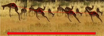
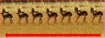
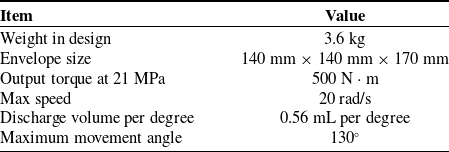
A springbok, which is a typical quadruped animal, has a unique way of running and jump-running, as shown in Fig. 1. A springbok can run at high speeds, and the height of its center of gravity changes significantly. In other words, springboks have a relatively long flight phase, that is, the springbok can produce a short, explosive muscle power output when its foot touches the ground to obtain a high forward and upward speed. It can maintain this high forward speed as it propels itself through the air, instead of using a swinging leg–foot; thus, the frequency of impact is reduced. Additionally, a springbok’s muscles may be fully relaxed during this flying phase, which allows it to store enough energy to buffer the impact and jump forward again. Overall, a springbok can spend less energy than a cheetah to maintain its high forward speed, which is an important reason why it can run at high speeds for longer durations than predatory animals. The springbok’s manner of achieving jump-running not only produces high forward speeds but also high jumps, which is why we chose the springbok as a template for our bionic design. Table I shows some of the parameters we expect in our design, which are similar to the key parameters of the springbok.
Some key parameters we expect in our bionic design.

A springbok is a typical jump-running quadruped animal. An adult springbok can jump to heights of 3.5 m and distances of 15 m. The springbok moves from right to left as shown by the arrow.

As a basis for designing our bionic legged robot, and the subsequent hydraulic joint actuator system, we analyzed the cyclic movement process of the springbok and divided it into four processes: standing, forward-jump, take-off, and buffer.
2.1. Standing process
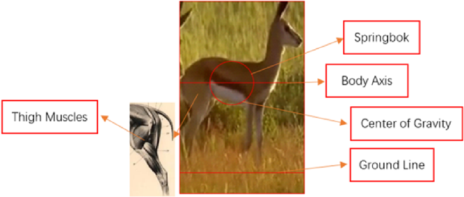
During the standing process, all four of the springbok’s feet are in contact with the ground. The springbok’s body axis is almost parallel to the ground line, and its leg–foot system only bears its weight. Hence, its leg–foot muscles’ output power is very small. Figure 2 shows the standing position.
Standing process: all four feet are in contact with the ground, and the axis of the springbok’s body is almost parallel to the ground line.

2.2. Forward-jump process
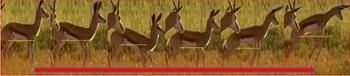
During the forward-jump process, the springbok’s leg–foot system first curls up so that its leg–foot muscles and leg–foot bones form an appropriate angle combination. Powerful thigh muscles pull the thigh bones to the back of the springbok’s body, a coordinated movement with calf extension, which gives the springbok the ability to achieve large vertical upward and horizontal forward speeds, as shown in Fig. 3. In this process, the springbok’s leg–foot muscles need to output an explosive force that pushes its body upward and forward in a short time, and the movement power is extremely high.
Forward-jump process. The yellow line is parallel to the ground, and the red lines show the relative positional change of the springbok’s body–leg–foot system. The legs of the springbok curl up to a certain extent. Then, the hind feet provide a support point, and a forward-jump is realized under the drive of its thigh muscles. The center of gravity gradually rises during this process. The springbok moves from left to right as shown by the arrow.

2.3. Take-off process
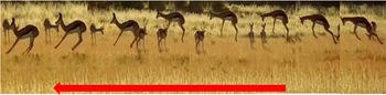
During the take-off process, the springbok’s feet leave the ground, and its body flies in the air due to inertia, as shown in Fig. 4. The springbok’s flying process follows the momentum theorem. If air resistance is not considered, the forward speed of the springbok will not decay, and the forward velocity during this process will be the same as the initial velocity produced when its feet leave the ground. The springbok will adjust the positions of its thighs and calves relative to its body during the take-off process to provide good support and buffer angle for the feet to touch the ground. Since the springbok obtains a great vertical upward speed after the forward-jump, it flies through the air for a long time, which is conducive to the long-lasting maintenance of the speed in the forward direction. This process also provides sufficient time for additional adjustments in the position of its leg–foot system to allow its muscles to recharge. During this process, the movement power is small.
Take-off process. The main movement feature is adjusting the relative position of the springbok’s body–leg–foot system. Movement of the center of gravity is similar to a parabola with an initial velocity. The springbok moves from right to left as shown by the arrow.

2.4. Buffer process
During the buffer process, there is an instantaneous impact when the foot touches the ground. At the end of the take-off process, the springbok has already adjusted its leg–foot system into a suitable position to buffer this instantaneous impact force. After the impact, the springbok’s leg–foot system curls up to further buffer the movement caused by the vertical speed of its body and reduce speed loss in the forward direction, as shown in Fig. 5. The buffer process will not end until the springbok’s body sinks to a position where the vertical velocity is buffered to zero. The downward vertical speed of the foot becomes zero at the moment the foot contacts the ground, and the impact is transmitted along its leg–foot system to its body. For its body, the lost downward vertical velocity imparts another impact on its leg–foot system. Finally, the force that its leg–foot system needs to bear is several times greater than the springbok’s body weight. In other words, its leg–foot muscles need to output enough power to maintain its leg–foot buffer position.
Buffer process. The relative position of its body–leg–foot system is adjusted to buffer the impact. After the impact, the springbok’s body continues to sink to reduce the vertical velocity to zero. The springbok moves from right to left as shown by the arrow.

2.5. Some analysis conclusions
Based on the above analysis, the basic movement requirements of the springbok’s leg–foot system are as follows.
-
1. First, the leg–foot muscles of the springbok must have sufficient explosive power to complete the forward-jump and bear the impact force. As such, they need to have very strong leg–foot muscles, as shown in Fig. 5.
-
2. Second, its leg–foot system must have sufficient strength and flexibility to bear and buffer the impact force. The springbok’s leg–foot system, which is composed of elastic muscles and bones, satisfies the above requirements.
Based on the principle of bionics, the designed quadruped robot will have similar structures as possessed by the springbok. To be more specific, the joint driver system installed in the leg–foot system of the quadruped robot will have the characteristics of sufficient explosive power, sufficient strength, flexibility, high frequency response, low energy consumption, and low weight.
3. New bionic hydraulic joint actuator system
In the previous section, we made some conclusions regarding what desirable properties the joint actuator system should possess: the joint actuator system of the quadruped robot should have sufficient explosive power, sufficient structure strength, sufficient flexibility, high frequency response, low energy consumption, and low weight. Based on these conclusions, we established the robot’s design concept on impact buffering, impact energy absorption, impact energy storage, and force bursts. It is worth noting that the concepts of impact energy absorption, impact energy storage, and force bursts are proposed for the hydraulic actuator system of robots.
-
1. Impact buffer: the concept that the leg–foot system can realize an impact buffer.
-
2. Impact energy absorption: the concept that the leg–foot system can absorb the energy caused by any impacts, which will become heat and disappear if not absorbed.
-
3. Impact energy storage: the concept that the absorbed impact energy can be stored.
-
4. Force burst: the concept that the joint driver system can be controlled to output more force.
The concept of impact energy absorption and impact energy storage can reduce energy consumption, which can improve the endurance of the robot. These concepts are explored further in the following sections.
Main structure of the new bionic hydraulic joint actuator system.

3.1. Composition of the new bionic hydraulic joint actuator system
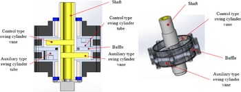
The new bionic hydraulic joint actuator system is mainly composed of a double-layer single-vane hydraulic swing cylinder, hydraulic accumulator, pressure-reducing valve, high-speed two-position four-way solenoid directional valve, servo valve, check valve, pressure sensor, and valve block. Figure 6 is a schematic diagram of the 3D model of the new bionic hydraulic joint actuator system. The main specifications of the new bionic hydraulic joint actuator system are shown in Table II.
Main specifications of the new bionic hydraulic joint actuator system.

To reduce the robot’s weight, we replaced the normal two single-vane hydraulic swing cylinders with a double-layer single-vane hydraulic swing cylinder, as shown in Fig. 7. The first layer of the single-vane hydraulic swing cylinder is defined as a control-type swing cylinder, and the second layer is defined as an auxiliary type swing cylinder. Also, the two chambers in the auxiliary type swing cylinder are separated by vanes, one of which is defined as a buffer chamber, and the other is defined as a force burst chamber.
Double-layer single-vane hydraulic swing cylinder.

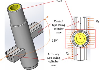
Pressure acting on the shaft in the red frame can be partly counteracted.

The vanes of the control-type swing cylinder and the auxiliary type swing cylinder are arranged at an interval of 180°, as shown in Fig. 8, which allows their output forces to partly counteract the force of the hydraulic pressure acting on the shaft. The force,
 ${F_{shaft}}$
, acting on the shaft can be described as Eq. (2), which allowed us to design a thinner shaft to reduce the weight:
 \begin{equation}{F_{shaft}} = {P_C}A - {P_A}A\end{equation}
where
 ${P_C}$
is the pressure of the control-type swing cylinder acting on the shaft,
 ${P_A}$
is the pressure in the auxiliary-type swing cylinder acting on the shaft, and
 $A$
is the projected area of the shaft in which the pressure acts.
In the design, we also use a combination of carbon-fiber material (i.e., the black and yellow parts in Fig. 9 and the black parts in Fig. 8) and an aluminum alloy (i.e., all other parts in Figs. 8 and 9) to meet the requirements of high strength and low weight. Finally, we achieve very high power density through these original weight reduction designs, as shown in Table III.
Comparison of different actuators.

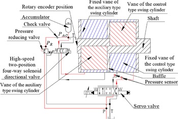
Hydraulic circuit diagram of the new bionic hydraulic actuator system.

3.2. Working principle
Servo valve ports A and B are connected to the control-type swing cylinder. One side of the port consists of a high-speed two-position four-way solenoid directional valve connected to the auxiliary type swing cylinder, while the other side is connected with the oil tank and the accumulator. A high-pressure oil source is connected to the accumulator port through the pressure-reducing valve and check valve, as shown in Fig. 9.
The new bionic hydraulic joint actuator system was installed as the thigh movement source based on the fact that the thigh muscles of animals are stronger than the other muscles in the leg–foot system. The working principle is explained in detail in the following sections based on the basic movement of the springbok.
3.2.1. Take-off and standing processes
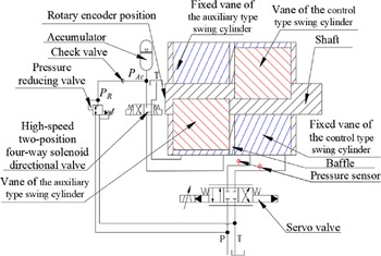
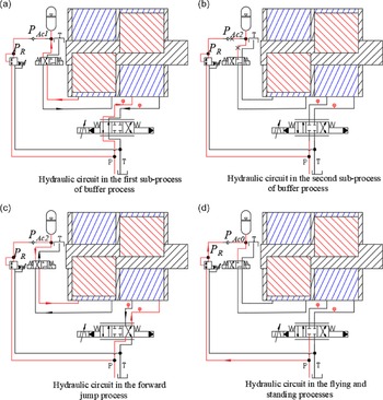
The new bionic hydraulic actuator is in a low-load condition during the take-off and standing processes, as mentioned above. The high-speed two-position four-way solenoid directional valve is at the right position. The inlet and outlet ports of the auxiliary swing cylinder are connected to the oil tank, while the two chambers of the auxiliary swing cylinder are both connected to the low-pressure oil source. In other words, the auxiliary swing cylinder vane can move freely. The control-type swing cylinder is controlled by the servo valve to generate the desired movement. The oil path from the accumulator to the auxiliary swing cylinder is cut off. At the same time, the high-pressure oil from the oil source can flow into the accumulator through the pressure-reducing valve, and then through the check valve, which restores the pressure of the accumulator to that set by the pressure-reducing valve. In this way, the accumulator has the same initial pressure when the impact energy is absorbed to eliminate the accumulation of errors caused by the different energy of each collision. The hydraulic circuit is shown in Fig. 10.
Hydraulic circuit during the take-off and standing processes. The red line is the high-pressure oil path, and the black line is the low-pressure oil path. If
 ${P_R} > {P_{Ac0}}$
, the hydraulic oil from the high-pressure hydraulic oil source will flow into the accumulator through the pressure-reducing valve and the check valve.

3.2.2. Buffer process
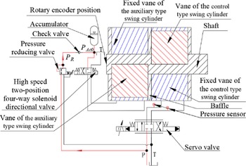
Here, the buffer process is subdivided into two subprocesses. The first is the momentary foot-touching process, and the second is a further buffer process controlled by the control-type swing cylinder. During the first subprocess, the high-speed two-position four-way solenoid directional valve is switched to the left position, as shown in Fig. 11. The switching trigger signal comes from a plantar force sensor or pressure sensors. Then, the buffer chamber of the auxiliary swing cylinder is connected to the accumulator, and the force burst chamber is connected to the oil tank. The impact force is transferred from the shaft to the vane of auxiliary swing cylinder, and the vane of auxiliary swing cylinder pushes the hydraulic oil in the buffer chamber into the accumulator. Thus, the auxiliary swing cylinder works like a pump. The hydraulic oil from the oil tank source fills the volume of the force burst chamber. A buffer force will then be produced by the elastic structure inside the accumulator, as shown in Fig. 12.
Hydraulic circuit during the first subprocess.

Main structure of the accumulator. The gas or spring in the accumulator can be compressed to buffer the oil impact caused by the foot–ground impact.

In addition, the pipe effect and the throttling effect of the high-speed two-position four-way solenoid directional valve will also produce some buffer force. Finally, the impact buffer is achieved by the above-mentioned structure. The buffer force,
 ${F_{f1}}$
, increases gradually because the pressure in the accumulator also rises gradually. We can adjust the initial pressure,
 ${P_{Ac0}}$
, of the accumulator to determine the softness of the leg–foot system at the moment when a foot touches the ground. In this way, the feet of the robot will not collide with the ground rigidly. The high-speed two-position four-way solenoid directional valve is in the left position until the impact force is less than the set value. Here, we will not discuss the detailed control strategy, which instead will be the subject of future papers.
Hydraulic oil is squeezed into the accumulator, which is driven by the impact. As the buffer process proceeds,
 ${P_{Ac1}}$
will gradually become greater than
 ${P_R}$
. At the start of the buffer process, the pressure in the accumulator is
 ${P_{Ac0}}$
, and the buffer torque,
 ${T_{f0}}$
, generated by the pressure in the accumulator can be described by Eq. (3) as:
 \begin{equation}{T_{f0}} = {L_e}{A_a}{P_{Ac0}}\end{equation}
where
 ${L_e}$
is the equivalent arm length of the leg–foot system, and
 ${A_a}$
is the equivalent action area. As the buffer process proceeds, the buffer torque,
 ${T_{f1}}$
, generated by the pressure in the accumulator can be described by Eq. (4):
 \begin{equation}{T_{f1}} = {L_e}{A_a}{P_{Ac1}}\end{equation}
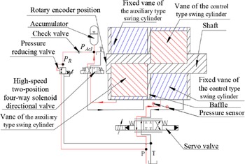
The first subprocess will end when the impact force is less than the set value. The second subprocess will then start at once. During the second subprocess, the leg–foot system curls further to buffer the vertical velocity of the body to zero. During this process, the high-speed two-position four-way solenoid directional valve is switched to the right position, as shown in Fig. 13. The control swing cylinder and the auxiliary swing cylinder then return to the working state mentioned in Section 3.2.1. However, there are some differences. For example, the hydraulic oil squeezed by the vane of the auxiliary swing cylinder into the accumulator has a higher pressure than the pressure set by the pressure-reducing value. In other words, impact energy is converted into pressure energy and stored in the accumulator. In addition, the higher pressure hydraulic oil in the accumulator cannot flow to the pressure-reducing valve due to the existence of the check valve. Moreover, as the outlet pressure of the pressure-reducing valve is greater than the set pressure, the oil source hydraulic oil cannot flow into the accumulator through the pressure-reducing valve and the check valve.
Hydraulic circuit during the second subprocess.

At the end of the first subprocess,
 ${P_{Ac1}}$
is already much greater than
 ${P_R}$
. Thus, the check valve cuts off the hydraulic circuit from the high-pressure oil source to the accumulator. The high-speed two-position four-way solenoid directional valve cuts off the oil circuit from the accumulator to the auxiliary type swing cylinder. The impact energy is converted to pressure energy,
 ${E_i}$
, which is stored in the accumulator.
 ${E_i}$
can be described by Eq. (5) as:
 \begin{equation}{E_i} = {K_a}\left( {{P_{Ac1}} - {P_{Ac0}}} \right)\end{equation}
where
 ${K_a}$
is the equivalent energy coefficient of the accumulator.
3.2.3. Forward-jump process
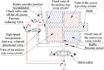
As mentioned in Section 2.5, the actuators of the leg–foot system need to output instantaneous explosive power during the forward-jump process. The high-speed two-position four-way solenoid directional valve is switched to the left position at the end of the second buffer subprocess. The buffer chamber of the auxiliary swing cylinder is connected to the accumulator again. The force burst chamber of the auxiliary swing cylinder is connected to the oil tank, as shown in Fig. 14. The high-pressure hydraulic oil in the accumulator flows into the buffer chamber of the auxiliary swing cylinder and then pushes the vane of the auxiliary swing cylinder to output additional torque to assist in realizing instantaneous explosive power output. Finally, the force burst is realized.
Hydraulic circuit of the forward-jump process.

The pressure in the accumulator changes from
 ${P_{Ac1}}$
to
 ${P_{Ac2}}$
during the forward-jump process. At the end of the forward-jump process, the pressure in the accumulator,
 $\;{P_{Ac2}}$
, is smaller than
 $\;{P_{Ac0}}$
, and the high-speed two-position four-way solenoid directional valve is switched to the right position. Then, the hydraulic oil flows from the high-pressure hydraulic oil source to the accumulator through the pressure-reducing valve, and then the check valve, to restore the accumulator. The accumulator gradually returns to the initial pressure set by the pressure-reducing valve to continue the next movement cycle.
We can see that the working process of the bionic hydraulic oil joint actuator system can match the movement process of a springbok well, which functions as a complete closed loop. At the start of the loop, the accumulator, the key element of the system, is always set to the same initial pressure state regardless of the influence of the unpredictable factors in the movement process, such as the different impact forces. Figure 15 summarizes how the working process of the bionic hydraulic joint actuator system relates to the movement process of the springbok.
Summary of the relationship between the movement process of the springbok and the working process of the new bionic hydraulic joint actuator system.

4. Simulations
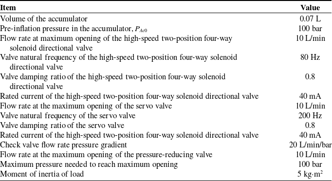
In this section, we perform simulations to verify the feasibility of the proposed system. As mentioned above, the function of the new bionic hydraulic actuator system is mainly reflected in the take-off process, buffer process, and forward-jump process. In the simulations, we assume that the quadruped robot falls from a height which is shown in Table IV, and then completes the buffer process and forward-jump process. The total buffer angle is about 60° and the forward-jump angle is about 110°. What we want is the final state, so we do not consider how the quadruped robot reaches the buffer angle and the forward jump angle. Here, we give a linear control signal to the servo valve.
Key parameters of the system components.

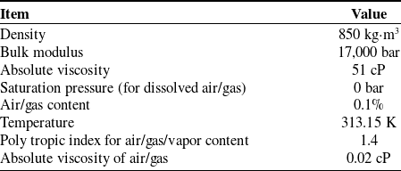
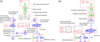
In the simulations, we consider the high-speed two-position four-way solenoid directional valve and servo valve as a second-order system. The dynamic performance parameters of these valves in the simulations were based on values of related products that have been widely used [Reference Barasuol, Villarreal Magaña, Sangiah, Frigerio, Baker, Morgan, Medrano-Cerda, Caldwell and Semini5]. Other key parameters are shown in Table IV. The parameters of the hydraulic oil in the simulation shown in Table V were used in the LMS AMESIM software.
Parameters of the hydraulic oil used in the LMS AMESIM simulations.

Simulation diagram in AMESIM. (a) The new bionic hydraulic joint actuator system and (b) the classical hydraulic joint actuator system.

We built the new bionic hydraulic joint actuator system shown in Fig. 16(a) and classical hydraulic joint actuator system shown in Fig. 16(b) using mature hydraulic components in AMESIM.
We assume that the new bionic hydraulic actuator system is installed on the robot, as mentioned by [Reference Lin, Chen, Ren, Huang, Chen and Fu26]. According to the foot-impact duration mentioned by [Reference Lin, Chen, Ren, Huang, Chen and Fu26], we use Eq. (6) to calculate the impact torque
 $T$
acting on the shaft, as shown in Fig. 20:
 \begin{equation}T = {F_i}{L_q}\end{equation}
where
 ${L_q}$
is the force produced by the moment arm,
 ${L_q} = 0.25{\rm{\;m}}$
.
The component’s parameters considered in the simulations mainly included the pressure in the accumulator, shaft torque, shaft displacement, and the high-speed two-position four-way solenoid directional valve control signal. Under the impact torque values shown in Fig. 20, the component parameters in the system as a function of time were determined, as shown in Fig. 17.
Impact torque applied in the simulations.

Results of the impact buffer.

Results of the impact energy absorption.

We decomposed the simulation into four parts to provide a detailed description according to the four concepts put forward in Section 3, as summarized in the following sections.
4.1. Concept of impact buffer
Under the action of the given impact torque, there is a short time lag after the high-speed two-position four-way solenoid directional valve is triggered by the set pressure sensor. The opening of the high-speed two-position four-way solenoid directional valve in the simulation was set to 100% of its maximum opening. As seen in Fig. 18, when the impact torque reaches a maximum value of 500 N/m, the actual output torque of the new bionic hydraulic joint actuator system is 257.43 N/m, which is mainly due to the action of the accumulator air spring. In other words, the value of the buffer torque is 242.6 N/m, and the buffer torque ratio reaches 48.52%. The actual output torque of classical hydraulic joint actuator system is 451.2 N/m, and the buffer torque ratio is 9.76%. Thus, the impact buffer of the new bionic hydraulic joint actuator system is significant, which shows that the new bionic hydraulic joint actuator system effectively implements the concept of an impact buffer.
4.2. Concept of impact energy absorption
The absorption of impact energy is achieved by an increase in the pressure in the accumulator, as shown in Fig. 19. The pressure in the accumulator increases from 99.92 bar to 188.45 bar, at a rise rate of 88.45%, that is, the impact energy gradually becomes hydraulic energy in the accumulator.
4.3. Concept of impact energy storage
The impact energy is finally partially converted into hydraulic energy in the accumulator. The hydraulic energy in the accumulator is stored for a short time with the right position function of the high-speed two-position four-way solenoid directional valve and the check valve function, as shown in Fig. 19. This process is essentially the second buffer subprocess. The purpose of this process is to provide time for the servo valve to make accurate adjustments so that the leg–foot system has the same position before starting each forward-jump process.
Results of the force burst.

4.4. Concept of force burst
The torque on the shaft of the new bionic hydraulic joint actuator system is as high as 898.2 N
 $\cdot$
m at the moment when the high-speed two-position four-way solenoid directional valve is opened. As the accumulator pressure continues to decrease, the torque on the shaft gradually decreases. At the end, the torque on the shaft is only about 100 N
 $\cdot$
m of static body weight under the condition of controlling the shaft at a constant speed, as shown in Fig. 20. The accumulator pressure drops from 188.45 bar to 87.8 bar. The torque on the shaft of the classical hydraulic joint actuator system is only 502.1 N
 $\cdot$
m, which is the maximum output torque of the classical hydraulic joint actuator system. The results show that the new bionic hydraulic joint actuator system achieves a burst of force.
The buffer angle of classical hydraulic joint actuator system is −61.56°, and the buffer angle of new bionic hydraulic joint actuator system is −58.9°. The forward-jump angle of the classical hydraulic joint actuator system and the new bionic hydraulic joint actuator system is +50°, as shown in Fig. 21. In the simulation of the classical hydraulic joint actuator system, the control signal of the servo valve intervenes at 0.1 s. In the simulation of the new bionic hydraulic joint actuator system, the control signal of the servo valve intervenes at 0.34 s. The circle in the diagram shows that the control-type swing cylinder controlled by the servo valve is activated by the auxiliary type swing cylinder, which results in a smaller control error than with the classical hydraulic joint actuator system.
Results of the shaft displacement and the control signal.

5. Conclusions
In the context of developing an efficient quadruped robot, we analyzed the movement process of a springbok and split it into four processes: standing, forward-jump, take-off, and buffer. Based on these, some key characteristics of actuators were summarized, such as sufficient explosive power, sufficient strength, flexibility, high frequency response, low energy consumption, and low weight. We established some key concepts for the proposed actuator system: impact buffering, impact energy absorption, impact energy storage, and force burst. Based on these, we proposed a new bionic hydraulic joint actuator system which consists of a double-layer single-vane hydraulic swing cylinder, hydraulic accumulator, pressure-reducing valve, high-speed two-position four-way solenoid directional valve, servo valve, check valve, pressure sensor, valve block, etc. The working principle was explained based on the movement process of a springbok. It was shown that the working process of the new bionic hydraulic joint actuator system can match the movement process of a springbok well.
The simulation results showed that the new bionic hydraulic joint actuator system realizes the functions of the established concepts. Compared with the classical hydraulic joint actuator system, the new bionic hydraulic joint actuator system can provide a better impact buffer and greater output force. More importantly, the new bionic hydraulic joint actuator system can convert impact energy into hydraulic energy stored in the accumulator and provide additional energy for the next movement, which enables the impact energy to be recovered and reused. The proposed actuator system has the potential to assist legged robots to achieve higher running speeds, higher jumping heights, longer endurance, heavier loads, and lighter mass.
In the future, we need to further study the mathematical model of the system to find the numerical relationships between the different components and the system. We will also study the mathematical relationship between the system control signals, system components, and the impact force of quadruped robots at different jumping heights, speeds, and gaits and design a prototype to experimentally verify the performance of the system.
Acknowledgements
We thank International Science Editing (http://www.internationalscienceediting.com) for editing this manuscript.
Conflicts of interest
We declare that we do not have any commercial or associative interest that represents a conflict of interest in connection with the work submitted.
Financial support
There is no financial support for this work.
Ethical considerations
This article does not contain any studies with human participants or animals performed by any of the authors. Informed consent was obtained from all individual participants included in the study.
Author contributions
Jiaqi Li contributed to the conception of the study, performed the data analyses, and wrote the manuscript; Dacheng Cong contributed significantly to analysis and manuscript preparation; and Yu Yang and Zhidong Yang helped perform the analysis with constructive discussions.