NOMENCLATURE
- Cp
static pressure coefficient
- R
transition radius between the fuselage surface and the fore diversion surface of the submerged inlet
- R1
 $\sim $R19
static pressure taps mounted on the ramp-side surface
- C1 $\sim $C11
static pressure taps mounted on the cowl-side surface
- D
diameter of the duct exit, mm
- DC 60
circumferential distortion descriptor
- M 0
freestream Mach number
- M AIP
mass-averaged Mach number at the duct exit
- $\overline {p_{AIP}^ * } $
mass-averaged total pressure at the AIP, Pa
- $\overline {p_{60,\min }^ * } $
minimum mass-averaged total pressure over any 60
$^{\circ}$ section at AIP, Pa- $\overline {{q_{AIP}}} $
mass-averaged dynamic pressure at the AIP, Pa
- x
axial distance, mm
- H c
height of the captured flow by the inlet


Greek Symbols
- $\alpha$
angle-of-attack(
$^{\circ}$)- $\beta$
yaw(
$^{\circ}$)- $\sigma$
total pressure recovery
- $\delta$
boundary-layer thickness
- $\alpha$f
diversion angle of fore lip
- $\alpha$a
diversion angle of aft lip
- $\beta$1
deflection angle at the starting station of the inner spline
- $\beta$2
deflection angle at the ending station of the inner spline
- $\beta$3
deflection angle at the starting station of the outer spline
- $\beta$4
deflection angle at the ending station of the outer spline


Subscripts
- 0
of freestream
- AIP
at the duct exit (the aerodynamics interface plane)
1.0 INTRODUCTION
A submerged inlet differs from the traditional pitot S-shaped inlet type and has many advantages: firstly, it eliminates the frontal-facing cavity and thus has excellent electromagnetic stealth performance(Reference Shi and Guo1); secondly, it can effectively reduce the windward area of aircraft and reduce drag; thirdly, it is easy to store, carry and launch because of its simple outer geometry and shape. However, because the entrance is completely mounted on the surface of the fuselage, a large amount of the forebody boundary layer is swallowed by the inlet, resulting in a deterioration of internal flow, which undoubtedly poses a great challenge to the aerodynamic design and practical engineering application of the submerged inlet.
Frick et al. first designed the National Advisory Committee for Aeronautics (NACA) submerged inlet in 1945(Reference Frick, Davis, Randall and Mossman2). However, because of its small captured mass flow and low total pressure recovery, it is employed only for auxiliary applications(Reference Seddon and Goldsmith3). With the evolution of design methodologies, submerged inlets have gradually been extended from auxiliary system applications to the main air intake system for propulsion engines. Guo and Liu proposed a Computer-Aided Design (CAD)-technique-based design method for the submerged inlets(Reference Guo and Liu4). Yu et al. revealed the air-admission mechanism for the submerged inlets on a planar surface using both numerical simulations and low-speed tunnel experimentation(Reference Yu5). Wang et al. proposed a design methodology for submerged inlet lip surface and demonstrated the effectiveness on complex parameterised geometries(Reference Wang, Wang, Xiao, Chen, Zhou, Guo and Sun6). Sun et al. designed and tested a submerged inlet with a trapezoid entrance, which has an excellent performance at the design condition and provides satisfactory performance over a wide range of test conditions(Reference Sun, Guo and Wu7). However, it is undeniable that the total pressure loss and circumferential distortion at the exit of the submerged inlet are worse than for the conventional S-shaped inlets. As a result, varieties of flow control technologies have been applied to improve the aerodynamic performance. For example, delta-wing vortex generators(Reference Prez, Ferreira, Da Silva, De Jesus and Oliveira9) and bump-shaped vortex generators(Reference Sun, Tan and Wang10) are applied on the upstream fuselage surface; side-edge vortex bleed(Reference Cheng, Tan, Sun and Tong11) is used at the entrance; and fin-type protrusions(Reference Taskinoglu and Knight12,Reference Jovanovic, Taskinoglu, Knight and Elliott13) are applied on the internal surfaces. Nevertheless, we still have an incomplete understanding of the effect that the forebody boundary layer has on the aerodynamic performance of a submerged inlet.
Based on the flow field of submerged inlets(Reference Sun and Guo14), the forebody boundary layer is expected to reduce the total pressure of the captured airflow. Furthermore, the swallowed boundary layer could further increase the losses in the internal diffuser. Therefore, it is important to evaluate the impact of the forebody boundary layer on the submerged inlet performance, with the goal of better flow control. In this paper, forebody boundary-layer low-energy flow was diverted away by a unique submerged diverter, which was positioned upstream of the entrance of the submerged inlet. The influence of the forebody boundary layer on the flow pattern and aerodynamic performance of the submerged inlet, with and without the unique diverter, was investigated by wind-tunnel experimentation and numerical simulations. Meanwhile, the main mechanisms for losses in the submerged inlet were also analysed.
Three-dimensional geometry of the submerged inlet model with a submerged diverter.

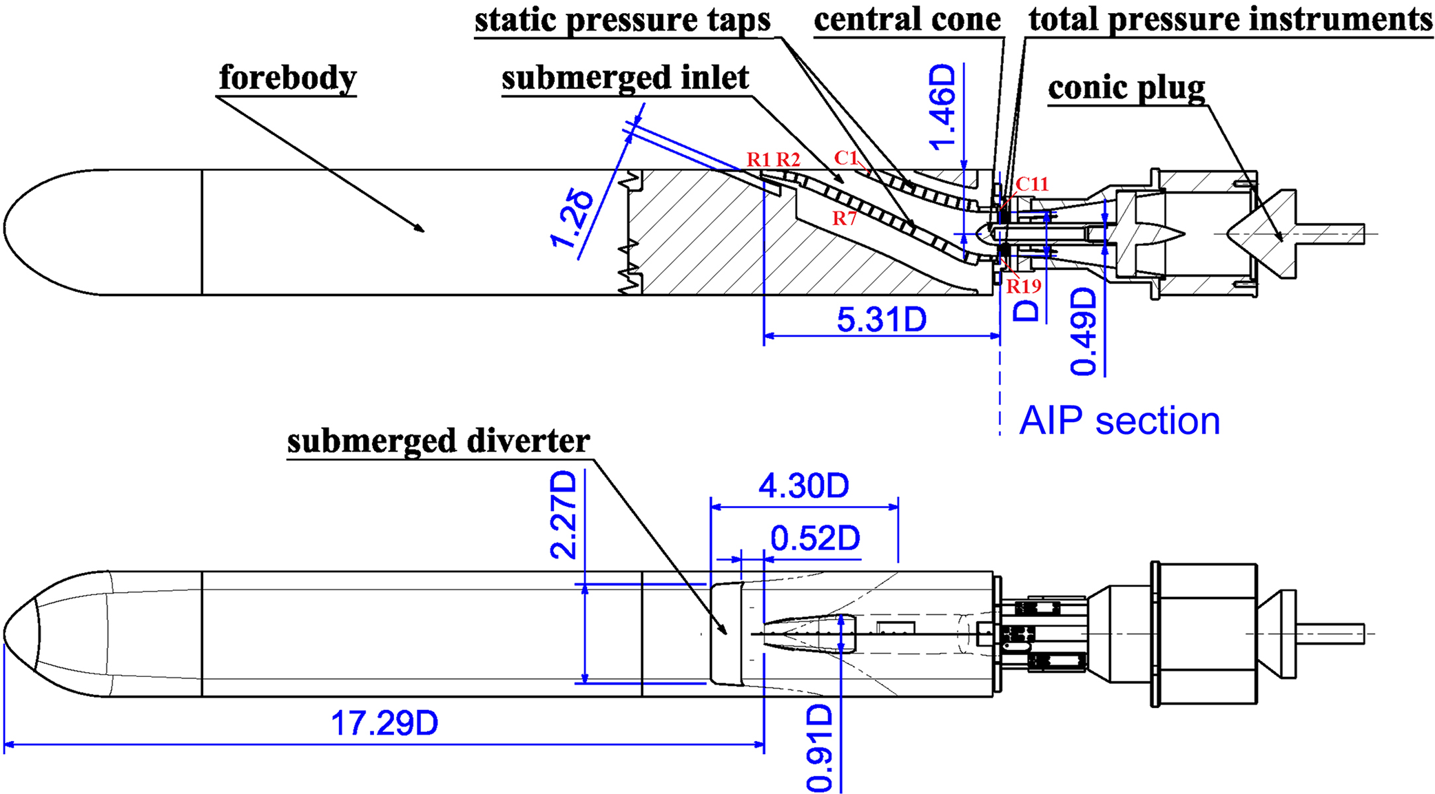
Sketch of the inlet model.

Sketch of the submerged diverter.

2.0 METHODOLOGY
2.1 Submerged inlet model
The three-dimensional geometry of the submerged inlet with the submerged diverter is displayed in Fig. 1. The cross-section of the aircraft fuselage is rectangular with rounded corners. The entrance of the submerged inlet has a trapezoid shape, and the key design parameters are shown in Fig. 2. The entrance of the submerged diverter is mounted upstream of the inlet fore lip. The internal flow path of the submerged diverter is divided into left and right passages, and each passage gradually deviates from the symmetrical plane. The forebody boundary layer is sucked into the diverter, and the exits are located on both sides of the fuselage (Fig. 3). As illustrated in Fig. 3, the diversion angle of fore lip ( $\alpha$f) is 23
 $^{\circ}$, and the diversion angle of aft lip (
 $\alpha$a) is 26
 $^{\circ}$. The transition radius R between the fore diversion surface and the fuselage surface is 1.2D, where D (45mm) is the exit diameter of the submerged inlet. The entrance height at the trailing edge station of the diverter is 1.2
 $\delta$ (
 $\delta$ is the Computational Fluid Dynamics (CFD) calculated boundary-layer thickness at the trailing edge station, under the conditions of M 0 = 0.6,
 $\alpha$ = 0
 $^{\circ}$,
 $\beta$ = 0
 $^{\circ}$ and without the diverter). The side edge angle of the entrance is 4
 $^{\circ}$. The diverter entrance is much wider than the submerged inlet entrance (Figs. 2 and 3) to reduce the amount of low-energy boundary-layer flow entering the inlet(Reference Sun, Guo and Wu7). The internal channel is gradually turned to the side of the fuselage following the Non-Uniform Rational B-Spline (NURBS) curves(Reference Piegl and Tiller8), and the cross section is rectangular. From the top view, the deflection angles at the starting and ending stations of the inner spline (
 $\beta$1 and
 $\beta$2) are 17.4
 $^{\circ}$ and 34.9
 $^{\circ}$, respectively, and the deflection angles at the starting and ending stations of the outer spline (
 $\beta$3 and
 $\beta$4) are 3.7
 $^{\circ}$ and 17.8
 $^{\circ}$, respectively. From the side view, both lower and upper splines are horizontal at the ending stations. While the internal channel contracts in the spanwise direction and expands in the vertical direction, the area of the cross section remains nearly unchanged.
Apart from reducing the low-energy boundary-layer flow, the tested submerged diverter imposes little effect on the mainstream flow upstream of the inlet entrance. This ensures the same upstream mainstream flow conditions, with and without the submerged diverter. Therefore, the impacts to the forebody boundary-layer low-energy flow can be examined. If traditional diverters were employed, the entrance plane of the inlet would inevitably be extended beyond the fuselage. This would increase the windward area and affect the mainstream flow passing the inlet entrance, especially under the conditions of high angle-of-attack and sideslip of the freestream. In this study, a replaceable cover was used to achieve the switch between the inlet with or without the diverter.
2.2 Experimental setup
To examine the effects of the forebody boundary layer on the flow pattern and aerodynamic performance of the submerged inlet, experiments were carried out using the NH-1 wind tunnel at Nanjing University of Aeronautics and Astronautics(Reference Sun, Guo and Wu7). The test section of the tunnel is 600mm × 600mm square. During the experiment, the test range of the free-stream Mach number varied from 0.3 to 0.6, and the ranges of the angle-of-attack and yaw of the test model were –6 ∼ 8 $^{\circ}$ and 0 ∼ 4
 $^{\circ}$, respectively. The detailed test conditions are presented in Table 1.
Test conditions

Submerged inlet test model; (a) baseline inlet; (b) inlet with a submerged diverter.

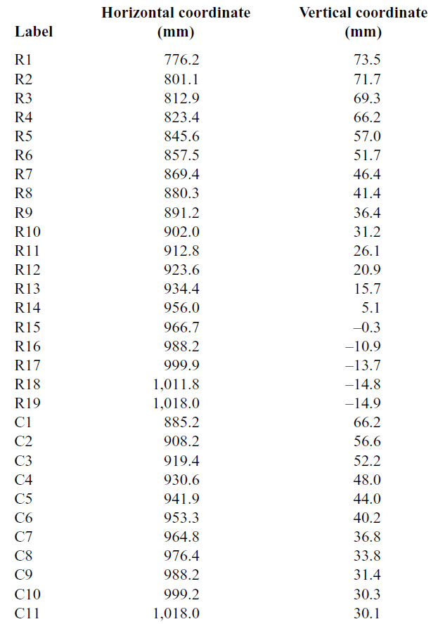
Figure 4 shows the submerged inlet model with and without a diverter installed in the wind tunnel, with a total length of 1300mm. For actual flight, the inlet is positioned at the bottom of the fuselage. In the experiments, the inlet aerodynamic performance was measured by using the widely used rake technique(Reference Seddon and Goldsmith15). At the Aerodynamics Interface Plane (AIP), the performances of the submerged inlet were calculated from the data measured at eight static pressure taps and a total pressure rake (Fig. 5) with 40 pitot tubes. The total pressure rake consisted of eight branches with intervals of 45 $^{\circ}$; the radial positions of the probes are presented in Table 2. The maximum blockage was 4.8% in the internal duct. There were five pitot tubes in each branch, and the outer diameter of the tube was 0.8mm. Additionally, to facilitate the analysis of the inlet flow structure, on the symmetry plane, 19 static pressure taps (labelled R1–R19) were flush mounted on the ramp-side surface, and 11 static pressure taps (labelled C1–C11) were flush-mounted on the cowl-side surface. The coordinates of these static pressure taps are presented in Table 3. All pressure data were measured using an Electronically Scanned Pressure (ESP) transducer system 98RK (Pressure System Inc.). The ESP has a margin error of 0.05% over the full range of calibration. Thus, the maximum error of the measured pressures is estimated to be about ±52Pa over the measurement range of 15psi (103,421Pa). To change the mass flow passing through the inlet, a blockage plug placed at the exit of the entire duct was driven by an electric motor.
Radiuses of radial positions of the total pressure probes

Total pressure rake.

2.3 Inlet performance evaluation parameters
In this paper, the total pressure recovery and the circumferential distortion are used to evaluate the inlet performances. The total pressure recovery  $\sigma$ is defined as
 \begin{equation}\sigma = \frac{{\overline {p_{AIP}^ * } }}{{p_0^ * }},\end{equation}
Locations of static pressure taps

where  $p_0^ * $ is the free stream total pressure and
 $\overline {p_{AIP}^ * } $ is the mass-averaged total pressure at the AIP.
The circumferential distortion descriptor DC 6016 is defined as
 \begin{equation}D{C_{60}} = \frac{{\overline {p_{AIP}^ * } - \overline {p_{60,\min }^ * } }}{{\overline {{q_{AIP}}} }},\end{equation}
where  $\overline {p_{60,\min }^ * } $ is the minimum mass-averaged total pressure in any section of extent 60
 $^{\circ}$, and
 $\overline {{q_{AIP}}} $ is the mass-averaged dynamic pressure at the AIP. The linear interpolation was performed at intervals of 5
 $^{\circ}$ between neighbouring branches of the total pressure rake, to scan all 60
 $^{\circ}$ sections.
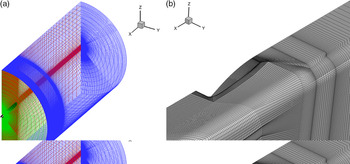
Meshes of the computational domain of the baseline inlet. (a) Full domain, (b) entrance meshes.

2.4 Numerical simulation
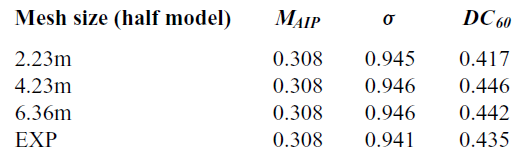
Numerical simulation was employed to examine the change of the forebody boundary layer under different free-stream conditions and to explain the removal of the forebody boundary layer by the submerged diverter. To obtain the forebody boundary-layer parameters and the flow parameters inside the submerged diverter, a Navier–Stokes solver is used to calculate the compressible three-dimensional flow. In solving the governing equations, Roe’s scheme in combination with the MUSCL interpolation method is utilised to obtain the inviscid fluxes at the control surfaces. The governing equations are discretised by a second-order upwind scheme. The turbulent flow is modelled by using the two-equation k– $\omega$–Shear Stress Transport (SST) model(Reference Menter17). The structured meshes of the computational domain are shown in Fig. 6. Table 4 presents the calculated aerodynamic performance using three different meshes and the experimental results of the baseline inlet at M 0 = 0.5,
 $\alpha$ = 0
 $^{\circ}$,
 $\beta$ = 0
 $^{\circ}$, and M AIP = 0.308. It can be seen that the aerodynamic performance of the inlet remains nearly constant for the three meshes, and the simulation results are close to the experimental measurement. The calculated and experimental static pressure distributions along the duct wall and the total pressure recovery distributions at the exit of the inlets with and without a submerged diverter are also given in Figs. 7 and 8, respectively. The comparison indicates that the simulation results are in good agreement with the experimental results. Considering the calculation accuracy and resource consumption, a mesh of 4.23m is recommended for such numerical simulations.
Comparison of calculated and experimental results for the baseline inlet at M 0 = 0.5,  $\alpha$ = 0
 $^{\circ}$,
 $\beta$ = 0
 $^{\circ}$, M AIP = 0.308. (a) Static pressure distributions, (b) total pressure recovery contour.

Comparison of calculated and experimental results for inlet with a submerged diverter at M 0 = 0.5,  $\alpha$ = 0
 $^{\circ}$,
 $\beta$ = 0
 $^{\circ}$, M AIP = 0.308. (a) Static pressure distributions, (b) total pressure recovery contour.

3.0 RESULTS AND DISCUSSION
To examine the effects of the forebody boundary layer on the aerodynamic performance and flow field structure of a submerged inlet, the aerodynamic characteristics of a submerged inlet with and without a submerged diverter under different mass flow rates, free-stream Mach numbers, flight angles of attack and sideslip angles were studied in comparison.
3.1 Removal of the forebody boundary-layer low-energy flow by the submerged diverter
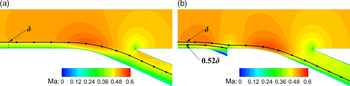
The calculated total pressure recovery contours along the flow direction and the Mach number contours along the symmetry plane of the inlets at M 0 = 0.5,  $\alpha$ = 0
 $^{\circ}$,
 $\beta$ = 0
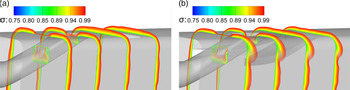
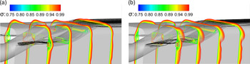
 $^{\circ}$ and M AIP = 0.308 are shown in Figs. 9 and 10, respectively. It can be seen that the boundary layer developed along the aircraft forebody is generally uniform in the spanwise direction, when both the attack angle and the sideslip angle of the free stream are 0
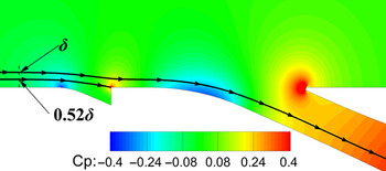
 $^{\circ}$. Most of the low-energy flow associated with the forebody boundary layer is diverted away by the submerged diverter. Along the symmetry plane of the inlet, a low-energy flow below the height of about 0.52
 $\delta$ enters the submerged diverter. Compared with the baseline inlet, the boundary layer entering the submerged inlet with a diverter is much thinner, and the proportion of low-energy flow in the boundary layer is also significantly reduced, which greatly reduces the boundary-layer flow loss on the fore side of the inlet. Meanwhile, because of the much wider entrance of the submerged diverter compared with the submerged inlet, the low-energy flow of the boundary layer involved in the submerged inlet entrance side-edge vortex is reduced, resulting in a small entrance side-edge vortex. Hence, the flow loss induced by the side-edge vortex is reduced.
Calculated total pressure recovery contours along the flow direction, M 0 = 0.5,  $\alpha$ = 0
 $^{\circ}$,
 $\beta$ = 0
 $^{\circ}$ and M AIP = 0.308. (a) Baseline, (b) with the diverter.

Calculated Mach number contours along the symmetry plane of the inlets, M 0 = 0.5,  $\alpha$ = 0
 $^{\circ}$,
 $\beta$ = 0
 $^{\circ}$ and M AIP = 0.308. (a) Baseline, (b) with the diverter.

The forebody boundary-layer low-energy fluids entering the submerged diverter can flow relatively smoothly to both sides of the fuselage. Similar to the submerged inlet, there is also a vortex rolling up around the side edge at the entrance of the submerged diverter, thereby forming a relatively concentrated low-energy flow area near the outer surface of the internal channel. Although the cross-sectional area of the internal channel of the submerged diverter remains nearly the same, the throttle section of the submerged diverter is located at the exit station of the diverter, because of the restraint of the high-energy mainstream flowing along the fuselage. The submerged diverter can divert a portion of the forebody boundary-layer low-energy flow, due to the local low-pressure zone around the fore lip of the submerged diverter (Fig. 11).
Calculated static pressure contours along the symmetry plane of the inlet with a diverter, M 0 = 0.5,  $\alpha$ = 0
 $^{\circ}$,
 $\beta$ = 0
 $^{\circ}$ and M AIP = 0.308.

3.2 Effect of mass flow
Figure 12 shows the dependence of the inlet total pressure recovery and circumferential distortion as a function of the AIP Mach number (flow rate) under the conditions of Mach number M 0 = 0.5,  $\alpha$ = 0
 $^{\circ}$ and
 $\beta$ = 0
 $^{\circ}$. As can be seen from Fig. 12(a), for both the baseline inlet and the inlet with a submerged diverter, the total pressure recovery increases first and then decreases slowly with the increase of AIP Mach number. In the entire experimental range (M AIP = 0.259 ∼ 0.430), the total pressure recovery of the inlet with a submerged diverter is significantly higher than that of the baseline inlet. As shown in Fig. 12(b), with the increase of AIP Mach number, the circumferential distortion DC 60 of baseline inlet and the inlet with a submerged diverter decreases first and then increases generally. Still, the AIP Mach number corresponding to the minimal distortion of the inlet with a submerged diverter is smaller than that of the baseline inlet. The overall DC 60 value of the inlet with a submerged diverter is less than 0.45, and it is much smaller than that of the baseline inlet within the majority of the experimental range (M AIP = 0.25
 $\sim $ 0.35).
Calculated aerodynamic performance using three different meshes and the experimental results of the baseline inlet at M 0 = 0.5,  $\alpha$ = 0
 $^{\circ}$,
 $\beta$ = 0
 $^{\circ}$ and M AIP = 0.308

Effects of AIP Mach number on inlet performance, M 0 = 0.5,  $\alpha$ = 0
 $^{\circ}$ and
 $\beta$ = 0
 $^{\circ}$. (a) σ varies with MAIP, (b) DC60 varies with MAIP.

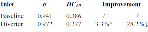
Table 5 presents the performances of the two inlets at the AIP Mach number of 0.31. Compared with the baseline inlet, the total pressure recovery of the inlet with the submerged diverter increases by 3.3%, while the circumferential distortion decreases by 28.2%. Nevertheless, the total pressure recovery of the submerged inlet with the submerged diverter is still lower than that of the conventional pitot S-shaped inlet at this speed (Reference Xie and Guo18-Reference Maghsoudi, Vaziry and Mahmoodi22).
Comparison of inlet performances (M 0 = 0.5,  $\alpha$ = 0
 $^{\circ}$,
 $\beta$ = 0
 $^{\circ}$, M 2 = 0.31)

Figure 13 shows the total pressure contours of the baseline inlet at different AIP Mach numbers. At a low AIP Mach number (0.259, Fig. 13(a)), there is a relatively high total pressure zone at the top (the cowl side) of the AIP near the central cone, and the local largest low-energy flow zone exists at the bottom (the ramp side). As the AIP Mach number increases to 0.430, the relatively high total pressure zone gradually migrates from the cowl side to the ramp side, and the local largest low-energy flow zone migrates from the ramp side to the cowl side, correspondingly. A low-energy flow of the forebody boundary layer swallowed into the internal passage(Reference Sun, Guo and Wu7) would result in a large area of low total pressure at the bottom of the AIP under the strong adverse pressure gradient along the ramp side (Fig 14).
Total pressure contours at AIP of the baseline inlet, M 0 = 0.5,  $\alpha$ = 0
 $^{\circ}$ and
 $\beta$ = 0
 $^{\circ}$. (a) M AIP = 0.259, (b) M AIP = 0.308, (c) M AIP = 0.430.

Moreover, the width of the captured flow by the submerged inlet is obviously larger than the maximum width of the entrance(Reference Sun, Guo and Wu7). The corresponding boundary-layer flow leads to a pair of vortices in the inlet, originated from both side edges of the entrance (side-edge vortex). The low-energy flow involved in the side-edge vortices on both sides converges gradually in the upper region of the internal passage, thus forming a relatively low total pressure region. Hence, the flow pattern of the submerged inlet is mainly determined by the ratio of the swallowed boundary layer to the captured flow, the strength of the adverse pressure gradient and the strength of the side-edge vortex. At a low AIP Mach number (0.259), the ratio of the swallowed boundary layer to the captured flow is large, and the strength of the adverse pressure gradient along the ramp-side wall at the entrance is strong. Furthermore, the total pressure recovery at the bottom of the exit is around 0.906, which is only slightly higher than the ratio of the local static pressure to the free stream total pressure 0.899. This indicates that there may be a considerable three-dimensional separation on the ramp-side wall near the exit, generating the large low-energy flow zone at the bottom. The circumferential distortion may exceed the tolerance of turbine engines, which could limit the stable margin of the engine operating at low rotating speeds. At a high AIP Mach number, a large low energy flow zone exists at the top because of the great strength of the side-edge vortex induced by the large speed of the flow around the side edge. In comparison, the total pressure losses in the local largest low-energy flow zone at a low AIP Mach number (0.259, Fig. 13(a)) and a high Mach number (0.430, Fig. 13(c)) are all larger than that at a medium AIP Mach number (0.308, Fig. 13(b), near the engine matching Mach number). Therefore, for the baseline inlet, both too small and too large a Mach number at the exit will cause an increase of the total pressure loss and distortion.
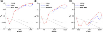
Based on the static pressure distributions along the ramp side and cowl side surfaces shown in Fig. 14, it can be seen that there is an obvious local acceleration of the flow through the initial convex surface near the fore lip of the entrance on the ramp side. At M AIP = 0.308, if the effect of surface curvature on the normal pressure gradient of the boundary layer is neglected, the Mach number of local inviscid flow at the second measuring point on ramp side of the baseline inlet can be estimated to be as high as 0.588, which is significantly higher than that of the free stream (0.5). The flow on the ramp side is subjected to an adverse pressure gradient from R2 to R17, especially the strong adverse pressure gradient between R2 and R5 at the entrance. It can be concluded that the local accelerating zone near the fore lip of the entrance will aggravate the adverse pressure gradient of the boundary layer and induce total pressure losses. Besides, it should be noted that, because of the existence of a central cone near the exit of the studied inlet (Fig. 2), the internal passage contracts and the subsonic flow accelerates, resulting in a decrease of the static pressure on both the upper and lower wall surfaces. Subsequently, the static pressure on the upper wall rises again, which is caused by the local deceleration of the flow downstream of the convex surface of the upper wall. The static pressure on the lower wall drops continuously because of the local accelerating flow.
Static pressure distributions on the wall surfaces of the baseline inlet, M 0 = 0.5,  $\alpha$ = 0
 $^{\circ}$ and
 $\beta$ = 0
 $^{\circ}$. (a) M AIP = 0.259, (b) M AIP = 0.308, (c) M AIP = 0.430.

The trends of the total pressure distribution variations at the exit (Fig. 15) and the static pressure distributions on the wall (Fig. 16) of the inlet with a submerged diverter are similar to that of the baseline inlet. Moreover, the relatively low total pressure region at the bottom of the AIP is due to the development of the newly generated boundary layer along the ramp side surface subjected to the adverse pressure gradient. Meanwhile the low-energy flow at the top of the AIP is mainly due to the accumulation of the low-energy flow induced by the development of the side-edge vortices. By comparison, the total pressure recovery at AIP is significantly increased because of the removal of the forebody boundary-layer low-energy flow by the submerged diverter. Meanwhile, the scale of the three-dimensional separation zone on the ramp-side wall near the exit is smaller than that of the baseline inlet. Also, compared with the baseline inlet, the average static pressure coefficient at the AIP of the inlet with a submerged diverter increases significantly, which indicates that the latter has a larger diffusing capacity.
Total pressure contours at AIP of the inlet with a submerged diverter, M 0 = 0.5,  $\alpha$ = 0
 $^{\circ}$ and
 $\beta$ = 0
 $^{\circ}$. (a) M AIP = 0.234, (b) M AIP = 0.309, (c) M AIP = 0.451.

Static pressure distributions on the wall surfaces of the inlet with a submerged diverter, M 0 = 0.5,  $\alpha$ = 0
 $^{\circ}$ and
 $\beta$ = 0
 $^{\circ}$. (a) M AIP = 0.234, (b) M AIP = 0.309, (c) M AIP = 0.451.

3.3 Effect of free-stream speed
Figure 17 displays the variations of the total pressure recovery and circumferential distortion descriptor with the free-stream Mach number, at  $\alpha$ = 0
 $^{\circ}$,
 $\beta$ = 0
 $^{\circ}$ and M AIP = 0.31. As shown in Fig. 17(a), for the baseline inlet and the inlet with a submerged diverter, the total pressure recovery decreases as the free-stream Mach number increases. In the range of the free-stream Mach number (0.3
 $\sim $ 0.6), the total pressure recovery of the inlet with a submerged diverter is significantly larger than that of the baseline inlet, and the gap between the two increases as the free-stream Mach number increases. As can be seen from Fig. 17(b), with the increase of the free-stream Mach number, the circumferential distortion of the baseline inlet decreases slightly initially and then increases, while that of the inlet with a submerged diverter remains nearly unchanged initially and then decreases. The circumferential distortion of the inlet with a submerged diverter is generally smaller than that of the baseline inlet, especially under high free-stream Mach numbers. At M 0 = 0.6, compared with the baseline inlet, the total pressure recovery of the inlet with a submerged diverter is improved by 4.8%, and the circumferential distortion is reduced by 50.2%.
Effects of free-stream Mach number on inlet performance,  $\alpha$ = 0
 $^{\circ}$,
 $\beta$ = 0
 $^{\circ}$ and M AIP= 0.31. (a)
 $\sigma$ varies with M 0, (b) DC 60 varies with M 0.

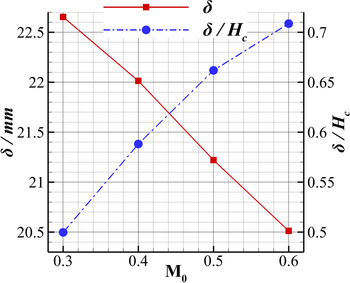
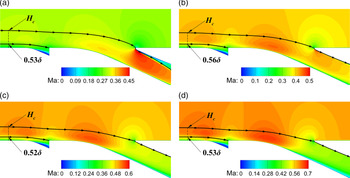
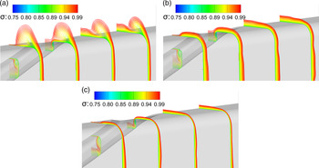
Figure 18 gives the total pressure contours of the baseline inlet at different free-stream Mach numbers. As the free-stream Mach number increases from 0.3 to 0.6, the large low-energy flow zone migrates from the cowl side to the ramp side, which is similar to the change of the flow pattern observed with a decrease of the exit Mach number (Fig. 13). On the other hand, the simulation results show that as the free-stream Mach number increases, although the forebody boundary-layer thickness decreases slightly, the ratio of the boundary-layer thickness to the height of the captured flow  $\delta$/H c on the symmetry plane increases (Fig. 19). For a fixed inlet exit Mach number, a high free-stream Mach number has a stronger effect to the height of the captured flow than to the reduction of the boundary-layer thickness. For the inlet with a submerged diverter, the change of the flow pattern induced by the increase of the free-stream Mach number (Fig. 20) is also similar to that induced by the decrease of the exit Mach number (Fig. 15). However, the area of high total pressure zone is significantly larger than the baseline inlet case, especially for the region near the bottom. The Mach number contours along the symmetry plane of the inlet with a submerged diverter under different free-stream Mach numbers are shown in Fig. 21. It can be seen that the ratio of the height of the forebody boundary-layer low-energy flow entering into the submerged diverter to the height of the inlet captured flow increases with the increase of the free-stream Mach number. As a result, the magnitude of the aerodynamic performance improvement for the inlet with the submerged diverter, in comparison with the baseline inlet, increases with the increase of the free-stream Mach number. Hence, with the increase of the free-stream Mach number, the proportion of low-energy flow of the forebody boundary layer in the captured airflow increases, the performance of the baseline inlet deteriorates and the magnitude of improvement for the inlet with a submerged diverter increases.
Total pressure contours at AIP of the baseline inlet,  $\alpha$ = 0
 $^{\circ}$,
 $\beta$ = 0
 $^{\circ}$ and M AIP = 0.31. (a) M 0 = 0.3, (b) M 0 = 0.5, (c) M 0 = 0.6.

Effects of the free-stream Mach number on forebody boundary-layer thickness and the ratio of the boundary-layer thickness to the height of the inlet captured flow ( $\delta$/H c) at the symmetry plane.

Total pressure contours at AIP of the inlet with a submerged diverter,  $\alpha$ = 0
 $^{\circ}$,
 $\beta$ = 0
 $^{\circ}$ and M AIP = 0.31. (a) M 0 = 0.3, (b) M 0 = 0.5, (c) M 0 = 0.6.

Mach number contours of the symmetry plane with submerged diverter under different free-stream Mach numbers. (a) M 0 = 0.3, (b) M 0 = 0.4, (c) M 0 = 0.5, (d) M 0 = 0.6.

3.4 Effect of angle-of-attack
Fig. 22 displays the dependence of the inlet total pressure recovery and circumferential distortion descriptor on the angle-of-attack at M 0 = 0.5,  $\beta$ = 0
 $^{\circ}$ and M AIP = 0.31. As can be seen from Fig. 22(a), for both the baseline inlet and the inlet with a submerged diverter, the total pressure recovery decreases first and then increases with the increase of angle-of-attack. As shown in Fig. 22(b), the circumferential distortion of the baseline inlet increases first and then decreases, while that of the inlet with a submerged diverter changes only slightly. By comparison, both the total pressure recovery and circumferential distortion are improved in the range of angle-of-attack –6 ∼ 8
 $^{\circ}$.
Effects of angle-of-attack on inlet performance at M 0 = 0.5,  $\beta$ = 0
 $^{\circ}$ and M AIP = 0.31. (a)
 $\sigma$ varies with
 $\alpha$, (b) DC 60 varies with α.

Total pressure contours at the AIP of the baseline inlet at M 0 = 0.5,  $\beta$ = 0
 $^{\circ}$ and M AIP = 0.31. (a)
 $\alpha$ = –6
 $^{\circ}$, (b)
 $\alpha$ = 0
 $^{\circ}$, (c)
 $\alpha$ = 8
 $^{\circ}$.

Figure 23 gives the total pressure contours at AIP for the baseline inlet at different incidences. It can be seen that the areas of high total pressure at the exit of the inlet at  $\alpha$ = –6
 $^{\circ}$ and 8
 $^{\circ}$ are larger than that at
 $\alpha$ = 0
 $^{\circ}$. However, the mechanisms are different. Demonstrated by the calculated total pressure contours for the baseline inlet (Fig. 24), when
 $\alpha$ = 8
 $^{\circ}$, the direct incoming up-wash flow on the windward side induces a portion of the forebody boundary layer to move away from the entrance, and it also makes it easy for the submerged inlet to swallow more potential flow. In contrast, when
 $\alpha$ = –6
 $^{\circ}$, a pair of vortices are generated near both sides of the fuselage on the leeward side. On the one hand, near the symmetry plane, the secondary flow induced by this pair of vortices allows more potential fluid to deflect into the inlet entrance, which reduces the difficulty of capturing the high-energy flow. On the other hand, near the wall, the secondary flow sweeps a portion of the forebody boundary layer to the two sides, which reduces the thickness of the boundary layer facing the inlet entrance. For the inlet with a submerged diverter, because of the removal of the forebody boundary-layer low-energy flow (Fig. 25), the performance improvements induced by the favourable flow patterns at
 $\alpha$ = –6
 $^{\circ}$ and 8
 $^{\circ}$ are both reduced slightly. Nevertheless, compared with the baseline inlet, the total pressure at the exit of the inlet is significantly higher, and the circumferential distribution is more uniform (Fig. 26).
Calculated total pressure recovery contours for the baseline inlet, M 0 = 0.5,  $\beta$ = 0
 $^{\circ}$ and M AIP = 0.31. (a)
 $\alpha$ = –6
 $^{\circ}$, (b)
 $\alpha$ = 0
 $^{\circ}$, (c)
 $\alpha$ = 8
 $^{\circ}$.

Calculated total pressure recovery contours for the inlet with a diverter, M 0 = 0.5,  $\beta$ = 0
 $^{\circ}$ and M AIP = 0.31. (a)
 $\alpha$ = –6
 $^{\circ}$, (b)
 $\alpha$ = 0
 $^{\circ}$, (c)
 $\alpha$ = 8
 $^{\circ}$.

Total pressure contours at AIP of the inlet with a submerged diverter, M 0 = 0.5,  $\beta$ = 0
 $^{\circ}$ and M AIP = 0.31. (a)
 $\alpha$ = –6
 $^{\circ}$, (b)
 $\alpha$ = 0
 $^{\circ}$, (c)
 $\alpha$ = 8
 $^{\circ}$.

Effects of yaw on submerged inlet performance, M 0 = 0.5,  $\alpha$ = 0
 $^{\circ}$ and M AIP = 0.31. (a) σ varies with
 $\beta$, (b) DC60 varies with
 $\beta$.

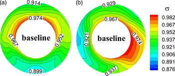
Total pressure contours at AIP of the baseline inlet, M 0 = 0.5,  $\alpha$ = 0
 $^{\circ}$ and M AIP = 0.31. (a)
 $\beta$ = 0
 $^{\circ}$, (b)
 $\beta$ = 4
 $^{\circ}$.

Calculated total pressure recovery contours for the baseline inlet, M 0 = 0.5,  $\alpha$ = 0
 $^{\circ}$ and M AIP = 0.31. (a)
 $\beta$ = 0
 $^{\circ}$, (b)
 $\beta$ = 4
 $^{\circ}$.

Total pressure contours at the AIP of the inlet with a submerged diverter, M 0 = 0.5,  $\alpha$ = 0
 $^{\circ}$ and M AIP = 0.31. (a)
 $\beta$ = 0
 $^{\circ}$, (b)
 $\beta$ = 4
 $^{\circ}$.

Calculated total pressure recovery contours for the inlet with a diverter, M 0 = 0.5,  $\alpha$ = 0
 $^{\circ}$ and M AIP = 0.31. (a)
 $\beta$ = 0
 $^{\circ}$, (b)
 $\beta$ = 4
 $^{\circ}$.

3.5 Effect of yaw
Figure 27 shows the variations of the inlet total pressure recovery and circumferential distortion descriptor with the yaw, at M 0 = 0.5,  $\alpha$ = 0
 $^{\circ}$,
 $\beta$ = 0
 $^{\circ}$ and M AIP = 0.31. When the yaw increases to 4
 $^{\circ}$, the total pressure recovery of the baseline inlet increases slightly, while that of the inlet with submerged diverter remains nearly unchanged. Meanwhile, the circumferential distortion of both cases increases. At
 $\beta$ = 4
 $^{\circ}$, compared with the baseline inlet, the total pressure recovery of the inlet with a submerged diverter is improved by 2.8%, and the circumferential distortion is reduced by 25.6%.
Figure 28 shows the total pressure contours of the baseline inlet at different yaws. With the aid of the calculated total pressure contours for the baseline inlet shown in Fig. 29, as the yaw increases to 4 $^{\circ}$, the effective forebody length for the development of the boundary layer decreases, which reduces the thickness of the forebody boundary layer. Meanwhile, the leeward side-edge vortex is strengthened, and the windward one is weakened. The area of the high total pressure zone, which is located at the windward side, is larger than the area of the high total pressure zone at
 $\beta$ = 0
 $^{\circ}$. For the inlet with a submerged diverter, the width of the submerged diverter is 2.49 times the width of the entrance, which is wide enough for the removal of the forebody boundary layer, even under a yaw of 4
 $^{\circ}$ (Fig. 30). Hence, the reduction of the effective forebody length under
 $\beta$ = 4
 $^{\circ}$ hardly effects the total pressure recovery under the condition of
 $\beta$ = 0
 $^{\circ}$. In addition, the majority of the high total pressure zone is still located at the windward side.
4.0 CONCLUSION
In this paper, a submerged inlet with/without a diverter was employed to study the effects of the forebody boundary layer on the flow pattern and aerodynamic performance. The main conclusions are as follows:
(1) In a wide operational envelope of M 0 = 0.3 ∼ 0.6,
$\alpha$ = –6 ∼ 8$^{\circ}$ and $\beta$ = 0 ∼ 4$^{\circ}$, with the removal of the forebody boundary-layer low-energy flow using a submerged diverter, both the total pressure loss and the circumferential distortion can be significantly reduced. The improvement is more significant with the increase of free-stream Mach number.(2) At M 0 = 0.5,
$\alpha$ = 0$^{\circ}$, $\beta$ = 0$^{\circ}$ and M AIP = 0.31, compared with the baseline inlet, the total pressure recovery of the inlet with a submerged diverter increases by 3.3%, and the circumferential distortion descriptor DC 60 decreases by 28.2%.(3) The forebody boundary layer has a strong impact on the performance of the submerged inlet at AIP, beyond the ramp side. The local acceleration zone near the fore lip increases the adverse pressure gradient at the entrance and increases the total pressure loss of the boundary-layer flow on the ramp side. The low-energy flow induced by the pair of the side edge vortices is also one of the main causes of flow loss.
(4) By removal of the forebody boundary-layer low-energy flow using a submerged diverter, the flow loss is mainly caused by the newly generated boundary layer along the ramp side surface subjected to the adverse pressure gradient and the pair of side-edge vortices at the entrance. However, the total pressure recovery of the submerged inlet with a submerged diverter is still lower than that of the conventional pitot S-shaped inlet.


ACKNOWLEDGEMENTS
This work is supported by the National Nature Science Foundation of the People’s Republic of China through grant no. 11002069.