Introduction
Nowadays, antennas must be small, have a low profile, with high operating bandwidth and considerable directivity. Low profile patch antennas with simple structures and with the capability of fabricating on printed circuit boards (PCB) can be considered as suitable alternatives. However, two disadvantages of these antennas are narrow bandwidth and low directivity. To achieve wide bandwidth and yet a small size, patch antennas are made on thick high dielectric constant substrates [Reference Schaubert, Pozar and Adrian1]. A high dielectric constant leads to an increased cost of fabrication with the propagation of unwanted modes in the substrate, which affects the antenna's radiation characteristics [Reference Schaubert, Pozar and Adrian1, Reference Horák and Raida2].
Another way to overcome these disadvantages is by using artificial metamaterials [Reference Palandöken3–Reference Patel and Kosta9]. There are numerous classifications for metamaterial structures in the literature and electromagnetic band gaps (EBG) are categorized as one of these classifications [Reference Rahmat-Samii and Mosallaei10, Reference Liu and Alexopoulos11].
Applying EBG structures leads to many new antennas and applications [Reference Kumar, Kumar, Mohan and Gupta12–Reference Verma, Singh, Srivastava, Patil and Kanaujia14]. These structures can remove the unwanted effects of substrates and cause gain enhancement [Reference Kavousi, Rashed-Mohassel and Edalatipour15–Reference Bakhtiari, Sadeghzadeh and Moghadasi17].
They are used to control the propagation of electromagnetic waves. The application of EBG is based on wave propagation either as a filter or as a defect in a periodic structure. The latter is useful in antenna applications to radiate EM waves in the desired direction at a specified frequency. EBGs usually behave as band-stop filters [Reference Gao, Wu and Mao18, Reference Palandoken19], rejecting the energy flow over a fixed band of frequencies and can be used in absorption applications [Reference Deng, Li and Chen20, Reference Ren, Gong and Jiang21]. Also, they can be used in optical applications [Reference Patel, Ladumor, Parmar and Guo22, Reference Patel, Ladumor and Katrodiya23]. When a defect is introduced affecting the periodicity of the structure; a region of localized electromagnetic energy is established. The patch antenna is considered as the defect of a structure.
In this paper, the design of an antenna for X-band with an increase of the bandwidth of a simple rectangular microstrip antenna is contemplated. In many previous works [Reference Li and Behdad24–Reference Mishra, Sahu, Parashar and Pathak26], substrates or superstrates have been used to enhance the bandwidth of microstrip antennas. In the present work, to fabricate a broadband microstrip antenna, a single-layer EBG substrate with a ring resonator structure is designed. To do this, the basic shape and dimensions are selected using experimental results and the available data in the literature. To achieve higher bandwidth, the antenna is simulated and optimal parameters such as dielectric thickness and structure dimensions are obtained using a parameter study. Finally, based on simulation results, a patch antenna is fabricated and experimental data are compared with the simulation results.
Design and simulation
EBG unit-cell design and simulation
In this section, the EBG substrate is designed. The equivalent circuit of conventional mushroom EBG structures is shown in Fig. 1. In this EBG structure, vias and the patches play the roles of parallel and series inductors, respectively. The gap between the two elements of the single cell constitutes the series capacitor, while the ground plane and the patch are modeled as a parallel capacitor.
The equivalent circuit of the EBG unit cell: (a) conventional unit cell, (b) ring resonator unit cell.

The equivalent circuit [Reference Gangwar and Gupta27] of the structure used in this article is the same except the EBG structure can better control the inductances [Reference Chen, Ran, Huangfu, Grzegorczyk and Kong28, Reference Islam, Faruque and Islam29].
The bandwidth of the planar antenna associated with the inductance and capacitance of the equivalent circuit is [Reference Yousefi, Mohajer-Iravani and Ramahi30]

where inductances are given by [Reference Patel, Argyropoulos and Kosta8, Reference Jafargholi and Mazaheri31, Reference Paul32]

In which “e” and “f” are ring dimensions and “w” is the width of its strip as shown in Fig. 2. Therefore,

Ring resonator unit cell.

According to equation (2), in addition to the unit-cell dimensions, the ring width, w, is also one of the parameters affecting the inductive property and consequently the resonant frequency of the structure.
To calculate the relative permeability, relative permittivity, and the refractive index of the EBG unit cell, the ring resonator unit cell with boundary conditions given in Fig. 3 is simulated in CST. PEC boundary conditions are used on two sides and PMC was used on the other two, indicating the periodic structure. To excite the structure, two wave ports were used and the relative permeability, the relative permittivity, and the refractive index were extracted from the S parameters [Reference Chen, Grzegorczyk, Wu, Pacheco and Kong33].


Boundary conditions of the simulated ring resonator of the EBG unit cell.

Equations (4) and (5) result in:


With an increased relative permeability and a decreased relative permittivity of a material, wider operation bandwidth can be achieved. The EBG structure can increase the inductance of the circuit and therefore results in bandwidth improvement. Relative permeability of the ring resonator unit cell and a conventional unit cell of the same area are shown in Fig. 4. As can be observed, the relative permeability of the ring resonator unit cell can be changed simply by varying its width, w. This can be ascribed to yet another degree of freedom which leads to increased inductive properties and, as a result, an improved bandwidth.
Relative permeability of the conventional mushroom unit cell and the ring resonator unit cell for different widths of the ring, w (mm).

A parametric study is performed to select the dimensions of the unit cell for a resonant frequency of 9.7 GHz. The parameter “d” is the periodicity of the neighboring cells. The results are illustrated in Tables 1–5. As can be seen, the parameters “e”, “f”, and “d” do not significantly change the resonant frequency while “t” and “w” affect the resonant frequency of the structure. The final values of these parameters for the resonant frequency of 9.7 GHz are shown in Table 6. The constitutive parameters of the optimized EBG unit cell are illustrated in Table 7.
Effect of parameter “e” on the resonant frequency

Effect of parameter “f” on the resonant frequency

Effect of parameter “t” on the resonant frequency

Effect of parameter “d” on the resonant frequency

Effect of parameter “w” on the resonant frequency

Dimensions of the unit cell

Constitutive parameters of the EBG unit cell

EBG substrate design and simulation
To obtain an improved bandwidth for a transmission coefficient, S 21, lower than −10 dB, the rings and vias dimensions and vias locations are the parameters to be optimized. The EBG structure used in this paper (Fig. 5) includes a 4 × 9 array of square rings on a layer of Rogers 4003C (ɛr = 3.58) with 0.8 (mm) thickness and a ground plane of 40 mm × 30 mm. The square patch antenna is designed to operate at 9.7 GHz.
The schematic configuration of the electromagnetic band gap (EBG) layer.

To find the stopband of the EBG substrate, the two ports are assumed at the opposite edges of the bottom and a transmission line is located on the top of the EBG structure. The scattering parameters can then be extracted as shown in Fig. 6. The transmission coefficient, S 21, is calculated by exiting the ports. The stopband, defined for S 21 lower than −10 dB, is obtained as 8.4–10.7 GHz and the resonant frequency is 9.7 GHz as expected.
S 21 versus frequency for the EBG and the schematic representation of the transmission line on the EBG structure.

Patch antenna simulation
A conventional patch antenna is designed at 9.7 GHz. To excite the antenna, a microstrip line with a width of 1.9 mm is used corresponding to an input impedance of 50 Ω. Two gaps with the dimensions of 3.5 (mm) × 0.26 (mm) are used for proper impedance matching as shown in Fig. 7. The 10 dB return loss bandwidth is 0.2 GHz and the gain at resonance is 7.71 dBi. The dimensions of the patch antenna are obtained by antenna design equations [Reference Bhalla and Bansal34]. For impedance matching, the inset feed is used as shown in Fig. 7.
The schematic representation of the conventional antenna.

The dimensions of the designed antenna at 9.7 GHz are given in Table 8.
Dimensions of the antenna

Results and discussion
An EBG ring resonator was designed and simulated in this work. This EBG structure has the potential to better control the inductive properties and therefore increase the bandwidth. The bandwidth of a microchip patch antenna in the X-band is then increased by only one substrate. To achieve this, an array of 4 × 9 was designed and simulated.
The simulated reflection coefficient, S 11, and maximum directivity of the conventional patch antenna with and without the EBG substrate are illustrated in Fig. 8. As can be observed, the antenna bandwidth with the EBG substrate is 1.8 GHz which is increased to about 1.6 GHz, and the maximum directivity fluctuations of the metamaterial antenna are less than the conventional antenna in the desired bandwidth. As it is observed in Fig. 8, it can be concluded that the EBG substrate antenna can operate well in all frequencies of the bandwidth compared with the conventional patch antenna. Therefore, with the EBG substrate, a wideband antenna is achieved which is useful in broadband applications. Furthermore, maximum directivity for the patch antenna with EBG substrate is 8.43 dBi and the 3 dB bandwidth covers the entire X-band frequencies which are prominent in industrial and military applications.
Reflection coefficient and maximum directivity of the patch antenna with and without the EBG substrate.

The radiation characteristics of the proposed antenna are also discussed. The corresponding radiation pattern for the antenna with the EBG substrate at 9.7 GHz is illustrated in Fig. 9(a). The polarization of the individual antenna is linear and has not been changed when the EBG structure is used as the substrate. Figure 9(a) shows that the directivity of the metamaterial antenna is increased by 0.72 dB and the back lobe level is higher than the conventional antenna. The cross-polar radiation pattern of the metamaterial antenna is increased at some angles in comparison to a normal antenna while it is decreased in some other directions.
(a) Radiation pattern of the patch antenna with and without the EBG substrate at 9.7 (GHz). (b) The efficiency of the patch antenna with and without the EBG substrate.

Figure 9(b) shows that the radiation efficiency of the EBG antenna is significantly higher than typical antenna efficiency over the entire bandwidth. The radiation efficiency is well above 0.6 (60%) for the X-band frequency range and yet with favorable directivity for all frequencies in the bandwidth. Therefore, it can be used in broadband antenna applications.
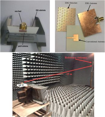
The desired antenna was fabricated and the experiments were performed in an anechoic chamber as shown in Fig. 10. The schematic representation of the experimental set up is shown in Fig. 11. To obtain the radiation pattern, the antenna was placed in a chamber with a length of 15 m, where the separation of the transmitting antenna and the antenna under test exceeds the far-field distance criteria. The structure of the patch antenna with the EBG substrate has been examined using simulation as well as measured data. Figure 12 shows the measured and simulated radiation patterns and S 11 of the patch antenna with the metamaterial substrate. The return loss bandwidth below −10 dB of the EBG antenna is around 1.8 GHz. The measured return loss of EBG antennas reveals a slight shift in the resonances toward higher frequencies than those designated by simulation. This shift is attributed to fabrication inaccuracies and the connector assembly. The simulation and measured results are in good agreement.
Construction and experimental setup.

Schematic representation of the experimental setup.

(a) The simulated and measured radiation pattern of EBG antenna, (b) The simulated and measured S 11 of EBG antenna.

Table 9 presents a comparison of bandwidths and gain improvement, sizes, and previously reported works. It is concluded that the present work improves the bandwidth for approximately 1.6 GHz and the directivity for about 0.72 dB. Also, compared with previous works in the X-band [Reference Patel, Argyropoulos and Kosta8, Reference Joshi, Pattnaik, Devi and Lohokare35–Reference Rahim and Xu38], the structure is smaller in size and more simple with fewer numbers of layers. As for the effects of metamaterial substrate on radiation pattern, previous works show some squint and deviation. In the present paper, although the gain of EBG structure does not show a drastic increase, it does not affect the shape of the radiation pattern, which is crucial in data transmission, industrial, and military applications.
Comparison of the performance of the presented EBG antennas in previous reports and this work

Conclusion
A microstrip antenna with an EBG structure as a substrate was designed and fabricated in the X-band. Experimental results were compared with simulation data and good agreement was observed. Using the ring resonant structure in the EBG substrate increases the inductances of the structure in comparison with conventional mushroom EBG structures which is a key parameter in the design. This structure has better control of resonant frequency and its larger inductances result in a smaller size for a given resonant frequency. Therefore, it can be used when miniaturization application is contemplated. CST software and parametric study were used to obtain optimal dimensions of the design. A ring-shaped metallic is used for the unit cell of the EBG structure. The bandwidth of a simple rectangular microstrip antenna was increased by as much as 1.6 GHz. Furthermore, the result is a dual-band structure; with two resonances at 9.8 and 10.8 GHz, and the return loss in these frequencies is less than −20 and −14 dB, respectively. The antenna directivity improvement is 0.72 dB. The polarization of the antenna with EBG is not changed compared to an individual antenna. A single EBG layer is used in the structure, which does not significantly affect the height of the antenna despite the use of an artificial ground structure. Furthermore, this simple EBG antenna, while having favorable bandwidth and directivity, is easy to fabricate and has low cost in PCB processing, which makes it suitable for military and industrial applications.
 Omid Borazjani received his B.S and M.S degree in Electrical Telecommunication from the Islamic Azad University of Bushehr in 2006 and 2009. Now he is a Ph.D. student of Science & Research Branch, Islamic Azad University, Tehran. He has been a senior researcher and lecturer at the Islamic Azad University of Bushehr from 2009. His research interests are microstrip antenna design, microwave passive and active circuits, RF MEMS. E-mail: omidborazjani62@gmail.com
 Mohammad Naser-Moghadasi was born in Saveh, Iran, in 1959. He received the B.Sc. degree in Communication Engineering in 1985 from Leeds Metropolitan University (formerly Leeds Polytechnic), UK. Between 1985 and 1987, he worked as an RF design engineer for the Gigatech Company in Newcastle Upon Tyne, UK. From 1987 to 1989, he was awarded a full scholarship by the Leeds Educational Authority to pursue an M. Phil. degree studying in CAD of Microwave circuits. He received his Ph.D. degree in 1993, from the University of Bradford, UK. He joined Islamic Azad University, at Science & Research Branch, Iran, where currently he is an Associate Professor and Head of the Telecommunications group. His main areas of interest in research are microstrip antenna, microwave passive and active circuits, RF MEMS. He has so far published over 160 papers in different journals and conferences. E-mail: mn.moghaddasi@srbiau.ac.ir
 Jalil Rashed-Mohassel was born in Birjand, Iran and received his Ph.D. degree in Electrical Engineering from the University of Michigan, Ann Arbor in 1982. His research interests include antennas, EM theory, and EMC/EMI. In 1994, he joined the University of Tehran where he is doing teaching and research as a professor in the school of ECE. He is the author of three books and has published more than 200 papers in refereed journals and conference proceedings. He is a principal member of the Center of Excellence on Applied Electromagnetic Systems (CEAES) and the director of the microwave laboratory. He is a distinguished professor and the recipient of several university and national prizes. Corresponding author. E-mail: jrashed@ut.ac.ir
 Ramazanali Sadeghzadeh received the B.Sc. degree in Telecommunication Engineering from K. N. Toosi University of Technology, Tehran, Iran, in 1984; the M.Sc. degree in Digital Communication Engineering from the University of Bradford, Bradford, UK, and the University of Manchester Institute of Science and Technology (UMIST), Manchester, UK, as a joint program in 1987; and the Ph.D. degree in Electromagnetic and Antenna from the University of Bradford in 1991. During 1992–1997, he worked as a Postdoctoral Research Assistant in the field of propagation, electromagnetic, antenna, and wireless communication at the University of Bradford. From 1984 to 1985, he was with Iran Telecommunication Company, Tehran, Iran, working on networking. Since 1997, he has been with the Faculty of Electrical and Computer Engineering, K. N. Toosi University of Technology. He has published more than 200 referable papers in international journals and conferences. E-mail: sadeghz@eetd.kntu.ac.ir