1. Introduction
Hybrid robots represent mechanical systems composed of several modules, usually with serial or parallel architectures [Reference Wang, Li, Yang, Hu and Zhao1, Reference Kumar, Müller and Kirchner2]. Among them are relative manipulation systems, where these modules are placed individually on the base and operate together [Reference Van Toan and Khoi3–Reference Wu, Wang and Li5]. Such an arrangement improves the functional characteristics of the hybrid robot, which would be unreachable when using the modules separately or connecting them together. These characteristics include increased workspace dimensions and the reconfiguration ability depending on the application [Reference Huang, Deng, Li and Liu6, Reference Carbonari, Callegari, Palmieri and Palpacelli7]. Thanks to these benefits, hybrid robots with relative manipulation have become widespread in machining [Reference Liu, Liu, Xiao, Tian, Ma and Li8, Reference Ma, Xiao, Liu, Liu and Tian9], cooperative assembling [Reference Dogar, Spielberg, Baker and Rus10, Reference He, Wu and Liu11], additive technologies [Reference Isa and Lazoglu12, Reference Zhao, Zhu, He and Guo13], and medicine [Reference Saeidi, Opfermann, Kam, Wei, Leonard, Hsieh, Kang and Krieger14, Reference Asadizeidabadi, Hosseini, Vetshev, Osminin and Hosseini15].
Workspace analysis of robotic systems, including the hybrid robots mentioned above, is a fundamental problem of their design and performance evaluation [Reference Russo and Ceccarelli16–Reference Li, Yang, Xu and Ye18]. The workspace defines the region where the robot can effectively perform manipulations, maintaining specified accuracy and stiffness or avoiding singularities [Reference Erastova19]. Correct workspace determination enhances robot performance, prevents collisions between its links, and ensures safe operation. Scholars have proposed various approaches for workspace analysis, typically based on geometrical or numerical techniques [Reference Rosyid, El-Khasawneh and Alazzam20].
Because of the widespread use of hybrid robots in modern applications, the problem of their workspace analysis and optimization has become the subject of many studies in recent years. At the same time, the workspace analysis methods differ according to the design features of the considered robot and the mechanisms of its modules. Thus, Tsai and Joshi [Reference Tsai and Joshi21] and Kucuk [Reference Kucuk22] analyzed workspaces using numerical methods with a random generation of points, which were expected to be inside the workspace. The inverse kinematics was solved for each point, and the condition number of the Jacobian matrix was computed to decide whether to include the point in the workspace. Chaudhury and Ghosal [Reference Chaudhury and Ghosal23] and Zhang and Wei [Reference Zhang and Wei24] followed a similar approach but applied a Monte–Carlo method, which resulted in a more accurate analysis of geometrical and kinematic constraints when solving the optimal design problem. In ref. [Reference Zhang and Wei24], the authors used Monte–Carlo-based numerical optimization to determine the workspace of a manipulator with four degrees of freedom (4-DOF), considering its stiffness and kinematic parameters. Ye et al. [Reference Ye, Wang, Wu, Yue and Zhou25] considered the symmetrical design of a 5-DOF robot to simplify their computations and experimentally verified the results of the workspace analysis on a physical prototype.
Smits et al. [Reference Smits, Reynaerts and Poorten26] studied a hybrid mechanism with a remote center of motion (RCM) applied to robotic eye surgery. During its workspace analysis, the authors examined the end-effector motion relative to the point positioned by another module of the mechanism. Another hybrid surgical robot with five DOFs and an RCM was considered by Pisla et al. [Reference Pisla, Szilaghyi, Vaida and Plitea27], who determined the workspace of each module and then combined the results. The workspace constraints included the restrictions imposed by a medical tool. Rastegarpanah et al. [Reference Rastegarpanah, Rakhodaei, Saadat, Rastegarpanah, Marturi, Borboni and Loureiro28] studied a 9-DOF foot rehabilitation robot with two modules and also combined the workspaces of the modules, including the stiffness criteria in the analysis.
Schreiber and Gosselin [Reference Schreiber and Gosselin29] considered planar mechanisms and followed another approach: the authors determined the workspaces of the individual kinematic chains and found their intersection. Xu et al. [Reference Xu, Cheung, Wang and Zhao30] applied a similar method to a 6-DOF hybrid robot for polishing freeform surfaces and showed it had no singularities in the prescribed task workspace. Singularities were also examined by Zhang et al. [Reference Zhang, Fang, Fang and Jiang31], who analyzed the workspace of a 5-DOF hybrid robot for high-speed machining of aerospace components. The authors applied a numerical approach and considered joint constraints.
Qin et al. [Reference Qin, Liu, Liu, Gao, Sun and Sun32] analyzed the workspace of a hybrid robot composed of two parallel cable-driven mechanisms. The authors considered geometrical and force constraints and determined the wrench-feasible collision-free workspace of the robot. Chawla et al. [Reference Chawla, Pathak, Notash, Samantaray, Li and Sharma33] solved a similar problem for another cable-driven robot, which was applied for 3D printing. The authors checked cable tension and interference between the robot end-effector and printed layers and determined the workspace that met both criteria.
The literature review shows that workspace analysis of hybrid robots with relative manipulation is a comprehensive problem. It is solved using analytical or numerical methods that consider geometric, kinematic, and force constraints, as well as singular configurations. Most existing studies, however, focus mainly on the independent workspace analysis of each module with the subsequent combination of the obtained results. This method can be suitable for computing translation workspaces [Reference Rosyid, El-Khasawneh and Alazzam20], but it becomes more challenging to implement for determining other types of workspaces (orientation or reachable). At the same time, it is relevant to analyze the workspace in the relative motion of the modules, considering their cooperative work and possible interference of their links. This approach is more desirable in practice, where one module typically positions a tool and the other moves a processed object. The workspace analysis performed for the relative configurations of the tool and object ensures proper trajectory planning and safe operation with no collisions between the modules.
This paper shows how to solve this problem for a recently proposed 6-DOF hybrid robot composed of two modules with parallel architectures [Reference Mukhin, Antonov, Fomin, Romdhane, Mlika, Zeghloul, Chaker and Laribi34]. The major contribution of this work is the development of a concise approach that allows computing the workspace in the relative motion of two modules. It considers all mechanical constraints of each module, as well as possible collisions between its links.
The rest of this article has the following structure. Section 2 presents the design of the hybrid robot. Section 3 develops the algorithm of the workspace analysis. Section 4 illustrates the application of this algorithm with multiple examples, verified by computer-aided-design (CAD) simulations. Section 5 discusses some features of the proposed techniques and their potential improvements. Section 6 recaps the results and mentions directions for future studies.
2. Robot design
The considered hybrid robot consists of two separate modules placed above each other (Fig. 1). The upper module is a 4-DOF Delta-type parallel mechanism introduced in ref. [Reference Laryushkin, Erastova, Filippov and Kheylo35] and studied in refs. [Reference Laryushkin36–Reference Laryushkin, Fomin, Antonov, Glazunov, Larochelle, McCarthy and Lusk38]. It includes four kinematic chains (branches) connecting moving platform 2 with base 1: two central branches and two lateral branches. Each branch consists of carriage 3 that translates along linear guide 4. The central branches include rod 5 coupled with carriage 3 and platform 2 by spherical joints. The lateral branches include two similar rods that form a parallelogram sub-chain. Drives 6, placed on the base, actuate carriages 3 and transmit their motion via ball screws 7. This architecture provides moving platform 2 with a 4-DOF Schönflies motion type: three translational DOFs and one rotational DOF about the horizontal axis that points in front of the robot [Reference Laryushkin, Fomin and Antonov37].
Computer model of the considered robot: (a) front view of the robot; (b) carriage of the upper module; (c) carriage of the lower module; (d) lower moving platform.

The lower module is a 2-DOF rotary parallel mechanism with a circular rail inspired by similar mechanisms proposed in refs. [Reference Xu, Xue and Duan39, Reference He, Duan, Qu and Xiao40] and spherical mechanisms that we analyzed in refs. [Reference Laryushkin, Antonov, Fomin and Glazunov41–Reference Brem, Laryushkin, Fomin and Antonov43]. The mechanism has three branches that connect moving platform 8 with base 1: one central branch and two lateral branches. The central branch includes yoke 9 rotating about the vertical axis, which coincides with the axis of circular rail 10. Yoke 9 attaches to platform 8 with a revolute joint, whose axis remains parallel to the horizontal plane. Each lateral branch includes carriage 11, lower bar 12, upper bar 13, and coupler 14. All these links are connected to each other by revolute joints, and their axes are parallel to each other and the horizontal plane. Coupler 14 attaches to platform 8 with a revolute joint, whose axis passes through the center of yoke 9. Drives 15, installed on carriages 11, actuate them via gear wheels 16. This architecture provides moving platform 8 with two rotational DOFs: unlimited rotation about the rail axis and tilt about the horizontal axis of the central branch.
Thus, the hybrid robot has six DOFs in the relative motion of its moving platforms and can be used as a coordinate-measuring machine [Reference Shen, Ren, Huang, Zhang, Zhang and Zhu44, Reference Shang, Liu and Wang45]. The upper moving platform can position a measuring tool or a visual system, while the lower platform can orient a measured object. At the same time, such combination of the two modules improves the rotational capabilities of the robot, which are usually limited when using a single 6-DOF parallel mechanism [Reference Nabavi, Akbarzadeh and Enferadi46]. Compared with a 6-DOF parallel mechanism, lower-DOF modules have simpler architectures with a smaller number of joint constraints that affect the reachable rotational angles of their output links. As a result, the relative rotational angles of these links increase. In the next section, we present an algorithm to analyze the workspace of the hybrid robot.
3. Workspace analysis
To analyze the robot workspace, we will follow a conventional discretization-based approach [Reference Zhou, Niu, Liu and Zhang47]. It relies on sampling the space of the end-effector configurations, solving the inverse kinematics, and checking the constraints. Unlike conventional serial or parallel robots, the considered robot includes two modules performing relative motions. Therefore, we will perform the workspace analysis in this relative motion. It means that we consider the workspace of the upper module relative to the lower one and do not consider their workspaces relative to the base. In this regard, the workspace analysis of the hybrid robot differs from the workspace analysis of serial or parallel robots.
The workspace shape and dimensions depend on mechanical and non-mechanical constraints. The former include joint constraints and link interference, and the latter are determined by singular configurations [Reference Modak and K48]. In this paper, we focus only on the mechanical constraints, while singularities, briefly discussed in Section 5, will be the subject of our upcoming studies. For the considered robot, these constraints are the following:
-
1. Joint constraints of the upper module, including displacement constraints for its carriages and rotational constraints for its spherical joints.
-
2. Joint constraints of the lower module, including collision avoidance for its carriages and rotational constraints for its revolute joints.
-
3. Link interference between the upper and lower modules.
The first two sets of constraints in the list above can be analyzed for each module independently. Therefore, the first step of the workspace analysis is to determine the posture of each moving platform relative to the base, as discussed in the next section.
3.1. Inverse kinematics of the relative motion
Before starting the analysis, we introduce three reference frames (Fig. 2). The first frame,
 $Oxyz$
, is attached to the base. Its
 $Oz$
axis coincides with the axis of the circular rail and points upward. The
 $Ox$
axis points to the left branch of the upper module. The second frame,
 $O_1x_1y_1z_1$
, is attached to the moving platform of the upper module. Its axes are parallel to the corresponding axes of the
 $Oxyz$
frame when the platform is horizontal. The third frame,
 $O_2x_2y_2z_2$
, is attached to the moving platform of the lower module. Its
 $O_2x_2$
and
 $O_2y_2$
axes are parallel to the corresponding axes of the
 $Oxyz$
frame when the platform is not rotated and not tilted. The
 $O_2z_2$
axis passes through point
 $F$
, where the axes of the central branch joints intersect. The origins of all the reference frames can be selected arbitrarily, ensuring that the conditions stated above are satisfied.
Kinematic schemes of the upper (a) and lower (b) modules and their reference frames.

Now, we can specify the relative configuration of the modules using transformation matrix
 $\mathbf{T}$
, which defines the configuration of frame
 $O_1x_1y_1z_1$
relative to
 $O_2x_2y_2z_2$
:
 \begin{align} \mathbf{T} = \begin{bmatrix} \mathbf{R} &\quad \mathbf{p} \\[3pt] \mathbf{0}^{\mathrm{T}} &\quad 1 \end{bmatrix}, \end{align}
where
 $\mathbf{R}$
is a rotation matrix that defines the orientation of frame
 $O_1x_1y_1z_1$
relative to
 $O_2x_2y_2z_2$
;
 $\mathbf{p}$
is a position vector of point
 $O_1$
relative to
 $O_2x_2y_2z_2$
;
 $\mathbf{0}$
is a
 $3 \times 1$
vector of zeros.
The discretization approach of the workspace analysis implies sampling parameters
 $\mathbf{p}$
and
 $\mathbf{R}$
. For example, if we determine the translation workspace, we set constant rotation matrix
 $\mathbf{R}$
and sample the components of vector
 $\mathbf{p}$
. If we determine the orientation workspace, we set constant position vector
 $\mathbf{p}$
and sample the components of rotation matrix
 $\mathbf{R}$
. In this case, it is convenient to parameterize the rotation matrix by three parameters (e.g., roll-pitch-yaw angles [Reference Cao, Huang, Zhou and Ji49] or tilt-and-torsion angles [Reference Bonev and Gosselin50]), simplifying the workspace representation.
Other types of workspaces can be determined by simultaneous discretization of the position and orientation parameters [Reference Zhou, Niu, Liu and Zhang47]. In any case, we assume that position vector
 $\mathbf{p}$
and rotation matrix
 $\mathbf{R}$
have some predefined values, for which we compute displacements in the joints and check the constraints. This computation involves solving the inverse kinematic problem for each module. Thus, we should first determine configurations of the modules relative to the base. We can specify these configurations by transformation matrices
 $\mathbf{T}_1$
and
 $\mathbf{T}_2$
that define the configuration of frames
 $O_1x_1y_1z_1$
and
 $O_2x_2y_2z_2$
relative to
 $Oxyz$
, respectively (Fig. 2):
 \begin{align} \mathbf{T}_1 = \begin{bmatrix} \mathbf{R}_y(\varphi ) &\quad \mathbf{p}_{O_1} \\[3pt] \mathbf{0}^{\mathrm{T}} &\quad 1 \end{bmatrix}, \qquad \mathbf{T}_2 = \begin{bmatrix} \mathbf{I}_3 &\quad l_{OF}\hat {\mathbf z} \\[3pt] \mathbf{0}^{\mathrm{T}} &\quad 1 \end{bmatrix} \begin{bmatrix} \mathbf{R}_z(\alpha ) &\quad \mathbf{0} \\[3pt] \mathbf{0}^{\mathrm{T}} &\quad 1 \end{bmatrix} \begin{bmatrix} \mathbf{R}_x(\beta ) &\quad \mathbf{0} \\[3pt] \mathbf{0}^{\mathrm{T}} &\quad 1 \end{bmatrix} \begin{bmatrix} \mathbf{I}_3 &\quad l_{FO_2}\hat {\mathbf z} \\[3pt] \mathbf{0}^{\mathrm{T}} &\quad 1 \end{bmatrix}, \end{align}
where
 $\varphi$
is the tilt angle of the upper platform;
 $\alpha$
and
 $\beta$
are the pan and tilt angles of the lower platform, respectively;
 $\mathbf{R}_x(\! * \!)$
,
 $\mathbf{R}_y(\! * \!)$
, and
 $\mathbf{R}_z(\! * \!)$
are the rotation matrices about the corresponding axes;
 $\mathbf{p}_{O_1}$
is a position vector of point
 $O_1$
in frame
 $Oxyz$
;
 $l_{OF}$
and
 $l_{FO_2}$
are the distances between the corresponding points;
 $\mathbf{I}_3$
is a
 $3 \times 3$
identity matrix;
 $\hat {\mathbf z} = [0\,0\,1]^{\mathrm{T}}$
.
Matrix
 $\mathbf{T}_1$
shows that the upper module configuration depends on four parameters: angle
 $\varphi$
and three components of vector
 $\mathbf{p}_{O_1}$
. The configuration of the lower module depends on angles
 $\alpha$
and
 $\beta$
: the left and right transformation matrices in the expression of
 $\mathbf{T}_2$
are constant and correspond to the displacements along the
 $Oz$
and
 $O_2z_2$
axes (Fig. 2). Thus, these are angles
 $\alpha$
,
 $\beta$
, and
 $\varphi$
and vector
 $\mathbf{p}_{O_1}$
that should be determined for specified matrix
 $\mathbf{T}$
. The transformation matrices are related by the following equation:
 \begin{align} \mathbf{T}_1 = \mathbf{T}_2 \mathbf{T}. \end{align}
First, we consider the rotational part of Eq. (3). Substituting Eqs. (1) and (2) into this equation and rearranging the terms, we obtain:
 \begin{align} \mathbf{R} &= \mathbf{R}_x^{\mathrm{T}}(\beta ) \mathbf{R}_z^{\mathrm{T}}(\alpha ) \mathbf{R}_y(\varphi ) \end{align}
 \begin{align*} = \begin{bmatrix} \phantom {-}\cos (\alpha )\cos (\varphi ) &\ \ \phantom {-}\sin (\alpha ) &\ \ \phantom {-}\cos (\alpha )\sin (\varphi ) \\[3pt] -\sin (\alpha )\cos (\beta )\cos (\varphi ) - \sin (\beta )\sin (\varphi ) &\ \ \phantom {-}\cos (\alpha )\cos (\beta ) &\ \ -\sin (\alpha )\cos (\beta )\sin (\varphi ) + \sin (\beta )\cos (\varphi ) \\[3pt] \phantom {-}\sin (\alpha )\sin (\beta )\cos (\varphi ) - \cos (\beta )\sin (\varphi ) &\ \ -\cos (\alpha )\sin (\beta ) &\ \ \phantom {-}\sin (\alpha )\sin (\beta )\sin (\varphi ) + \cos (\beta )\cos (\varphi ) \end{bmatrix}. \end{align*}
We can use Eq. (4) to find angles
 $\alpha$
,
 $\beta$
, and
 $\varphi$
for specified rotation matrix
 $\mathbf{R}$
. Let
 $r_{kl}$
be the
 $(k, l)$
-th element of this matrix. Following the method from ref. [Reference Lynch and Park51, app. B], we compute two sets of solutions for these angles:
 \begin{align} \begin{aligned} \alpha &= \textrm {atan2}\Bigl (r_{12}, \sqrt {r_{22}^2 + r_{32}^2}\Bigr ), &&&\alpha &= \textrm {atan2}\Bigl (r_{12}, -\sqrt {r_{22}^2 + r_{32}^2}\Bigr ), \\ \beta &= \textrm {atan2}(\! -r_{32}, r_{22}), &\quad \text{and}\qquad &&\beta &= \textrm {atan2}(r_{32}, -r_{22}), \\ \varphi &= \textrm {atan2}(r_{13}, r_{11}), &&&\varphi &= \textrm {atan2}(\! -r_{13}, -r_{11}), \end{aligned} \end{align}
where
 $\textrm {atan2}(*,*)$
is the two-argument arctangent function [Reference Lynch and Park51, ch. 6].
We select the solution set for which angle
 $\beta \in [-90^\circ , 90^\circ ]$
, where the lower platform is not flipped. Note that Eq. (5) holds as long as
 $\alpha \neq \pm 90^\circ$
, which corresponds to a singular configuration of the robot. In this configuration, the tilt axes of the upper and lower modules become parallel, and the robot loses one rotational DOF in the relative motion; each module, however, does not meet a singularity in this case. At the same time, there is an infinite number of combinations
 $(\beta , \varphi )$
satisfying the considered relative configuration of the modules.
Angles
 $\alpha$
and
 $\beta$
allow us to compute matrix
 $\mathbf{T}_2$
using Eq. (2). Next, we consider the position part of Eq. (3), from where we find vector
 $\mathbf{p}_{O_1}$
:
 \begin{align} \mathbf{p}_{O_1} = l_{OF}\hat {\mathbf z} + \mathbf{R}_z(\alpha ) \mathbf{R}_x(\beta ) \left (l_{FO_2}\hat {\mathbf z} + \mathbf{p}\right ). \end{align}
Thus, we have determined matrices
 $\mathbf{T}_1$
and
 $\mathbf{T}_2$
that specify configurations of the upper and lower modules relative to the base. We can now proceed with the independent analysis of each module and its mechanical constraints.
3.2. Constraints of the upper module
The mechanical constraints of the upper module are due to the limited displacements of its carriages and limited inclination angles of the rods in its spherical joints. Next, we discuss how to compute these displacements and inclination angles.
Let
 $i = 1, \ldots , 4$
be the branch number of the upper module, and let points
 $A_i$
and
 $B_i$
indicate the centers of the spherical joints in the
 $i$
-th branch (Fig. 2a; for branches with the parallelogram sub-chains, we can select these points in the middle of the parallelogram short sides). Vectors
 $\mathbf{p}_{A_i}$
and
 $\mathbf{p}_{B_i}$
define the positions of these points in frame
 $Oxyz$
:
 \begin{align} \mathbf{p}_{A_i} = \begin{bmatrix} \boldsymbol{\mathrm{\rho }}_{A_i} \\[3pt] h_i \end{bmatrix}, \qquad \begin{bmatrix} \mathbf{p}_{B_i} \\[3pt] 1 \end{bmatrix} = \mathbf{T}_1 \begin{bmatrix} \mathbf{r}_{B_i} \\[3pt] 1 \end{bmatrix}, \end{align}
where
 $h_i$
is the carriage displacement; vector
 $\boldsymbol{\mathrm{\rho }}_{A_i}$
defines the
 $x$
and
 $y$
coordinates of point
 $A_i$
in frame
 $Oxyz$
; vector
 $\mathbf{r}_{B_i}$
defines the coordinates of point
 $B_i$
in frame
 $O_1x_1y_1z_1$
. Parameters
 $\boldsymbol{\mathrm{\rho }}_{A_i}$
and
 $\mathbf{r}_{B_i}$
have constant values that depend on the robot geometry.
The distance between points
 $A_i$
and
 $B_i$
is constant and equal to rod length
 $l_{AB}$
, which we assume is identical for each branch. Thus, we can write the following expression:
 \begin{align} \|\mathbf{p}_{A_i} - \mathbf{p}_{B_i}\|^2 = l_{AB}^2. \end{align}
Substituting Eq. (7) into Eq. (8), we compute parameter
 $h_i$
:
 \begin{align} h_i = \pm \sqrt {l_{AB}^2 - \left (x_{B_i} - x_{A_i}\right )^2 - \left (y_{B_i} - y_{A_i}\right )^2} + z_{B_i}, \end{align}
where
 $[x_{A_i}\,y_{A_i}]^{\mathrm{T}} = \boldsymbol{\mathrm{\rho }}_{A_i}$
and
 $[x_{B_i}\,y_{B_i}\,z_{B_i}]^{\mathrm{T}} = \mathbf{p}_{B_i}$
.
The
 $\pm$
sign in Eq. (9) corresponds to the carriage position above or below the moving platform. We select the plus sign for each branch according to the robot design. This design imposes the following constraints on the carriage displacement:
 \begin{align} h_{\mathrm{min}} \leq h_i \leq h_{\mathrm{max}}, \end{align}
where
 $h_{\mathrm{min}}$
and
 $h_{\mathrm{max}}$
are the minimum and maximum values of displacement
 $h_i$
, which we assume identical for each branch.
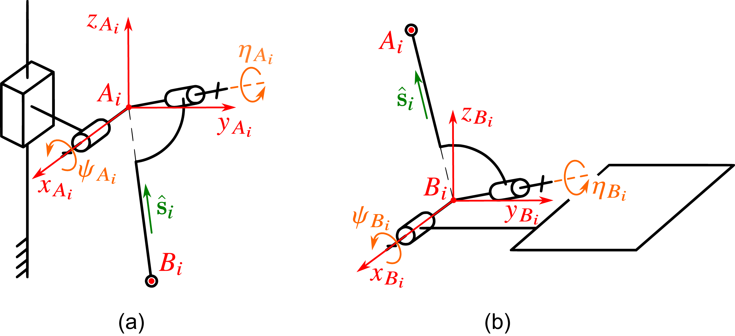
Next, we consider the constraints on the rod inclination in the spherical joints. We start with the carriage spherical joint, centered at point
 $A_i$
. To analyze how this joint constrains the rod motion, we represent the spherical joint as a combination of two revolute joints with intersecting and orthogonal axes (Fig. 3a). We ignore the third rotation of the rod (about line
 $A_iB_i$
) because it does not affect the platform motion.
Equivalent representation of the spherical joints in the
 $i$
-th branch of the upper module: (a) spherical joint of the carriage; (b) spherical joint of the moving platform.

Let
 $\psi _{A_i}$
and
 $\eta _{A_i}$
be the rotational angles in these revolute joints. We introduce the
 $A_ix_{A_i}y_{A_i}z_{A_i}$
reference frame, whose axes
 $A_ix_{A_i}$
and
 $A_iy_{A_i}$
are parallel to the
 $Oxy$
plane and coincident with the axes of the revolute joints when
 $\psi _{A_i} = \eta _{A_i} = 0$
. Constant rotation matrix
 $\mathbf{R}_{A_i}$
determines the orientation of this frame relative to
 $Oxyz$
. According to the robot design, we can write:
 \begin{align} \mathbf{R}_{A_1} = \mathbf{R}_z(\pi /2), \qquad \mathbf{R}_{A_2} = \mathbf{R}_{A_3} = \mathbf{I}_3, \qquad \mathbf{R}_{A_4} = \mathbf{R}_z(\! -\pi /2). \end{align}
Let
 $\hat {\mathbf s}_i$
be a unit vector directed from point
 $B_i$
to point
 $A_i$
, expressed in the
 $Oxyz$
frame. Figure 3a shows that this vector depends on angles
 $\psi _{A_i}$
and
 $\eta _{A_i}$
by the following equation:
 \begin{align} \hat {\mathbf s}_i = \mathbf{R}_{A_i} \mathbf{R}_x(\psi _{A_i}) \mathbf{R}_y(\eta _{A_i}) \hat {\mathbf z}, \end{align}
which we rewrite as below:
 \begin{align} \mathbf{R}_{A_i}^{\mathrm{T}} \hat {\mathbf s}_i = \mathbf{R}_x(\psi _{A_i}) \mathbf{R}_y(\eta _{A_i}) \hat {\mathbf z} = \begin{bmatrix} \sin (\eta _{A_i}) \\[2pt] -\sin (\psi _{A_i})\cos (\eta _{A_i}) \\[2pt] \phantom {-}\cos (\psi _{A_i})\cos (\eta _{A_i}) \end{bmatrix}. \end{align}
The left side of Eq. (13) is known because vector
 $\hat {\mathbf s}_i = (\mathbf{p}_{A_i} - \mathbf{p}_{B_i}) / l_{AB}$
, and it can be computed using Eq. (7). Let
 $\mathbf{R}_{A_i}^{\mathrm{T}} \hat {\mathbf s}_i = [s_i^x \, s_i^y \, s_i^z]^{\mathrm{T}}$
, then we can find the angles using the following expressions:
 \begin{align} \psi _{A_i} = \textrm {atan2}(\! -s_i^y, s_i^z), \qquad \eta _{A_i} = \textrm {asin}(s_i^x), \end{align}
which are valid because
 $|\eta _{A_i}|$
is usually much less than
 $90^\circ$
in physical spherical joints.
Angles
 $\psi _{A_i}$
and
 $\eta _{A_i}$
are limited by the robot design:
 \begin{align} \psi _{A\,\mathrm{min}} \leq \psi _{A_i} \leq \psi _{A\,\mathrm{max}}, \qquad \eta _{A\,\mathrm{min}} \leq \eta _{A_i} \leq \eta _{A\,\mathrm{max}}, \end{align}
where
 $\psi _{A\,\mathrm{min}}$
,
 $\eta _{A\,\mathrm{min}}$
,
 $\psi _{A\,\mathrm{max}}$
, and
 $\eta _{A\,\mathrm{max}}$
are the minimum and maximum values of angles
 $\psi _{A_i}$
and
 $\eta _{A_i}$
, and we assume the minimum and maximum values are identical for each branch.
Constraints in the spherical joints of the moving platform are analyzed in the same way. We represent the spherical joint in the
 $i$
-th branch as a combination of two revolute joints, whose axes intersect orthogonally at point
 $B_i$
(Fig. 3b). Let
 $\psi _{B_i}$
and
 $\eta _{B_i}$
be the rotational angles in these revolute joints. We define the
 $B_ix_{B_i}y_{B_i}z_{B_i}$
reference frame, whose axes
 $B_ix_{B_i}$
and
 $B_iy_{B_i}$
are parallel to the
 $O_1x_1y_1$
plane and coincident with the axes of the revolute joints when
 $\psi _{B_i} = \eta _{B_i} = 0$
. Constant rotation matrix
 $\mathbf{R}_{B_i}$
determines the orientation of this frame relative to
 $O_1x_1y_1$
. We place each frame
 $B_ix_{B_i}y_{B_i}z_{B_i}$
in such a way that
 $\mathbf{R}_{B_i} = \mathbf{R}_{A_i}$
for each
 $i = 1, \ldots , 4$
.
To find angles
 $\psi _{B_i}$
and
 $\eta _{B_i}$
, we follow the same approach as for the carriage spherical joint. We can compose an equation similar to Eq. (12). Its right side should include rotation matrix
 $\mathbf{R}_y(\varphi )$
, which corresponds to the tilt of the upper platform. Therefore, we obtain the following expression:
 \begin{align} \hat {\mathbf s}_i = \mathbf{R}_y(\varphi ) \mathbf{R}_{B_i} \mathbf{R}_x(\psi _{B_i}) \mathbf{R}_y(\eta _{B_i}) \hat {\mathbf z}, \end{align}
which we rewrite as below:
 \begin{align} \mathbf{R}_{B_i}^{\mathrm{T}} \mathbf{R}_y^{\mathrm{T}}(\varphi ) \hat {\mathbf s}_i = \mathbf{R}_x(\psi _{B_i}) \mathbf{R}_y(\eta _{B_i}) \hat {\mathbf z} = \begin{bmatrix} \sin (\eta _{B_i}) \\[2pt] -\sin (\psi _{B_i})\cos (\eta _{B_i}) \\[2pt] \phantom {-}\cos (\psi _{B_i})\cos (\eta _{B_i}) \end{bmatrix}. \end{align}
The right side of Eq. (17) is similar to Eq. (13), and we compute angles
 $\psi _{B_i}$
and
 $\eta _{B_i}$
using expressions similar to Eq. (14). These angles are limited by the robot design:
 \begin{align} \psi _{B\,\mathrm{min}} \leq \psi _{B_i} \leq \psi _{B\,\mathrm{max}}, \qquad \eta _{B\,\mathrm{min}} \leq \eta _{B_i} \leq \eta _{B\,\mathrm{max}}, \end{align}
where
 $\psi _{B\,\mathrm{min}}$
,
 $\eta _{B\,\mathrm{min}}$
,
 $\psi _{B\,\mathrm{max}}$
, and
 $\eta _{B\,\mathrm{max}}$
are the minimum and maximum values of angles
 $\psi _{B_i}$
and
 $\eta _{B_i}$
, and we assume the minimum and maximum values are identical for each branch.
Thus, we have analyzed all mechanical constraints of the upper module. Before proceeding to the lower module, we should make a couple of remarks about the performed analysis:
-
1. To analyze the constraints in the spherical joints, we represent each joint as a combination of two revolute joints with intersecting and orthogonal axes. This representation is not unique. For example, in Fig. 3a, we could assume that the axis of the second revolute joint coincides with the
 $A_iz_{A_i}$
axis when
$\psi _{A_i} = 0$
, instead of the
$A_iy_{A_i}$
axis. In this case, multiplier
$\mathbf{R}_y(\eta _{A_i}) \hat {\mathbf z}$
in the right side of Eq. (12) should be replaced with
$-\mathbf{R}_z(\eta _{A_i}) \hat {\mathbf y}$
. Equations (13) and (14) change too, as well as limits
$\psi _{A\,\mathrm{min}}$
and
$\psi _{A\,\mathrm{max}}$
in Eq. (15).
-
2. The branches with the parallelogram sub-chains include two rods ending with the spherical joints. Each rod in such a parallelogram sub-chain inclines by the same angles. Therefore, angles
$\psi _{A_i}$
,
$\eta _{A_i}$
,
$\psi _{B_i}$
, and
$\eta _{B_i}$
in these branches are computed correctly with our assumption that points
$A_i$
are
$B_i$
are the middle points of the short sides of the parallelograms.


3.3. Constraints of the lower module
The mechanical constraints of the lower module include the limited rotational angles in its revolute joints and the possible collision of its carriages. Next, we show how to find these angles and check the collision.
We start with the central branch that has two revolute joints (Fig. 2b). Angle
 $\alpha$
in the first joint is not constrained: the lower moving platform can rotate unlimitedly about the axis of the circular rail. On the other hand, angle
 $\beta$
is limited by the robot design:
 \begin{align} \beta _{\mathrm{min}} \leq \beta \leq \beta _{\mathrm{max}}, \end{align}
where
 $\beta _{\mathrm{min}}$
and
 $\beta _{\mathrm{max}}$
are the minimum and maximum values of angle
 $\beta$
.
Next, we consider the lateral branches of the lower module. Let
 $j = 1, 2$
be the branch number. For the
 $j$
-th branch, we define three points,
 $C_j$
,
 $D_j$
, and
 $E_j$
, as follows. Point
 $E_j$
is the intersection of the axes of the two revolute joints near the moving platform. Points
 $C_j$
and
 $D_j$
stay in the vertical plane passing through point
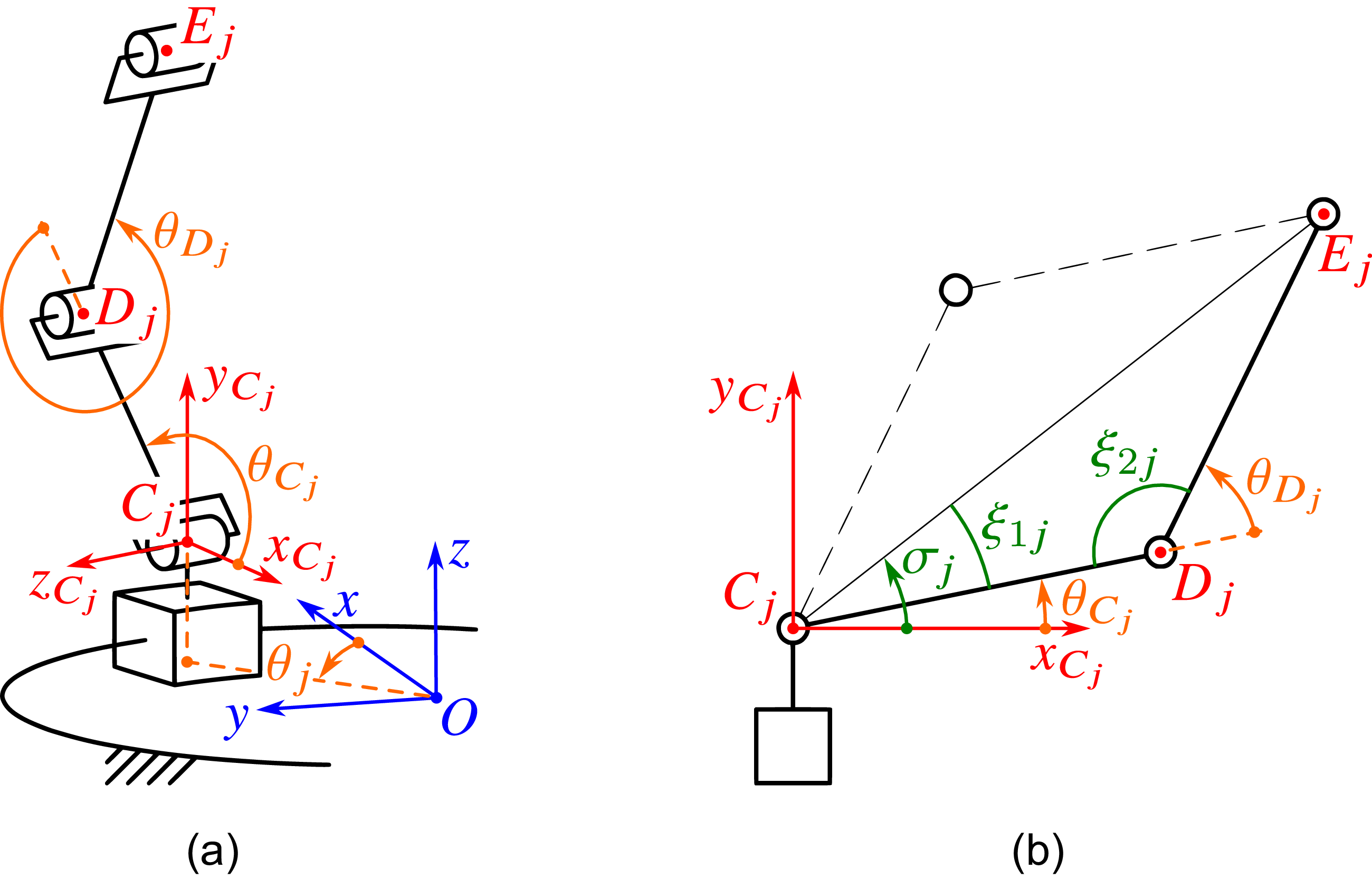
 $E_j$
and belong to the axes of two other revolute joints, as shown in Figs. 2b and 4.
Vectors
 $\mathbf{p}_{C_j}$
and
 $\mathbf{p}_{E_j}$
define the positions of points
 $C_j$
and
 $E_j$
in frame
 $Oxyz$
:
 \begin{align} \mathbf{p}_{C_j} = \begin{bmatrix} R_C\cos (\theta _j) \\[3pt] R_C\sin (\theta _j) \\[3pt] z_C \end{bmatrix}, \qquad \begin{bmatrix} \mathbf{p}_{E_j} \\[3pt] 1 \end{bmatrix} = \mathbf{T}_2 \begin{bmatrix} \mathbf{r}_{E_j} \\[3pt] 1 \end{bmatrix}, \end{align}
where
 $\theta _j$
is the carriage angular displacement; parameters
 $R_C$
and
 $z_C$
define the radial and vertical position of point
 $C_j$
in frame
 $Oxyz$
, and we assume these parameters are identical for each branch; vector
 $\mathbf{r}_{E_j}$
defines the coordinates of point
 $E_j$
in frame
 $O_2x_2y_2z_2$
. Parameters
 $R_C$
,
 $z_C$
, and
 $\mathbf{r}_{E_j}$
have constant values that depend on the robot geometry.
Rotational angles in the joints of the
 $j$
-th lateral branch of the lower module: (a) location of frame
 $C_jx_{C_j}y_{C_j}z_{C_j}$
; (b) planar view of the
 $j$
-th branch.

Points
 $C_j$
and
 $E_j$
belong to the same vertical plane; therefore, we can compute angle
 $\theta _j$
as follows:
 \begin{align} \theta _j = \textrm {atan2}(y_{E_j}, x_{E_j}), \end{align}
where
 $x_{E_j}$
and
 $y_{E_j}$
are the first two components of vector
 $\mathbf{p}_{E_j}$
.
To avoid the collision of the carriages, we should limit angles
 $\theta _j$
. Let
 $\theta _{\mathrm{min}} \gt 0$
be the minimum angular distance between the carriages, which is defined by the robot design. Since the image of the
 $\textrm {atan2}$
function in Eq. (21) is
 $[\! -\pi , \pi ]$
, the following inequalities ensure that the carriages do not collide:
 \begin{align} \theta _{\mathrm{min}} \leq |\theta _1 - \theta _2| \leq 2\pi - \theta _{\mathrm{min}}. \end{align}
Next, we analyze the constraints in two revolute joints, whose axes pass through points
 $C_j$
and
 $D_j$
. Let
 $\theta _{C_j}$
and
 $\theta _{D_j}$
be the rotational angles in these joints (Fig. 4a). To find these angles, we first introduce reference frame
 $C_jx_{C_j}y_{C_j}z_{C_j}$
attached to the
 $j$
-th carriage. Its axis
 $C_jy_{C_j}$
is parallel to the
 $Oz$
axis, and axis
 $C_jx_{C_j}$
is opposite to the
 $Ox$
axis when
 $\theta _j = 0$
. Rotation matrix
 $\mathbf{R}_{C_j}$
defines the orientation of this frame relative to
 $Oxyz$
and can be written as follows:
 \begin{align} \mathbf{R}_{C_j} = \begin{bmatrix} -\mathbf{R}_z(\theta _j)\hat {\mathbf x} &\quad \hat {\mathbf z} &\quad \hat {\mathbf z} \times \left (\mathbf{R}_z(\theta _j)\hat {\mathbf x}\right ) \end{bmatrix} = \begin{bmatrix} -\cos (\theta _j) &\quad 0 &\quad -\sin (\theta _j) \\[3pt] -\sin (\theta _j) &\quad 0 &\quad \phantom {-}\cos (\theta _j) \\[3pt] 0 &\quad 1 &\quad 0\end{bmatrix}, \end{align}
and transformation matrix
 $\mathbf{T}_{C_j}$
between frames
 $C_jx_{C_j}y_{C_j}z_{C_j}$
and
 $Oxyz$
has the following form:
 \begin{align} \mathbf{T}_{C_j} = \begin{bmatrix} \mathbf{R}_{C_j} &\quad \mathbf{p}_{C_j} \\[3pt] \mathbf{0}^{\mathrm{T}} &\quad 1 \end{bmatrix}. \end{align}
Matrix
 $\mathbf{T}_{C_j}$
depends only on angle
 $\theta _j$
, which we computed in Eq. (21). Now, we can consider the 2-DOF planar mechanism located in plane
 $C_jx_{C_j}y_{C_j}$
(Fig. 4b). Let
 $\boldsymbol{\mathrm{\rho }}_{E_j} = [x_j\,y_j]^{\mathrm{T}}$
be the position vector of point
 $E_j$
in frame
 $C_jx_{C_j}y_{C_j}$
. This vector is related to vector
 $\mathbf{p}_{E_j}$
by transformation matrix
 $\mathbf{T}_{C_j}$
:
 \begin{align} \begin{bmatrix} \mathbf{p}_{E_j} \\[3pt] 1 \end{bmatrix} = \mathbf{T}_{C_j} \begin{bmatrix} \boldsymbol{\mathrm{\rho }}_{E_j} \\[3pt] 0 \\[3pt] 1 \end{bmatrix}, \end{align}
from where we determine vector
 $\boldsymbol{\mathrm{\rho }}_{E_j}$
:
 \begin{align} \begin{bmatrix} \boldsymbol{\mathrm{\rho }}_{E_j} \\[3pt] 0 \\[3pt] 1 \end{bmatrix} = \mathbf{T}_{C_j}^{-1} \begin{bmatrix} \mathbf{p}_{E_j} \\[3pt] 1 \end{bmatrix} = \begin{bmatrix} \mathbf{R}_{C_j}^{\mathrm{T}} & -\mathbf{R}_{C_j}^{\mathrm{T}} \mathbf{p}_{C_j} \\[3pt] \mathbf{0}^{\mathrm{T}} & 1 \end{bmatrix} \begin{bmatrix} \mathbf{p}_{E_j} \\[3pt] 1 \end{bmatrix}. \end{align}
To compute angles
 $\theta _{C_j}$
and
 $\theta _{D_j}$
, we follow the approach from [Reference Lynch and Park51, sect. 6] and introduce three auxiliary angles,
 $\sigma _j$
,
 $\xi _{1j}$
, and
 $\xi _{2j}$
(Fig. 4b), which can be found from the following expressions:
 \begin{align} \sigma _j = \textrm {atan2}(y_j, x_j), \;\; \xi _{1j} = \textrm {acos}\left (\frac {\|\boldsymbol{\mathrm{\rho }}_{E_j}\|^2 + l_{CD}^2 - l_{DE}^2}{2\|\boldsymbol{\mathrm{\rho }}_{E_j}\|l_{CD}}\right ), \;\; \xi _{2j} = \textrm {acos}\left (\frac {l_{CD}^2 + l_{DE}^2 - \|\boldsymbol{\mathrm{\rho }}_{E_j}\|^2}{2l_{CD}l_{DE}}\right ), \end{align}
where
 $l_{CD}$
and
 $l_{DE}$
are the lengths of links
 $C_jD_j$
and
 $D_jE_j$
, respectively, which we assume identical for each branch.
Using these angles, we determine two sets of solutions for angles
 $\theta _{C_j}$
and
 $\theta _{D_j}$
:
 \begin{align} \begin{aligned} \theta _{C_j} &= \sigma _j - \xi _{1j}, \\ \theta _{D_j} &= \pi - \xi _{2j}, \end{aligned}\qquad \text{and}\qquad \begin{aligned} \theta _{C_j} &= \sigma _j + \xi _{1j}, \\ \theta _{D_j} &= \xi _{2j} - \pi . \end{aligned} \end{align}
The first solution set matches the “elbow-down” case when
 $\theta _{D_j} \gt 0$
; the second solution set matches the “elbow-up” case when
 $\theta _{D_j} \lt 0$
. We choose the second set according to the lower module design (Fig. 1). This design imposes the following constraints on angles
 $\theta _{C_j}$
and
 $\theta _{D_j}$
:
 \begin{align} \theta _{C\,\mathrm{min}} \leq \theta _{C_j} \leq \theta _{C\,\mathrm{max}}, \qquad \theta _{D\,\mathrm{min}} \leq \theta _{D_j} \leq \theta _{D\,\mathrm{max}}, \end{align}
where
 $\theta _{C\,\mathrm{min}}$
,
 $\theta _{D\,\mathrm{min}}$
,
 $\theta _{C\,\mathrm{max}}$
, and
 $\theta _{D\,\mathrm{max}}$
are the minimum and maximum values of angles
 $\theta _{C_j}$
and
 $\theta _{D_j}$
, and we assume the minimum and maximum values are identical for each branch.
Rotation in the revolute joint between the coupler and the moving platform is not constrained according to the robot design. Thus, it remains to check the rotational angle
 $\theta _{E_j}$
in the revolute joint whose axis passes through point
 $E_j$
. We measure this angle as the angle between two unit vectors,
 $\hat {\mathbf u}_j$
and
 $\hat {\mathbf v}_j$
, directed along line
 $D_jE_j$
and the axis of the platform revolute joint, respectively (Fig. 5). We compute these unit vectors using the following expressions:
 \begin{align} \hat {\mathbf u}_j = \frac {\mathbf{p}_{E_j} - \mathbf{p}_{D_j}}{l_{DE}}, \qquad \begin{bmatrix} \hat {\mathbf v}_j \\[3pt] 0 \end{bmatrix} = \mathbf{T}_2 \begin{bmatrix} \hat {\mathbf e}_j \\[3pt] 0 \end{bmatrix}, \end{align}
where
 $\mathbf{p}_{D_j}$
is the position vector of point
 $D_j$
in frame
 $Oxyz$
;
 $\hat {\mathbf e}_j$
is a unit vector along the axis of the platform revolute joint, expressed in frame
 $O_2x_2y_2z_2$
. Vector
 $\hat {\mathbf e}_j$
is constant and defined by the geometry of the lower module. Vector
 $\mathbf{p}_{D_j}$
can be computed similarly to Eq. (25), where we replace vector
 $\boldsymbol{\mathrm{\rho }}_{E_j}$
with vector
 $\boldsymbol{\mathrm{\rho }}_{D_j} = [l_{CD}\cos (\theta _{C_j})\;\;l_{CD}\sin (\theta _{C_j})]^{\mathrm{T}}$
.
Measuring angle
 $\theta _{E_j}$
: (a) vectors
 $\mathbf{k}_j$
and
 $\hat {\mathbf t}_j$
have the same directions; (a) vectors
 $\mathbf{k}_j$
and
 $\hat {\mathbf t}_j$
have opposite directions.

To set the constraints on angle
 $\theta _{E_j}$
correctly, we must ensure that it is measured in the same sense, disregarding the directions of vectors
 $\hat {\mathbf u}_j$
and
 $\hat {\mathbf v}_j$
. For this purpose, we introduce two auxiliary vectors. The first one is
 $\mathbf{k}_j = \hat {\mathbf u}_j \times \hat {\mathbf v}_j$
, which is orthogonal to both vectors
 $\hat {\mathbf u}_j$
and
 $\hat {\mathbf v}_j$
. The second auxiliary vector is
 $\hat {\mathbf t}_j$
parallel to the
 $C_jz_j$
axis and equal to the third column of rotation matrix
 $\mathbf{R}_{C_j}$
in Eq. (23) (Fig. 5). Using these vectors, we can compute angle
 $\theta _{E_j}$
as follows:
 \begin{align} \theta _{E_j} = \begin{cases} \textrm {acos}(\hat {\mathbf u}_j \cdot \hat {\mathbf v}_j), & \text{if}\quad \mathbf{k}_j \cdot \hat {\mathbf t}_j \geq 0, \\[3pt] 2\pi - \textrm {acos}(\hat {\mathbf u}_j \cdot \hat {\mathbf v}_j), & \text{if}\quad \mathbf{k}_j \cdot \hat {\mathbf t}_j \lt 0. \end{cases} \end{align}
In the first case, vectors
 $\mathbf{k}_j$
and
 $\hat {\mathbf t}_j$
have the same directions, and angle
 $\theta _{E_j} \in [0^\circ , 180^\circ ]$
(Fig. 5a). In the second case, vectors
 $\mathbf{k}_j$
and
 $\hat {\mathbf t}_j$
have opposite directions, and angle
 $\theta _{E_j} \in (180^\circ , 360^\circ )$
(Fig. 5b). We can now define the constraints on angle
 $\theta _{E_j}$
:
 \begin{align} \theta _{E\,\mathrm{min}} \leq \theta _{E_j} \leq \theta _{E\,\mathrm{max}}, \end{align}
where
 $\theta _{E\,\mathrm{min}}$
and
 $\theta _{E\,\mathrm{max}}$
are the minimum and maximum values of angle
 $\theta _{E_j}$
, and we assume the minimum and maximum values are identical for each branch. This concludes the analysis of the mechanical constraints of the lower module.
3.4. Interference between the upper and lower modules
Satisfying the mechanical constraints considered in Sections 3.2 and 3.3 does not guarantee that the upper and lower modules will not interfere with each other. This interference includes collisions between the links of the modules. It affects the workspace of the hybrid robot and should be checked for correct workspace evaluation.
The collision detection problem of the robot links relates directly to analyzing collisions between the rigid bodies representing these links. There are various techniques developed to solve this problem [Reference Jiménez, Thomas and Torras52, Reference Kockara, Halic, Iqbal, Bayrak and Rowe53]. In this paper, we apply the familiar Gilbert–Johnson–Keerthi (GJK) algorithm [Reference Gilbert, Johnson and Keerthi54]. This computationally efficient algorithm allows us to find the distance between convex bodies and, therefore, to check whether they collide or not. The major idea of the GJK algorithm relies on computing the Minkowski difference of two convex subsets of the Euclidean space and evaluating support functions over this difference – we omit the mathematical foundations here, which can be found in the original paper and elsewhere [Reference Van den Bergen55–Reference Montaut, Lidec, Petrik, Sivic and Carpentier57]. Next, we show how to adapt this algorithm to the considered hybrid robot.
According to the robot design (Fig. 1), its upper moving platform should operate above the lower moving platform. Therefore, we consider the following collisions, which are possible between the links of the modules (Fig. 6a):
-
1. Collision between the upper platform and the lower platform.
-
2. Collision between the upper platform and the couplers of the lower module.
-
3. Collision between the upper platform and the upper bars of the lower module.
Collision analysis of the upper and lower modules: (a) convex bodies enveloping the links that can collide; (b) parallelepiped around the upper platform; (c) cylinder around the lower platform; (d) cylinder around the
 $j$
-th coupler; (e) parallelepiped around the
 $j$
-th upper bar.

In this paper, we follow the original GJK algorithm [Reference Gilbert, Johnson and Keerthi54], where the analyzed rigid bodies are not arbitrary convex objects but convex polytopes. Thus, we should represent each link mentioned above as a convex polytope. The following sections describe this representation.
3.4.1. Upper platform
For the upper platform, we define a rectangular parallelepiped that envelops the moving platform and its spherical joints (Fig. 6b). The parallelepiped is determined by the coordinates of its vertices. Let
 $M_0$
be the parallelepiped center and
 $M_k$
,
 $k = 1, \ldots , 8$
, be its vertices, where
 $M_1, \ldots , M_4$
and
 $M_5, \ldots , M_8$
correspond to the top and bottom parallelepiped faces, respectively. We can write coordinates
 $\mathbf{r}_{M_k}$
of these points in frame
 $O_1x_1y_1z_1$
:
 \begin{align} \mathbf{r}_{M_k} = \mathbf{r}_{M_0} + \frac {1}{2}\begin{bmatrix} \varepsilon _k L \\ \delta _k W \\ \zeta _k H \end{bmatrix}, \end{align}
 \begin{align*} \varepsilon _k = \begin{cases} \phantom {-}1, & \text{if}\quad k = 1, 2, 5, 6, \\ -1, & \text{if}\quad k = 3, 4, 7, 8, \end{cases}\quad \delta _k = \begin{cases} \phantom {-}1, & \text{if}\quad k = 1, 4, 5, 8, \\ -1, & \text{if}\quad k = 2, 3, 6, 7, \end{cases}\quad \zeta _k = \begin{cases} \phantom {-}1, & \text{if}\quad k = 1, 2, 3, 4, \\ -1, & \text{if}\quad k = 5, 6, 7, 8, \end{cases} \end{align*}
where
 $\mathbf{r}_{M_0}$
is the position vector of point
 $M_0$
in frame
 $O_1x_1y_1z_1$
;
 $L$
,
 $W$
, and
 $H$
are the length, width, and height of the parallelepiped. All these parameters have constant values depending on the robot design.
3.4.2. Lower platform
We represent the lower moving platform as a right circular cylinder with radius
 $R$
and height
 $S$
(Fig. 6c). To convert the cylinder into a convex polytope, we sample each circular boundary into
 $N$
points. Let
 $P_0$
be the center of the top cylinder face and
 $P_k$
,
 $k = 1, \ldots , 2N$
, be the sample points, where
 $P_1, \ldots , P_N$
and
 $P_{N + 1}, \ldots , P_{2N}$
correspond to the top and bottom cylinder faces, respectively. We can write coordinates
 $\mathbf{r}_{P_k}$
of these points in frame
 $O_2x_2y_2z_2$
:
 \begin{align} \mathbf{r}_{P_k} = \begin{cases} \mathbf{r}_{P_0} + \begin{bmatrix} R \cos (2\pi (k - 1) / N) \\ R \sin (2\pi (k - 1) / N) \\ 0 \end{bmatrix}, & \text{if}\quad k = 1, \ldots , N, \\ \mathbf{r}_{P_{k - N}} - S\hat {\mathbf z}, & \text{if}\quad k = N + 1, \ldots , 2N, \end{cases} \end{align}
where
 $\mathbf{r}_{P_0}$
is the position vector of point
 $P_0$
in frame
 $O_2x_2y_2z_2$
. Parameters
 $R$
,
 $S$
, and
 $\mathbf{r}_{P_0}$
depend on the platform design and have known and constant values.
3.4.3. Couplers
We also use a right circular cylinder to represent each coupler (Fig. 6d). According to the robot design and Section 3.3, the axis of the
 $j$
-th cylinder,
 $j = 1, 2$
, passes through point
 $E_j$
with coordinates
 $\mathbf{r}_{E_j}$
, and it is directed along vector
 $\hat {\mathbf e}_j$
(in frame
 $O_2x_2y_2z_2$
). Let
 $r$
be the cylinder radius and
 $s_1$
and
 $s_2$
be the distances from point
 $E_j$
to the top and bottom cylinder faces, respectively. Because the cylinder is symmetrical above its axis, we can ignore the coupler rotation relative to the moving platform. Therefore, parameters
 $\mathbf{r}_{E_j}$
,
 $\hat {\mathbf e}_j$
,
 $r$
,
 $s_1$
, and
 $s_2$
fully define the cylinder geometry in frame
 $O_2x_2y_2z_2$
. All these parameters have known values depending on the robot design.
To convert the cylinder into a convex polytope, we follow the same approach and sample each circular boundary into
 $n$
points. Let
 $U_{j, k}$
,
 $k = 1, \ldots , 2n$
, be the sample points, where
 $U_{j, 1}, \ldots , U_{j, n}$
and
 $U_{j, n + 1}, \ldots , U_{j, 2n}$
correspond to the top and bottom faces of the
 $j$
-th cylinder, respectively. These points have coordinates
 $\mathbf{r}_{U_{j, k}}$
in frame
 $O_2x_2y_2z_2$
:
 \begin{align} \mathbf{r}_{U_{j, k}} = \begin{cases} \mathbf{r}_{E_j} + s_1\hat {\mathbf e}_j + r (\! \cos (2\pi (k - 1) / n)\hat {\mathbf a}_j + \sin (2\pi (k - 1) / n)\hat {\mathbf b}_j), & \text{if}\quad k = 1, \ldots , n, \\[3pt] \mathbf{r}_{U_{j, k - n}} - (s_1 + s_2)\hat {\mathbf e}_j, & \text{if}\quad k = n + 1, \ldots , 2n, \end{cases} \end{align}
where
 $\hat {\mathbf a}_j$
and
 $\hat {\mathbf b}_j$
are two orthonormal vectors orthogonal to vector
 $\hat {\mathbf e}_j$
, which can be found as follows:
 \begin{align} \textrm {span}\big (\{\hat {\mathbf a}_j, \hat {\mathbf b}_j\}\big ) = \textrm {null}\big (\hat {\mathbf e}_j^{\mathrm{T}}\big ). \end{align}
Equations (33)–(35) are sufficient to analyze the collisions between the upper platform, the lower platform, and the couplers. For this purpose, we just need to transform coordinates
 $\mathbf{r}_{M_k}$
from frame
 $O_1x_1y_1z_1$
to frame
 $O_2x_2y_2z_2$
using transformation matrix
 $\mathbf{T}$
. Thus, these collisions are analyzed in frame
 $O_2x_2y_2z_2$
with no need to transform coordinates
 $\mathbf{r}_{P_k}$
and
 $\mathbf{r}_{U_{j, k}}$
.
3.4.4. Upper bars
Finally, we use a rectangular parallelepiped to represent the geometry of each upper bar (Fig. 6e). Let
 $V_{j, k}$
,
 $k = 1, \ldots , 8$
, be its vertices, where
 $V_{j, 1}, \ldots , V_{j, 4}$
and
 $V_{j, 5}, \ldots , V_{j, 8}$
correspond to the top and bottom faces of the
 $j$
-th parallelepiped, respectively (
 $j = 1, 2$
). To find the coordinates of these vertices, we first introduce reference frame
 $D_jx_{D_j}y_{D_j}z_{D_j}$
attached to the
 $j$
-th upper bar. Its
 $D_jx_{D_j}$
axis coincides with line
 $D_jE_j$
, and the
 $D_jz_{D_j}$
axis has the same direction as axis
 $C_jz_{C_j}$
. We can write coordinates
 $\mathbf{r}_{V_{j, k}}$
of the parallelepiped vertices in frame
 $D_jx_{D_j}y_{D_j}z_{D_j}$
:
 \begin{align} \mathbf{r}_{V_{j, k}} = \begin{cases} \begin{bmatrix} -d \\ \zeta _k h/2 \\ \varepsilon _k w/2 \end{bmatrix}, & \text{if}\quad k = 1, 4, 5, 8, \\ \mathbf{r}_{V_{j, k - 4}} + l \hat {\mathbf x}, & \text{if}\quad k = 2, 3, 6, 7, \\ \end{cases} \end{align}
where
 $l$
,
 $w$
, and
 $h$
are the length, width, and height of the parallelepiped;
 $d$
is a distance from point
 $D_j$
to the left face of the parallelepiped;
 $\zeta _k$
and
 $\varepsilon _k$
have the same meaning as in Eq. (33). All these parameters have constant values depending on the robot design.
To analyze the collision between the upper platform and the
 $j$
-th upper bar, we should express coordinates
 $\mathbf{r}_{M_k}$
and
 $\mathbf{r}_{V_{j, k}}$
in the same reference frame, for example, in base frame
 $Oxyz$
. Let
 $\mathbf{p}_{M_k}$
and
 $\mathbf{p}_{V_{j, k}}$
denote these coordinates in this frame. We can compute these coordinates using transformation matrices
 $\mathbf{T}_1$
and
 $\mathbf{T}_{D_j}$
:
 \begin{align} \begin{bmatrix} \mathbf{p}_{M_k} \\[3pt] 1 \end{bmatrix} = \mathbf{T}_1 \begin{bmatrix} \mathbf{r}_{M_k} \\[3pt] 1 \end{bmatrix}, \qquad \begin{bmatrix} \mathbf{p}_{V_{j, k}} \\[3pt] 1 \end{bmatrix} = \mathbf{T}_{D_j} \begin{bmatrix} \mathbf{r}_{V_{j, k}} \\[3pt] 1 \end{bmatrix}, \end{align}
where
 $\mathbf{T}_{D_j}$
is a transformation matrix between frames
 $D_jx_{D_j}y_{D_j}z_{D_j}$
and
 $Oxyz$
:
 \begin{align} \mathbf{T}_{D_j} = \mathbf{T}_{C_j} \begin{bmatrix} \mathbf{R}_z(\theta _{C_j}) & \mathbf{0} \\[3pt] \mathbf{0}^{\mathrm{T}} & 1 \end{bmatrix} \begin{bmatrix} \mathbf{I}_3 & l_{DE}\hat {\mathbf x} \\[3pt] \mathbf{0}^{\mathrm{T}} & 1 \end{bmatrix} \begin{bmatrix} \mathbf{R}_z(\theta _{D_j}) & \mathbf{0} \\[3pt] \mathbf{0}^{\mathrm{T}} & 1 \end{bmatrix}. \end{align}
Thus, we have represented all the considered links as convex polytopes and derived the explicit expressions for the coordinates of their vertices. This information is sufficient to implement the GJK algorithm and check if the links collide. This concludes the workspace analysis of the hybrid robot. The next section considers numerical examples.
4. Examples
In this section, we consider two types of workspaces common to robotic systems [Reference Merlet58, ch. 7]:
-
1. Translation workspace – the set of reachable positions of the upper moving platform relative to the lower moving platform when their relative orientation is fixed. In other words, we determine the set of position vectors
$\mathbf{p}$
when rotation matrix
$\mathbf{R}$
is constant. -
2. Orientation workspace – the set of reachable orientations of the upper moving platform relative to the lower moving platform when their relative position is fixed. In other words, we determine the set of rotation matrices
$\mathbf{R}$
when position vector
$\mathbf{p}$
is constant.


To make our analysis and representation of the results clearer, we parameterize rotation matrix
 $\mathbf{R}$
using tilt-and-torsion angles [Reference Bonev and Gosselin50, Reference Bonev, Zlatanov and Gosselin59]:
 \begin{align} \mathbf{R} = \mathbf{R}_z(\psi ) \mathbf{R}_y(\theta ) \mathbf{R}_z(\sigma - \psi ), \end{align}
where
 $\psi$
,
 $\theta$
, and
 $\sigma$
are the azimuth, tilt, and torsion angles, respectively.
Here, angle
 $\theta$
characterizes the tilt of the upper platform relative to the lower one, while angle
 $\psi$
determines the direction of this tilt. Finally, angle
 $\sigma$
describes the self-rotation (torsion). We refer to paper [Reference Bonev, Zlatanov and Gosselin59] for more details about this parameterization and its advantages.
Geometrical parameters of the hybrid robot correspond to its computer model (Fig. 1) and have the following values:
-
• Upper module:
\begin{align*} \boldsymbol{\mathrm{\rho }}_{A_1} = \begin{bmatrix} 256 \\ 0 \end{bmatrix}\text{mm}, \quad \boldsymbol{\mathrm{\rho }}_{A_2} = \begin{bmatrix} 50 \\ -256 \end{bmatrix}\text{mm}, \quad \boldsymbol{\mathrm{\rho }}_{A_3} = \begin{bmatrix} -50 \\ -256 \end{bmatrix}\text{mm}, \quad \boldsymbol{\mathrm{\rho }}_{A_4} = \begin{bmatrix} -256 \\ 0 \end{bmatrix}\text{mm}, \end{align*}
\begin{gather*} \!\! \mathbf{r}_{B_1} = \begin{bmatrix} 84.5 \\ 0 \\ -6 \end{bmatrix}\text{mm}, \; \mathbf{r}_{B_2} = \begin{bmatrix} 50 \\ -84.5 \\ -6 \end{bmatrix}\text{mm}, \; \mathbf{r}_{B_3} = \begin{bmatrix} -50 \\ -84.5 \\ -6 \end{bmatrix}\text{mm}, \; \mathbf{r}_{B_4} = \begin{bmatrix} -84.5 \\ 0 \\ -6 \end{bmatrix}\text{mm}, \\ l_{AB} = 379\,\text{mm}. \end{gather*}
-
• Lower module:
\begin{gather*} l_{OF} = 204\,\text{mm}, \quad l_{FO_2} = 57.7\,\text{mm}, \quad R_C = 183.7\,\text{mm}, \quad z_C = 100.3\,\text{mm}, \quad l_{CD} = l_{DE} = 150\,\text{mm}, \\ \mathbf{r}_{E_1} = \begin{bmatrix} 100.5 \\ 0 \\ 5.9 \end{bmatrix}\text{mm}, \quad \mathbf{r}_{E_2} = \begin{bmatrix} -100.5 \\ 0 \\ 5.9 \end{bmatrix}\text{mm}, \quad \hat {\mathbf e}_1 = \mathbf{R}_y(\! -32.2^\circ )\hat {\mathbf x}, \quad \hat {\mathbf e}_2 = \mathbf{R}_y(212.2^\circ )\hat {\mathbf x}. \end{gather*}


Joints constraints of the lower and upper modules are listed below:
-
• Upper module:
\begin{align*} h_{\mathrm{min}} = 490\,\text{mm}, \quad h_{\mathrm{max}} = 930\,\text{mm}, \\[-33pt] \end{align*}
\begin{align*} \psi _{A\,\mathrm{min}} = \psi _{B\,\mathrm{min}} = 0^\circ , \; \psi _{A\,\mathrm{max}} = \psi _{B\,\mathrm{max}} = 180^\circ , \; \eta _{A\,\mathrm{min}} = \eta _{B\,\mathrm{min}} = -20^\circ , \; \eta _{A\,\mathrm{max}} = \eta _{B\,\mathrm{max}} = 20^\circ . \\[-30pt] \end{align*}
-
• Lower module:
\begin{align*} \beta _{\mathrm{min}} = -70^\circ , \quad \beta _{\mathrm{max}} = 70^\circ , \quad \theta _{\mathrm{min}} = 8^\circ , \\[-32pt] \end{align*}
\begin{align*} \theta _{C\,\mathrm{min}} = -5^\circ , \; \theta _{C\,\mathrm{max}} = 180^\circ , \; \theta _{D\,\mathrm{min}} = -160^\circ , \; \theta _{D\,\mathrm{max}} = 160^\circ , \; \theta _{E\,\mathrm{min}} = 20^\circ , \; \theta _{E\,\mathrm{max}} = 340^\circ . \\[-32pt] \end{align*}


Finally, the parameters of the links for which we analyze the collisions are the following:
-
• Upper moving platform:
\begin{equation*} \mathbf{r}_{M_0} = \begin{bmatrix} 0 \\ -12.3 \\ -5 \end{bmatrix}\text{mm}, \quad L = 189\,\text{mm}, \quad W = 164\,\text{mm}, \quad H = 22\,\text{mm}. \end{equation*}
-
• Lower moving platform:
\begin{equation*} \mathbf{r}_{P_0} = \begin{bmatrix} 0 \\ 0 \\ 0 \end{bmatrix}\text{mm}, \quad R = 78.7\,\text{mm}, \quad S = 13.1\,\text{mm}, \quad N = 12. \end{equation*}
-
• Couplers:
\begin{equation*} r = 10.2\,\text{mm}, \quad s_1 = 0\,\text{mm}, \quad s_2 = 28.1\,\text{mm}, \quad n = 12. \end{equation*}
-
• Upper bars:
\begin{equation*} d = 7.9\,\text{mm}, \quad l = 2d + l_{DE} = 165.8\,\text{mm}, \quad w = 28.1\,\text{mm}, \quad h = 15.7\,\text{mm}. \end{equation*}


All subsequent simulations have been performed in Julia [Reference Bezanson, Edelman, Karpinski and Shah60]: the source code of the developed program is available at the link at the end of the paper. The GJK algorithm has been implemented using Julia package EnhancedGJK.jl.Footnote 1
In the simulations, we first checked the joint constraints and then analyzed the link interference. The figures in the following sections present the results. In all the figures, green areas represent the resulting workspace that satisfies all constraints, while red areas indicate workspace points that meet the joint constraints but violate the collision constraints.
4.1. Translation workspace
To analyze the translation workspace, we sample the
 $x$
,
 $y$
, and
 $z$
components of position vector
 $\mathbf{p}$
in ranges
 $[\! -200, 200]$
mm,
 $[\! -250, 250]$
mm, and
 $[0, 400]$
mm, respectively, with a step size of 5 mm for each component. In the first example, we consider the zero relative orientation of the modules:
 $\psi = \theta = \sigma = 0^\circ$
. Figure 7 shows the results. The translation workspace has a symmetrical shape that meets the symmetrical design of the robot. The workspace envelops the rectangular parallelepiped with the sides of 250 mm, 250 mm, and 300 mm along the
 $x$
,
 $y$
, and
 $z$
directions, respectively. Note how the lower part of the analyzed space (
 $z \lt 30$
mm) is discarded because of the link interference.
Translation workspace and its projections for
 $\psi = \theta = \sigma = 0^\circ$
.

The second example considers the tilted configuration:
 $\psi = 0^\circ$
,
 $\theta = -30^\circ$
,
 $\sigma = 0^\circ$
. In this case, the upper platform tilts about the
 $O_2y_2$
axis, while the lower platform keeps zero orientation according to the robot design. Figure 8 shows that the workspace has been reduced by more than a half, and the points with
 $x \gt 0$
mm are unreachable with this orientation. The points with
 $z \lt 75$
mm are also unreachable because of the link interference between the modules.
Translation workspace and its projections for
 $\psi = 0^\circ$
,
 $\theta = -30^\circ$
,
 $\sigma = 0^\circ$
.

In the third example, we consider the same tilt angle but alter the direction of the tilt axis:
 $\psi = 30^\circ$
,
 $\theta = -30^\circ$
,
 $\sigma = 0^\circ$
. Now, both the upper and lower moving platforms should rotate to achieve this relative orientation. The results in Fig. 9 look similar to Fig. 8, but the whole workspace becomes inclined, reflecting the changes of the tilt axis.
Translation workspace and its projections for
 $\psi = 30^\circ$
,
 $\theta = -30^\circ$
,
 $\sigma = 0^\circ$
.

Finally, we add the non-zero torsion to the previous example:
 $\psi = 30^\circ$
,
 $\theta = -30^\circ$
,
 $\sigma = 45^\circ$
. Figure 10 shows the computed translation workspace. Although the workspace still has a large size in the
 $z$
direction (about 300 mm), it has an irregular shape and is quite limited in the
 $x$
and
 $y$
directions, while the points with
 $x \gt 0$
mm remain unreachable.
Translation workspace and its projections for
 $\psi = 30^\circ$
,
 $\theta = -30^\circ$
,
 $\sigma = 45^\circ$
.

4.2. Orientation workspace
To analyze the orientation workspace, we represent it in a polar coordinate system similar to paper [Reference Bonev and Gosselin50]. For each considered value of torsion angle
 $\sigma$
, we make a planar plot in polar axes where the radial coordinate is proportional to tilt angle
 $\theta$
and the angular coordinate is equal to azimuth angle
 $\psi$
.
We specify all these angular parameters as follows. First, we sample tilt angle
 $\theta$
in range
 $[0^\circ , 90^\circ ]$
with a step of
 $2.5^\circ$
. Then, we sample azimuth angle
 $\psi$
in range
 $[0^\circ , 360^\circ )$
, and number
 $p$
of its samples depends on the value of angle
 $\theta$
. If
 $\theta = 0^\circ$
, the azimuth angle is not defined, and we set
 $\psi = 0^\circ$
. If
 $\theta \neq 0^\circ$
, we compute number
 $p$
as follows:
 \begin{align} p = p_{\mathrm{max}} \Bigl \lceil \dfrac {\theta }{\theta _{\mathrm{max}}}\Bigr \rceil , \end{align}
where
 $\theta _{\mathrm{max}}$
is the maximum considered value of angle
 $\theta$
, which is equal to
 $90^\circ$
in our examples;
 $p_{\mathrm{max}}$
is a number of samples of angle
 $\psi$
when
 $\theta = \theta _{\mathrm{max}}$
, and we set
 $p_{\mathrm{max}} = 120$
;
 $\lceil *\rceil$
is the ceiling function that gives the lowest integer greater or equal to its argument.
Equation (41) provides us with a uniform sampling of the polar coordinate space and avoids dense sampling near the origin, unlike the regular (independent) sampling of parameters
 $\psi$
and
 $\theta$
. Finally, we consider four different values of torsion angle
 $\sigma$
:
 $0^\circ$
,
 $20^\circ$
,
 $40^\circ$
, and
 $60^\circ$
.
In the first example, we examine the orientation workspace for the point near the geometric center of the translation workspace depicted in Fig. 7:
 $x = y = 0$
mm,
 $z = 150$
mm. Figure 11 illustrates the results. For each value of torsion angle
 $\sigma$
, the upper platform can tilt relative to the lower platform for
 $20^\circ$
in any direction. When azimuth angle
 $\psi$
is near
 $90^\circ$
or
 $270^\circ$
, the upper platform can tilt further: tilt angle
 $\theta$
reaches
 $40^\circ$
and even
 $60^\circ$
with
 $\sigma = 40^\circ$
.
Orientation workspace for
 $x = y = 0$
mm,
 $z = 150$
mm.

The second example considers the orientation workspace for the point at the same height but displaced along the
 $x$
direction:
 $x = 100$
mm,
 $y = 0$
mm,
 $z = 150$
mm. Figure 12 shows that the upper platform can tilt only in a limited sector. For example, if we look at the plots for
 $\sigma = 0^\circ$
and
 $\sigma = 20^\circ$
, we observe that tilt angle
 $\theta$
reaches
 $40^\circ$
but the tilts are possible only for angles
 $\psi$
in a range of about
 $[\! -90^\circ , 90^\circ ]$
. The orientation workspaces decreases as torsion angle
 $\sigma$
takes higher values.
Orientation workspace for
 $x = 100$
mm,
 $y = 0$
mm,
 $z = 150$
mm.

In the third example, we include the same displacement in the
 $y$
direction:
 $x = 100$
mm,
 $y = 100$
mm,
 $z = 150$
mm. Figure 13 shows that the tilt sector (the range of angle
 $\psi$
) decreases even more. The higher the torsion angle, the narrower this sector, but tilt angle
 $\theta$
can reach
 $60^\circ$
for each considered value of angle
 $\sigma$
.
Orientation workspace for
 $x = 100$
mm,
 $y = 100$
mm,
 $z = 150$
mm.

The previous examples analyzed the orientation workspace when the upper platform stayed beyond the lower one, such that the links of the upper and lower modules did not interfere. In the fourth example, we consider the case when the platforms are near each other, and the height of the examined point is twice lower:
 $x = y = 0$
mm,
 $z = 75$
mm. Figure 14 illustrates the obtained orientation workspace. The regions of the link interference (the red areas in each plot) constrain the tilt angle: angle
 $\theta$
is limited by
 $40^\circ$
, but it could reach
 $60^\circ$
and even higher values if we ignore the link collisions between the modules.
Orientation workspace for
 $x = y = 0$
mm,
 $z = 75$
mm.

4.3. CAD simulations
To validate the theoretical results obtained in the preceding sections, we performed a series of CAD simulations in the KOMPAS 3D software using the computer model from Fig. 1. For this purpose, we selected several points in the workspaces presented in Figs. 7–14. Each point corresponds to a specific relative configuration of the modules, and we checked if the robot could reach the considered configuration. Note that in the CAD software, it is challenging to accurately place the moving platforms relative to each other, especially when they are tilted. To overcome this issue, we first solved the inverse kinematic problem for each selected point and then positioned the carriages of the modules according to the obtained solution. This approach ensures that the relative configuration of the moving platforms meets the selected point.
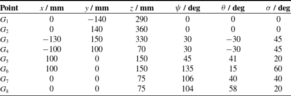
This section illustrates the results for eight points
 $G_1, \ldots , G_8$
, and Table I presents the values of position parameters
 $x$
,
 $y$
, and
 $z$
and rotation parameters
 $\psi$
,
 $\theta$
, and
 $\sigma$
corresponding to these points. The considered points are selected in the following way:
-
• Points
$G_1$
and
$G_2$
belong to the top boundary surface of the translation workspace in Fig. 7. -
• Points
$G_3$
and
$G_4$
belong to the front boundary edge of the translation workspace in Fig. 10. -
• Points
$G_5$
and
$G_6$
belong to the boundaries of the orientation workspace in Fig. 12. -
• Points
$G_7$
and
$G_8$
belong to the boundaries of the orientation workspace in Fig. 14.


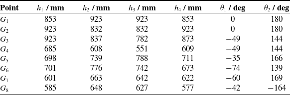
Table II shows the solution to the inverse kinematic problem for each considered point. We used these data to position the carriages in the developed computer model of the robot. For each point, the obtained relative configuration of the modules met the expected one specified in Table I. Figures 15–22 show the 3D view, front view, and side view of the robot in these configurations, where the right lateral branch of the upper module in the side view is hidden for clarity. The red notations in the figures match the preceding sections and indicate the constraints that limit the workspace in the considered configuration.
As we observe from the figures, these are constraints in the spherical joints that limit the workspace in most cases, that is, the constraints on angles
 $\eta _{A_i}$
and
 $\eta _{B_i}$
specified in Eqs. (15) and (18).Footnote
2
In Fig. 15, the carriages of the two central branches of the upper module reach their highest positions, satisfying Eq. (10); a similar situation is observed in Figs. 16 and 17 for the lateral branches. These results correspond to our selection of points
 $G_1$
,
 $G_2$
, and
 $G_3$
on the top surface of the workspace (Figs. 7 and 10). Figures 18, 21, and 22 show that the moving platforms of the modules are about to collide with each other. This situation agrees with the selection of points
 $G_4$
,
 $G_7$
, and
 $G_8$
on the boundaries of the green and red areas in Figs. 10 and 14. It is interesting that the link interference is the only constraint limiting the workspace in Fig. 21: other joint constraints are not violated in this configuration. This result indicates that the link interference of the modules should not be ignored for the correct evaluation of the workspace.
5. Discussion
The methods presented in Sections 3 and 4 allow us to obtain workspaces in the relative motion of two modules. This is a crucial difference from most other papers mentioned in the introduction, where workspaces were considered with respect to the base. On the other hand, analyzing the workspace in the relative motion is more important in practice, for example, in machining, where one module usually displaces the processed part and another module moves the tool. Unlike other methods, the developed techniques allow solving this problem directly without the stage where we need to combine the two workspaces and find their intersection, thereby reducing the computational efforts. Thus, we believe that the proposed methods and obtained results are original and will be valuable for practical applications.
During the workspace analysis, we considered all mechanical constraints existing in the hybrid robot, including the joint constraints and the link interference between the upper and lower modules. Section 4 shows that the link interference significantly affects the workspace and must be included in the workspace analysis. For example, if we ignored the link interference in Fig. 14, we would get the higher tilt angles of the upper moving platform relative to the lower one. These results, however, would be incorrect and could lead to collisions and potential damage of the robot links in real applications.
To analyze these collisions, we applied the GJK algorithm and represented the robot links as convex polytopes. There exist modifications of this algorithm that can deal with general convex objects and rely on optimization techniques [Reference Gilbert and Foo61–Reference Montaut, Lidec, Petrik, Sivic and Carpentier64]. These methods avoid errors caused by polytope approximations, and they can be used to get more accurate results with less computational efforts. Implementing these techniques in workspace analysis looks promising as well.
The order in which we evaluate mechanical constraints also affects computational efforts. In this paper, we first analyzed the joint constraints and then considered the link interference. We applied this order for illustrative purposes to show the parts of the workspace that meet the joint constraints but violate the link interference (Figs. 7–14). Evaluating the joint constraints requires solving the inverse kinematic problem, as discussed in Sections 3.1–3.3. On the other hand, Sections 3.4.1–3.4.3 show that we do not need to solve this problem to analyze the collisions between the upper platform, the lower platform, and the couplers. These collisions depend only on the relative configuration of the platforms (i.e., on transformation matrix
 $\mathbf{T}$
), which is the predefined parameter for the applied discretization approach of the workspace analysis. Thus, by changing the order of constraint evaluation, we can avoid unnecessary computations. In addition, we can ignore the link interference constraint when the upper moving platform is beyond the lower module.
Selected points for CAD simulations.

Solution to the inverse kinematics for the selected points.

Robot configuration corresponding to point
 $G_1$
.

Robot configuration corresponding to point
 $G_2$
.

Robot configuration corresponding to point
 $G_3$
.

Robot configuration corresponding to point
 $G_4$
.

Robot configuration corresponding to point
 $G_5$
.

Robot configuration corresponding to point
 $G_6$
.

Finally, we should note that singular configurations can divide the workspace into several disjoint regions [Reference Kolte, Ramesh and Bandyopadhyay65]. For example, in paper [Reference Laryushkin, Fomin and Antonov37], we performed the standalone singularity analysis of the 4-DOF upper module and showed that it could not bypass the singularity surface with constant tilt angle
 $\varphi$
. The lower module can be used to overcome this problem by adjusting the relative orientation of the moving platforms. At the same time, as we have seen in Section 3.2, there exists at least one singular configuration where the robot loses one rotational DOF in the relative motion, while each module does not meet a singularity. This situation is not typical for conventional parallel or serial robots, which include only a single module [Reference Conconi and Carricato66]. The complete enumeration of these and other singular configurations, as well as estimating the closeness to them [Reference Voglewede and Ebert-Uphoff67, Reference Bu68], requires deriving and analyzing Jacobian matrices, which is beyond this paper and will be the subject of our upcoming studies.
Robot configuration corresponding to point
 $G_7$
.

Robot configuration corresponding to point
 $G_8$
.

6. Conclusion
The paper performed the workspace analysis of the recently proposed hybrid robot with two parallel modules. One module is a 4-DOF Delta-type parallel mechanism with three translational and one rotational DOFs, and the other module is a 2-DOF rotational parallel mechanism with a circular rail. Thus, the robot has six DOFs in the relative motion of its modules.
In this article, we developed the discretization-based approach that allowed computing the workspace in the relative motion of the modules. The approach relies on the inverse kinematics, for which we provided the closed-form solution, and considers constraints in all joints of the robot, as well as the link interference between the modules. To check the collisions between the links, we represented them as convex polytopes and applied the GJK algorithm.
The proposed techniques were implemented to analyze the translation and orientation workspaces of the hybrid robot. We presented four numerical examples for each workspace and various relative configurations of the modules and analyzed eight specific configurations of the robot in CAD software to validate the developed algorithms. The results indicate that the link interference affects the workspace shape and dimensions and cannot be ignored for correct workspace analysis.
The developed methods are not limited to translation and orientation workspaces but can be used to compute other types of workspaces as well. These methods are also applicable to other hybrid robots composed of two modules. In future studies, we will include singular configurations to the workspace analysis and use the obtained results for trajectory planning and optimal design of the robot.
Author contributions
AA and AF conceived and designed the study. KM and AA devised the workspace analysis method and performed simulations in Julia. KM, AF, and AA prepared graphical material and wrote the manuscript. AA and AF supervised the article.
Data availability statement
Julia program that performs the workspace analysis according to the proposed algorithms is available free online at https://doi.org/10.17632/vsvvd83gpy.1.
Funding statement
This research was supported by the Russian Science Foundation under grant no. 22-79-10304, https://rscf.ru/en/project/22-79-10304/.
Competing interests
The authors declare that no conflicts of interest exist.
Ethical approval
Not applicable.