I. INTRODUCTION
During the past decade, the need for high data rate applications and low power consumption for communication and radar systems encouraged the need for the ultra-wideband (UWB) systems. UWB applications have been assigned, by the Federal Communication Commission (FCC), the frequency band of 3.1–10.6 GHz [1]. Antenna requirements for this technology are wide band impedance matching, high efficiency, omnidirectional radiation pattern over the band, and a time response that is capable of supporting narrow pulses that cover the specified band.
The challenges for satisfying these antennas can be summarized as: (1) The trade-off between a good antenna matching with stable pattern and non-degrading antenna efficiency at high UWB frequencies, (2) The antenna time response that make it capable of preserving a narrow time domain pulse (wide spectrum pulse) shape, while going through the terminals of the antennas till reaching the propagation channel. These antennas challenges have to be overcome with simple, low cost, and low profile structure which are preferred for communication antennas.
Focus has been directed toward small printed antennas that can serve in UWB frequencies, while can be easily mounted in the platform of small communications devices, especially the handheld ones. Planar monopole antennas are good candidate for UWB antennas in coplanar waveguide (CPW) and microstrip feeding configurations. Among different monopole shapes, circular monopole disc antennas demonstrate good choice for fulfilling the aforementioned typical UWB antenna requirements [Reference Abdelraheem, Abdalla, Elregily and Mitkees2–Reference Srifi, Podilchak, Essaaidi and Antar9]. Moreover, the ground shaping adaption is additional trail for adapting the radiation pattern [Reference Lu, Huang, Chattha and Cao10]. Also, the trend to obtain compact antennas rather than the large ones has been of great importance, examples on these are [Reference Gopikrishna, Krishna, Anandan, Mohanan and Vasudevan11–Reference Sugitani, Kubota, Toya, Xiao and Kikkawa15].
CPW structures have many attractive features, such as their easy, inexpensive fabrication procedures, and simple series and shunt connections. Also, active elements have a planar structure nature, and hence they can be connected easily to other CPW configurations.
In this paper, a compact CPW feed modified semi-circular monopole antenna is introduced to cover the bandwidth 2.2–10.6 GHz. The main compactness objective of the desired antenna has been achieved by comparing the antenna performance to its complete version typical circular antenna operating at the same bandwidth. In addition to the designed antenna compactness, its radiation pattern and radiation efficiency characteristics were carefully preserved over the band specified by the FCC and extending to the end of the x-band. Moreover, comprehensive frequency and time domain study is introduced based on electromagnetic full wave simulations and experimental measurements to the characteristics of the designed antenna.
The paper is organized as follows: in Section II, the design of the antenna is discussed in details; layout with complete dimensions is presented. Also, the conventional CPW circular monopole analysis is presented for comparison with the proposed antenna. In Section III, fabrication of the proposed antenna is discussed, results for simulated and measured VSWR is presented. Simulated current distribution is extracted to assure stable performance of the antenna over the band. Simulated and measured radiation pattern is presented and compared to confirm the stable performance of the antenna. Simulated radiation efficiency is extracted and figured to assure efficient radiation over the band. In Section IV, the antenna time response was strictly investigated. Experimental setup for measuring antenna transfer function with different antennas orientations was conducted. A first-order Rayleigh pulse was applied to the system transfer function and tested for dispersion at the terminal of the receiving antenna.
II. ANTENNA DESIGN
The design of UWB monopole antennas with good matching properties has several approaches [Reference Volakis16]. One approach is based on perturbing the electromagnetic resonance formed in the antenna structure. This can be achieved, simply, by increasing diffraction edges to broaden the resonance peaks. This approach is limited by the excitation of higher order modes that results in pattern narrowing and multiple radiation lobes. Another approach is based on allowing only one radiation area. This area size is much smaller compared to the wavelength. This can be done by utilization of absorptive loading, or by means of reducing diffraction edges. In practice, this can be accomplished through using smooth rounded edges rather than sharp edges. As a limitation for this type, the antenna gain and pattern are frequency depended. A trade-off between matching from a side, and preserving pattern and gain from the other side, should be considered carefully.
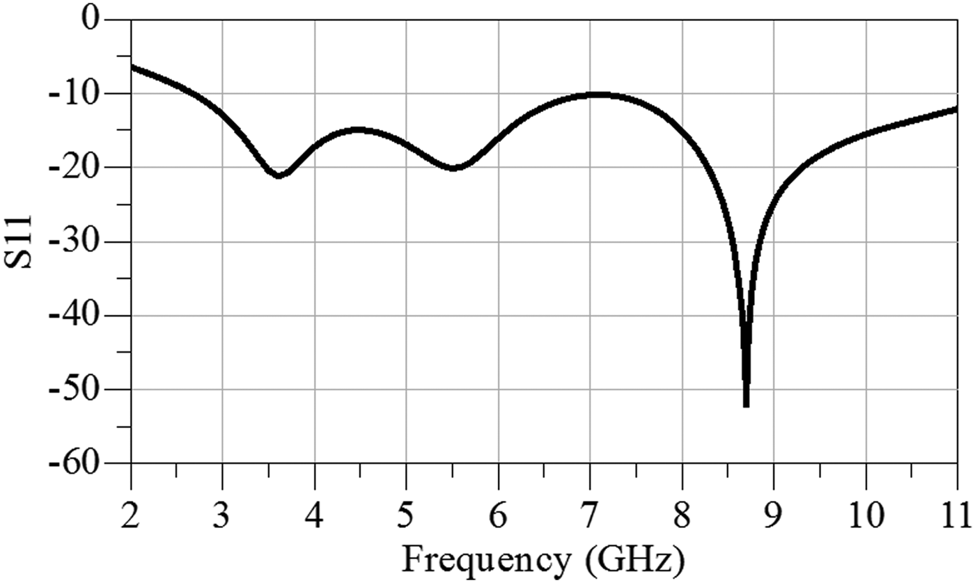
The proposed antenna design has achieved a good compromise between matching on one hand and preserving pattern and radiation efficiency on the other hand. Moreover, the proposed antenna introduced 33.5% size reduction when compared with typical CPW circular monopole antenna. The antenna design started from the typical CPW circular monopole antenna which was deeply investigated and analyzed in [Reference Chen17]. The layout of the typical CPW circular monopole antenna is illustrated in Fig 1(a). This circular monopole antenna has a 50 Ω CPW feeding transmission line with W = 2 mm, width of the centre strip and, G = 0.25 mm, the separation between centre strip and ground planes, on FR-4 substrate (ε r = 4.4 and thickness H = 1.6 mm). A typical CPW circular monopoles presented in [Reference Chen17] introduced matching bandwidth that spans the whole FCC bandwidth assigned for UWB applications (3.5–10.6 GHz) with disc diameters of 0.25λ 1, where λ 1 is the wavelength corresponding to the first resonance frequency (different frequencies for different monopoles). Figure 2 illustrates the simulated reflection coefficient of a typical CPW circular monopole antenna designed on FR-4 substrate (1.6 mm thickness and ε r = 4.4). As can be seen from the figure, the first resonance occurs at 3.6 GHz, indicating a typical CPW circular monopole antenna with disc diameter 0.24λ 1 (20.2 mm). It should be noted here that the typical monopole chosen to have the nearest first resonance frequency as the proposed antenna to build up a reasonable comparison. The first resonance frequency for the proposed antenna is 3.5 GHz.
The layout of a (a) typical circular monopole UWB antenna and (b) the proposed curved half circular monopole UWB antenna.

Full wave simulated results for typical circular monopole antenna.
In order to decrease the size of the circular monopole antenna and keep the smooth rounded diffraction edges of the monopole radiator, adapting the antenna radiator, to be as a curved half monopole antenna with no sharp edges as shown in Fig 1(b), have been suggested. The detailed design was achieved after intense optimizations for the monopole curvature. It is clear that the overall antenna size is (3.4 × 4.3 cm2) introduced compactness features of 33.5% size reduction in comparison with the typical circular antenna.
III. ANTENNA ANALYSIS
A photograph for the fabricated antenna is illustrated in Figs 3(a) and 3(b). As shown in the figure, the whole antenna size is measured by a digital Vernier caliper (4.4 × 3.45 cm2). The antenna configuration fabrication process was carried out by using wet etching of the copper metallization to remove the unwanted masked parts of the metallization on both sides of the employed FR4 substrate.
Photograph of the fabricated UWB antenna measured for (a) width and (b) length, by means of digital Vernier caliper.
A) Antenna matching
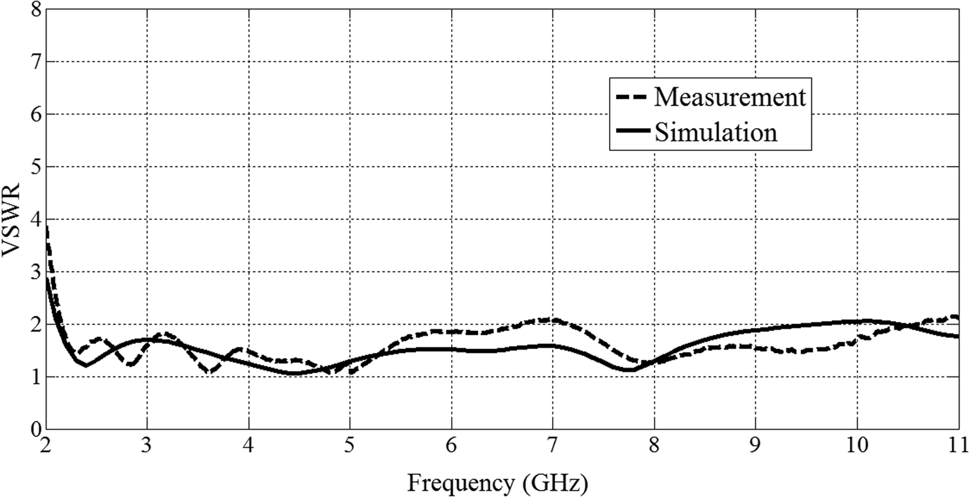
The matching performance of the proposed UWB antenna was investigated through VSWR. This was done by full wave simulation and confirmed by practical measurements. The full wave simulated and measured VSWR for the proposed compact half circular disc monopole antenna are illustrated in Fig 4. It is clear that the simulated and measured VSWR is lower than 2 (approximate −10 dB reflection coefficient) within the frequency band 2.2 GHz up to 10.6 GHz, except for a small peak in the measured VSWR at 7 GHz. This can be referred to fabrication imperfections and the existence of potential reflectors in the measurement environment. Other than the aforementioned mismatch, a good agreement between measured and simulated results is observed.
Measured and simulated VSWR for the proposed antenna.
B) Radiation spatial characteristics
UWB performance is fulfilled if the antenna shows stable characteristics throughout the band of interest. A clue that the antenna will maintain omnidirectional radiation pattern over the entire band may be deduced from the antenna current distributions at different frequencies within the band. The simulated current distributions have been extracted at frequencies 3.1, 5.1, 7.1, and 9.1 GHz as depicted in Fig 5. Figure 5(a) illustrates the current distribution at the first-order harmonic at 3.1 GHz. At 5.1 GHz, Fig 5(b) illustrates a second-order harmonic. Third- and fourth-order harmonics are depicted through the current distributions at 7.1 and 9.1 GHz in Figs 5(c) and 5(d), respectively.
Current distributions at 3.1, 5.1, 7.1, and 9.1 GHz.
In Fig 6, the simulated three-dimensional (3D) radiation patterns were extracted at the same frequencies. In the light of Figs 5 and 6, the following explanation is obvious. At lower harmonic, the monopole acts as an oscillating monopole. The feature of standing wave dominates; the radiation pattern at 3.1 GHz has the shape of an ideal doughnut as shown in Fig 6(a). At the second-order harmonic, two small peaks of the current appear in the half disc. Those current peaks force the radiation pattern to bulge in the direction of φ = 45°, as shown in Fig 6(b). At the third-order harmonic, the travelling wave feature starts to appear, and three peaks of current in the half disc monopole enforce stronger pattern bulging at φ = 45°, and more noticeable pattern shrinking at (φ = 90°, θ = 45°) as depicted in Fig 6(c). At the fourth-order harmonic, standing and traveling wave features are clearly distinctive; four current peaks in the half disc monopole are much more noticeable and separable at these frequencies, but the pattern still preserve omnidirectional characteristics. Those current peaks severely deform the radiation pattern. The radiation pattern bulges at φ = 30°, and φ = 90°, and shrinks, showing a small node, at φ = 45°as can be seen from Fig 6(d). Although there are deformations in the 3D pattern at these frequencies, but the pattern still preserve omnidirectional characteristics.
The 3D normalized radiation pattern at frequencies, (a) 3.1 GHz, (b) 5.1 GHz, (c) 7.1 GHz, and (d) 9.1 GHz.
For the sake of validation and for further demonstration of the omnidirectionality of the radiation pattern at different frequencies, two-dimensional (2D), simulated and measured, radiation patterns are plotted in two perpendicular planes (E-plane (XZ) and H-plane (YZ)) as shown in Fig 7.
The 2D normalized radiation pattern at frequencies, 3.5, 7, and 9 GHz in XY and YZ planes.
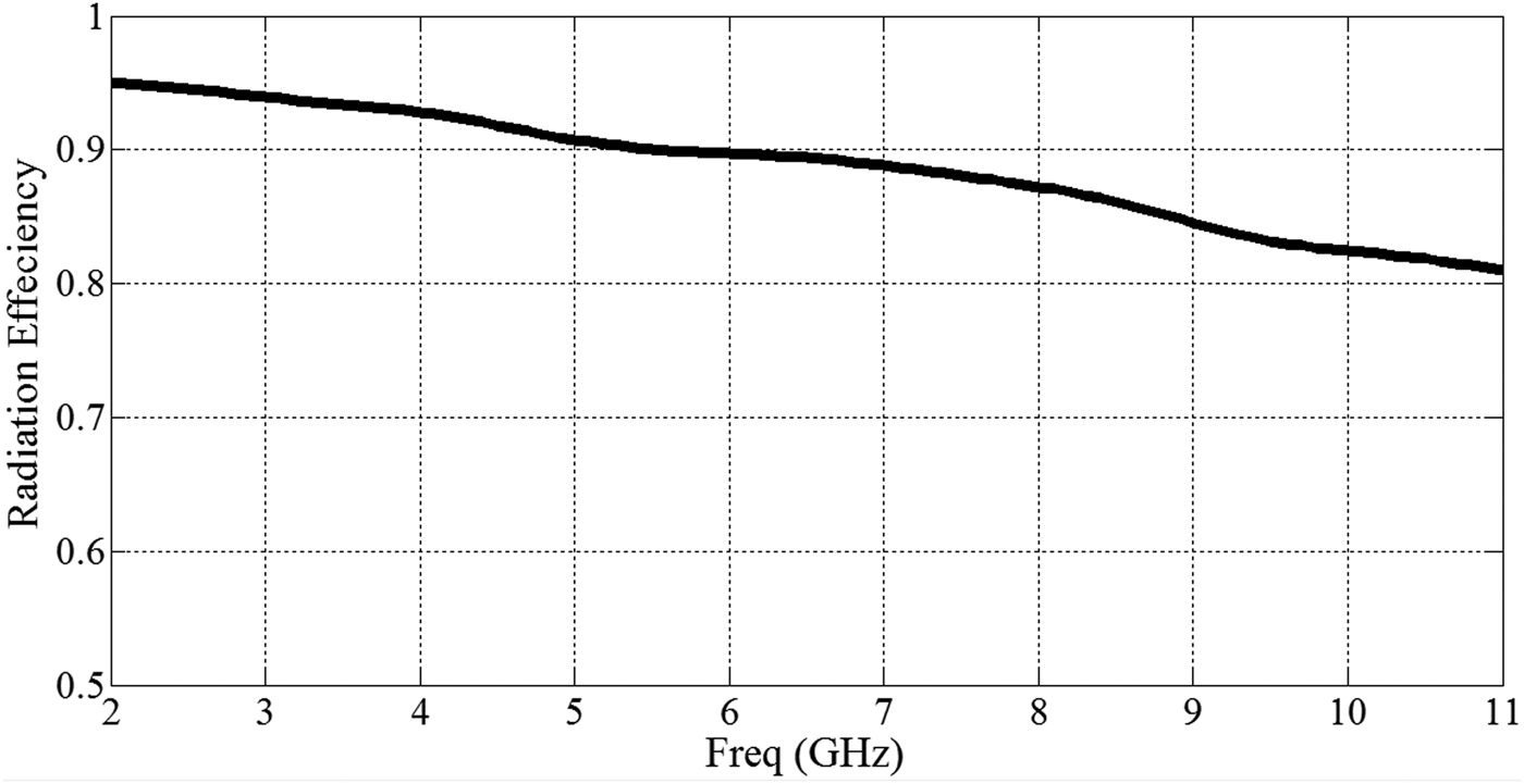
Up to this point, UWB performance of the designed antenna has been proven in terms of return loss, and radiation pattern over the band of interest. In order to complete the investigation of the proposed UWB antenna, radiation efficiency has been studied. Figure 8 demonstrates the simulated radiation efficiency over the frequency band. The radiation efficiency is approximately 95% at 2.2 GHz and decreases through the operating bandwidth slowly to no less than 81% at 10.6 GHz. The average antenna gain extracted over the whole frequency band is almost 3 dB constant. These results tell that the antenna efficiently radiates all over the band of interest.
Simulated radiation efficiency of the proposed UWB antenna.
IV. ANTENNA TIME RESPONSE
In this section, the time response of the proposed UWB antenna is proven to be capable of supporting narrow pulses that cover the defined FCC spectrum for UWB applications. To fulfill this objective, two antennas have been fabricated to function as a transmitting and receiving antennas. The transmission coefficient from one antenna to the other (S 21) separated a distance 120 cm was measured, for different antennas orientations, to represent the system transfer function (magnitude and phase). First-order Rayleigh pulse best fulfills the FCC mask for emission limits [Reference Lamensdorf and Susman18]. The used first-order Rayleigh pulse (a = 45 ps) which covers the UWB FCC bandwidth is expressed as follows:
 $$f\lpar t\rpar \, =\, \; \displaystyle{{ - 2\lpar t - 1\rpar } \over {a^2 }}e^{\left({ - \left({\displaystyle{{t - 1} \over a}} \right)^2 } \right)}\comma \;$$
where, a is the pulse parameter in ps and t is the time in ns.
The chosen pulse was applied to the system transfer function and the system response is calculated, then, passed through the system transfer function (S 21) via convolution process and experienced for being exposed to phase variations of the transfer function all over the band. The output pulse is then depicted at the receiving antenna terminal to see how far it is from the original input pulse. To be able to conduct the convolution process between the Rayleigh pulse and the system transfer function, the latter had to be, first, transformed to the time domain by means of inverse fast Fourier transform (IFFT).
Before explaining the behavior of the system with respect to the input pulse, the system transfer function is going to be studied, first, for both magnitude response and phase response. Thereafter, the pulse will be applied to the system transfer function and the output pulse would be presented and explained in the light of the system transfer function investigation.
The experimental setup for measuring the transmission coefficient (S 21) consists of two identical models of the previously designed UWB antenna, separated by a distance of 120 cm, and connected to the ports of a 2-port vector network analyzer.
Three configurations were conducted, regarding the antennas orientations with respect to each other, Face-to-Face, Face-to-Side, and Side-by-Side, and for each configuration, the transmission coefficient (S 21) is measured.
Firstly, the magnitude response of the system is to be investigated. The measured magnitude of the system transfer function is depicted in Fig. 9 for the three setup configurations. As can be observed from Fig. 9, up to 6 GHz the magnitude of the transfer function for the three antenna orientations is almost the same which is a logic result that can be previously expected from the good omnidirectional characteristics of the pattern at lower frequencies in the specified band. At the upper end of the band, slight differences in the transfer function magnitude are evident. Again, this is a logic result that is evident from the deformations in the omnidirectional pattern, from the perfect omnidirectional shape, at the upper end of the pattern. However, considering the results of the transfer functions (magnitudes at all frequencies and different orientations), and also considering simulated and measured radiation patterns all over the band (radiation characteristics at all orientations and different frequencies), the proposed antenna can be assured to preserve good omnidirectional characteristics all over the band. These results assure good spatial radiation characteristics of transmitted narrow pulse (that covers the band defined by the FCC).
The magnitude response of the transfer function (S 21) for the three conducted setup configurations.
Secondly, the phase response of the system is to be investigated, as its nonlinearity is greatly responsible for the distortion of the pulse in the time domain. The measured phase of the system transfer function all over the band is depicted in Fig. 10. For the sake of visual clarification and ease of detecting nonlinear behavior of the phase response, the values of the phase were unwrapped. As can be seen from Fig. 10, linear phase variation is almost preserved all over the band for the Face-to-Side and Side-by-Side configurations, except for slight nonlinear behavior that makes phase variation is not perfectly linear. On the other hand the Face-to-Face configuration shows deviation from the linear behavior from 7 GHz and up to the end of the band besides the foregoing slight non-normal behavior from 2 to 7 GHz.
The phase response of the transfer function (S 21) for the three conducted setup configurations.
Based on the previous results, one would expect the following: firstly, almost similar response for the system to the input pulse in the cases of Face-to-Side and Side-by-Side configurations. Secondly, different response for the system to the input pulse in the case of Face-to-Face configuration from the other two configurations. Thirdly, on the whole, the received pulse is expected to preserve its shape but would be subjected to ringing due to the previously described nonlinearities in the transfer function phase response. Also, this ringing effect is expected to be more obvious in the case of Face-to-Face configuration. This is due to the deviation from linear behavior that showed up at the upper end of the band. Specifically, from 7 to 11 GHz, deviation from linear behavior was obvious. Although Face-to-Face and Side-by-Side configurations phase responses are almost the same, there exists noticeable difference through the band 7.5–11 GHz. This difference deviates the Face-to-Side configuration phase response a little bit from the linear behavior. To this the imperfect similarity between pulses of the Face-to-Side and Side-by-Side configurations may be referred.
Now it remains to apply the Rayleigh pulse to the measured system transfer function. If the chosen pulse in the time domain is f(t), and the system transfer function in the time domain is h(t), then the received pulse at the terminal of the receiving antenna r(t) is calculated via convolution process as expressed by:
 $$r\lpar t\rpar \, =\, \; f\lpar t\rpar \; \times h\lpar t\rpar .$$
The convolution process was numerically performed using a MATLAB code. The received pulse is then depicted in Fig. 11 which illustrates the normalized measured output pulses through the system for the three measured different setup configurations.
Measured output pulses from the system in different configurations.
It is worth to be mentioned that normalization of the pulses has been done for each signal with respect to its maximum. The purpose of this normalization is to build the comparison between pulses upon the pulse shape in the time domain regardless how much attenuation each pulse suffered from during the path from the terminal of the transmitting antenna to terminal of the receiving antenna.
In the light of the previous analysis to the phase response of the system for the three setup configurations, explain the shape of the measured output pulses can be explained as follows.
First of all, the three pulses corresponding to the three configurations preserve the original shape of the Rayleigh pulse centered at 5 ns with perfect agreement between each other and the original Rayleigh pulse. Mentioning the original Rayleigh pulse, it should be pointed out that an ideal pulse is a one that has the same shape presented in the figure without the ringing effect. Second, due to the slight nonlinear variations in the phase responses of the system for the three configurations, ringing effect is noticed around the pulse as illustrated in Fig. 11. As expected, the Face-to-Side and Side-by-Side configurations pulses are almost of similar level of ringing (the blue and black curves), except for some inversions in the polarity, but the level is almost the same.
On the other hand for the Face-to-Face configuration, sever ringing level (the red curve) is noticed due to the noticeable deviation from the linear performance at the upper end of the band. As mentioned before, these responses were previously expected from the phase responses of the system in different configurations. Eventually, the proposed UWB antenna is assured to be omnidirectionally capable of supporting the shape of a pulse as narrow as 0.25 ns, indicating a good time response of the proposed antenna.
It is worth to be mentioned that the quality of the received pulse can, also, be assessed by the system fidelity factor. Fidelity factor is defined in [Reference Chen, Wu, Li, Yang and Chia19] as:
 $$F\, =\, \; \mathop {max}\limits_t \int_{ - \infty }^\infty {L[ \hat f\lpar t\rpar ] \; \hat r\lpar t - \tau \rpar \, dt}\comma \; $$
where,
 $$\hat f\lpar t\rpar \, =\, \; \displaystyle{{f\lpar t\rpar } \over {\sqrt {\int_{ - \infty }^\infty {\left\vert {f\lpar t\rpar } \right\vert ^2 dt} } }}\comma \; \; \; \hat r\lpar t\rpar \, =\, \; \displaystyle{{r\lpar t\rpar } \over {\sqrt {\mathop \smallint \nolimits_{ - \infty }^\infty \left\vert {r\lpar t\rpar } \right\vert ^2 dt} }}\comma \; $$
are the excitation signal and time-shifted response, respectively, normalized to their energy. It should be mentioned that fidelity factor with the excitation and response signals normalized to their energies preserves amplitude weighting and time shifting. Since the time response of the antenna is function of the direction, it seemed important to measure fidelity factor for different antenna orientations. Same antenna orientations used for measuring system transfer function were used again to give better insight. It was found that, measured fidelity factor for Face-to-Face orientation is 0.898. For Face-to-Side orientation, it is 0.8966. Finally, for Side-by-Side orientation, it is 0.9198. It is evident in [Reference Chen, Wu, Li, Yang and Chia19] that when using Rayleigh pulse as a detection template, maximum fidelity factor is achieved.
V. CONCLUSION
A compact modified CPW semi-circular monopole UWB antenna has been designed, investigated, and validated for typical UWB performance. The antenna introduces compactness features (33.5% size reduction) in comparison with the full version conventional CPW circular antenna. The characterization of the UWB performance of the antenna, over the band 2.2–10.6 GHz, has been validated through investigation of reflection coefficient over the band of interest. The current distributions at selected frequencies spanning the band have been extracted, and from which a stable pattern characteristics were predicted. Radiation pattern at the same frequencies were simulated in 3D, and as predicted, pattern preserved omnidirectional characteristics over the band. For more confirmation on the stability of the pattern over the band, the 2D antenna pattern has been measured, compared to simulated ones, and good agreement is observed. The antenna radiation efficiency over the band of interest showed minimum efficiency of 81% and maximum efficiency of 95%. Finally, time response of the antenna was strictly investigated experimentally to assure the ability of the UWB antenna to support narrow pulses. Narrow Rayleigh pulse, typically 0.25 ns, covering the defined FCC band for UWB applications, was applied to a system of two identical transmitting and receiving antennas separated by 120 cm in three different antennas orientations. The system showed perfect omnidirectional support to the narrow pulse in the different antennas orientations with pulse shape preserving and acceptable ringing level.
Ahmed M. Abdelraheem was born in 1987. He received his B.Sc. degree, with grade of excellent with honor, in Electrical Engineering from the Airborne Communication Department, Military Technical College, Egypt in 2009. He served as an avionics engineer at Cairo airport, where he was responsible for the maintenance of Radar, and communication systems for the C-130 aircraft, in the period 2009–2011. He is, now, with the Military Technical College, since 2011, as a Teaching Assistant at the Department of Electronics Engineering. He is currently working toward M.Sc. degree in Communication and Microwave Engineering at the Military Technical College, Egypt. His research interests include the design and analysis of UWB antennas, electromagnetic band gap (EBG) structures, radiowave propagation modeling, and its application in wireless communications.
 Mahmoud A. Abdalla was born in 1973. He received his B.Sc. degree, with grade of excellent with honors, in Electrical Engineering from the Electronic Engineering Department, Military Technical College, Cairo, Egypt in 1995. He was awarded M.Sc. degree in Electrical Engineering from Military Technical College in 2000, and Ph.D. degree from Microwave and Communication group, School of Electrical Engineering, Manchester University, UK, in 2009. He has been with Military Technical College since 1996 where he is now a lecturer in Electronic Engineering Department. His research has focused on different metamaterial applications in microwave and millimeter bands specially microwave components, miniaturized multiband antennas and ferrite components. Also his research includes electromagnetic energy harvesting systems, EBG components, adaptive antenna systems for DOA estimation and interference cancellations, and radar absorber designs. He has published more than 80 peer-reviewed journal and conference papers. He is currently a reviewer in many electromagnetic journals such as IEEE Antennas and Wireless Propagation Letters, IEEE transaction in Magnetics, IET microwave, antenna and propagation, International Journal of Microwave and Wireless Technologies, Applied Computational Electromagnetic Society, Progress in Electromagnetic Research, European Physical Journal, Applied Physics, Journal of electromagnetic waves (JEMW), and Advanced Electromagnetic. He is also a member of the IEEE and the European Microwave Association EuMA.