I. INTRODUCTION
The reconfigurable antenna has attracted great attention of the researchers and engineers recently due to its potential to improve the property of the wireless communication system [Reference Jiajie, Anguo and Peng1]. For example, the radiation pattern switchable antenna can alter the radiation pattern to the desired direction and improve both the system gain and security [Reference Mahmood and Denidni2]. The polarization reconfigurable antenna is capable to provide dual channels for frequency-reuse transceivers and transporters [Reference Li, Zhang and Chen3], and to mitigate the detrimental fading in the rich scattering environment. The frequency reconfigurable antenna can be used in the different system and it can be used as more than one antenna in complex system, especially they are suitable to be applied in the compact devices [Reference Nguyen-Trong, Hall and Fumeaux4, Reference Sharma and Tripathi5]. Polarization is an important feature of the antenna, and a large number of polarization reconfigurable antennas have been reported [Reference Nishamol, Sarin and Tony6–Reference Kim, Pan and Nikolaou9], but most of these designs are reconfigured between the dual orthogonal linear polarization (LP) modes or between the right-handed circular polarization (RHCP) and left-handed circular polarization (LHCP) [Reference Singh, Kanaujia, Dwari, Pandey and Kumar10, Reference Sulakshana and Anjaneyulu11], and nearly all of them operate in a single operating band. Few designs are the reconfigurable antennas with tri-polarization or quadri-polarization mode based on the PIN diode switch [Reference Wu, Wu and Lai12–Reference Gao, Zhong and Zhang16]. For the convenience of comparison, the characteristics of the multi-polarization diversity antenna, including the resonance frequency, the number of ports, the dimension, and polarization diversity are listed in Table 1, and the same for all of the reference antennas is that they are operating in a narrow-frequency band.
Characteristics comparison of the reported antennas in reference.

Multiband is another attractive feature for the uniplanar antenna [Reference Chen and Yung17–Reference Chen and Yung21], which is capable to simplify the entire system and improve the performance of the wireless communication. Most of the uniplanar antennas with multiple operating bands have the identical polarization mode in all bands, or some have the different polarization mode in the different bands [Reference Zhou, Wang and Wang19]. The antenna in [Reference Qin, Guo and Ding22] has the capability of switching polarization in dual bands simultaneously, while the reconfigurable polarization mode is only the LP mode with the different directions in the same plane.
The uniplanar antenna has a lot of advantages, such as feasible integration with the active devices and the MMICs, via-free and the facility to be fabricated [Reference Wang and Chen23–Reference Chacko, Augustin and Denidni25], compared with the microstrip and other traditional antennas. Furthermore, the uniplanar antenna is an intrinsic broadband antenna; therefore it is widely used in the wideband antenna design [Reference Sze, Hsu and Chen26–Reference Xue, Yang and Ma29].
In this communication, a reconfigurable uniplanar antenna with triple switchable polarization modes, including the LP, RHCP, and LHCP is proposed, most of all, the polarization of the proposed antenna is capable to be tuned simultaneously in dual-frequency bands. The proposed antenna is comprised a coplanar waveguide (CPW)-fed line, a closed slot surrounded by the strip extended from the ground of the CPW transmission feed line, a T-shaped strip and three groups of the patches as well as PIN diodes. The reconfiguration of the presented antenna is realized by connecting the different patches to both the central T-shaped strip and the fringe line. The commercial full wave simulation software HFSS is employed in the antenna design and optimization, meanwhile the proposed antenna is fabricated for the experimental test. The investigated characteristics of the proposed reconfigurable antenna include the scattering coefficient, axial ratio (AR), radiation pattern, gain and radiation efficiency, the simulated results are agreed well with the measured results. The dual central frequencies of the overlapped bands are 2.63 GHz (17.8%) and 4.42 GHz (3.40%), respectively, and first resonance frequency band covers the WLAN specification (2.40–2.48 GHz), the second band can be applied in the 5 G mobile communication (4.40–4.50 GHz). It is necessary to note that the uniplanar antenna has dual radiation pattern peaks with the direction of +z and −z-axes, and the determination of the LHCP or RHCP mode is related to the direction of the microwave propagation. Polarization mode especially the RHCP/LHCP is discussed in this communication in term of the reference microwave propagation direction of the +z axis.
II. RECONFIGURABLE ANTENNA DESIGN
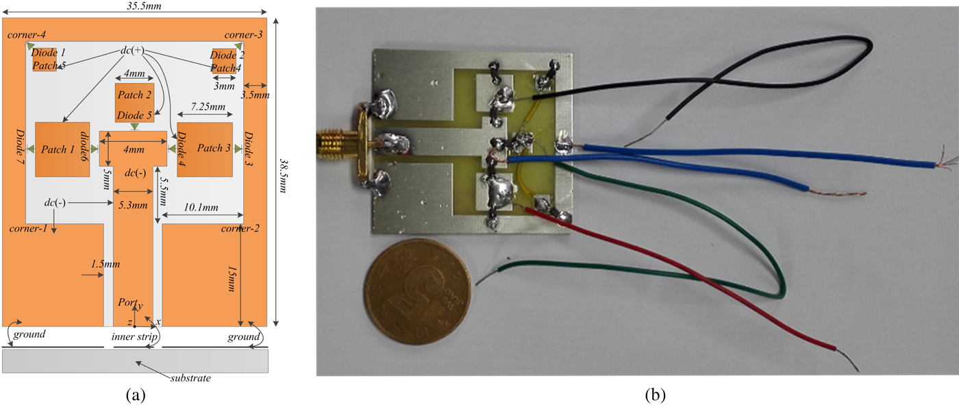
The configuration and geometrical parameters of the proposed tri-polarization reconfigurable antenna with seven PIN diodes is shown in Fig. 1. The antenna is fed by a 50 Ω CPW transmission line with the width of 5.3 mm for the inner strip and gaps of g = 1.5 mm from the inner strip to the ground plane, therefore all the metal design is fabricated in the same surface of the substrate. The substrate has the thickness of 1.6 mm, the dimension of 35.5 mm × 38.5 mm, and it is composed of the common commercial dielectric medium FR4 with the dielectric constant of 4.4, the loss tangent of 0.02. The whole antenna metal configuration is composed of the CPW-fed transmission line with a rectangle slot closed by the strip extended from the ground plane, a central T-shaped printed driven stub and another five square metal patches arranged in the different place of the rectangular slot shown in Fig. 1. For the convenience of description, the five separate metal patches are named patches 1, 2, 3, 4, and 5, respectively. The five patches are connected to the central T-shaped strip or the fringe-extended ground of the CPW through the PIN diodes, therefore the distance from the patches to the T-shaped strip or the fringe ground is fixed at 1 mm for consideration of the PIN diodes installation. The seven PIN diodes (named diodes #1, #2, #3, #4, #5, #6, and #7) are employed as the electrical switches for the radio frequency (RF) surface current, and seven bias lines for supplying the diodes positive or negative direct current (DC) voltage are needed to be soldered to the patches and the ground of the CPW in the fabricated antenna.
(a) Geometry of the proposed reconfigurable antenna with the PIN diodes and the optimized geometrical parameters. (b) Proposed antenna prototype.

Patches 1, 2 and 3 are used to reconfigure the driven stub of the proposed closed slot antenna, and the patches 4 and 5 are etched for regulating the resonance frequency in the LP mode. It is clear that the structure of the antenna in the RHCP mode is a symmetrical mirror image to that in the LHCP mode; nevertheless, the structure of the antenna in the LP mode is symmetrical and in order to resonate in the same frequency to the circular polarization (CP) mode, patches 4 and 5 are added.
III. RECONFIGURATION AND PRINCIPLE ANALYSIS
A) Polarization reconfigurable mechanism
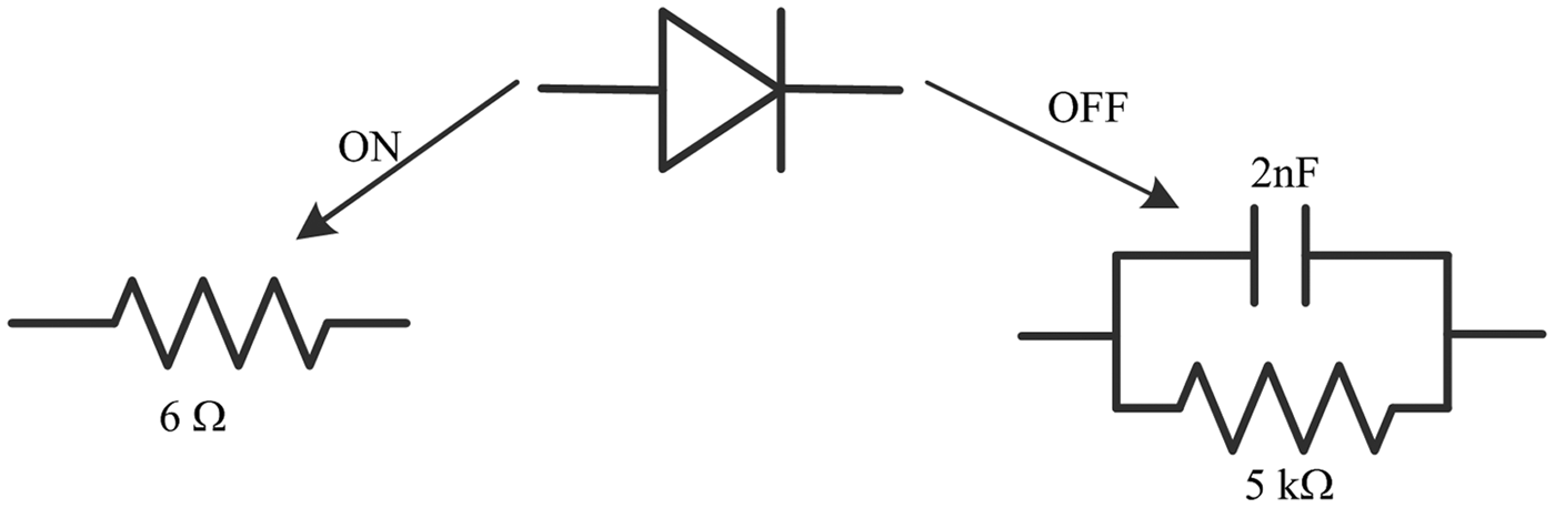
The radiation characteristic of the proposed CPW-fed closed slot antenna is greatly related to the driven stub. The triple polarization modes of the proposed reconfigurable antenna is switched by connecting the different patches to the T-shaped strip and the fringe extended ground of the CPW transmission line, and the PIN diodes here are used as the electrical switches. The PIN diode (1N4148) is biased with forward voltage of 1 V and forward current of 150 mA, the equivalent circuit model when biased the forward and the reverse voltage is shown in Fig. 2. The forward series resistance is too small to affect the radiation feature of the antenna, and the PIN diodes act as the electrical short circuit. In off-state, the shunt resistance with value of 5 kΩ is equivalent to the ideal open circuit and the shunt capacitance yields to the intrinsic capacitance between the separated patches and the T-shaped strip or the extended ground of the CPW transmission line. Finally the PIN diodes are capable to work as the ideal switch for the RF signal.
Equivalent circuit model of the PIN diode in on/off states.

The five patches and seven PIN diodes can be divided into three groups to generate three polarization modes (LP, RHCP, and LHCP). Patch 2, patch 4, patch 5, diode #1, diode #2, and diode #5 are a group to produce the LP mode; patch 1, diode #6, and diode #7 to generate the RHCP mode; and the patch 3, diode #3, and diode #4 to generate the RHCP mode. When the patches 2, 3, and 5 are offered with a positive DC voltage and the T-shaped strip, the ground of the CPW transmission line are offered with a negative DC voltage, the diodes #1, #2, and #5 are in on-state and the other diodes is in off-state. In this case, the entire structure of the antenna is symmetric and the proposed reconfigurable antenna operates in the LP mode. When the patch 1 is supplied with a positive DC voltage and the T-shaped strip, the ground of the CPW transmission line are supplied with a negative DC voltage, the diodes #3 and #4 are in on-state and the other diodes are in “off-state”. The proposed antenna is capable to radiate the LHCP microwave and the last case is that the diodes #6 and #7 are in on-state, the antenna operates in the RHCP mode. The polarization modes of the reconfigurable antenna are listed in Table 2.
Triple polarization modes of the proposed reconfigurable antenna.

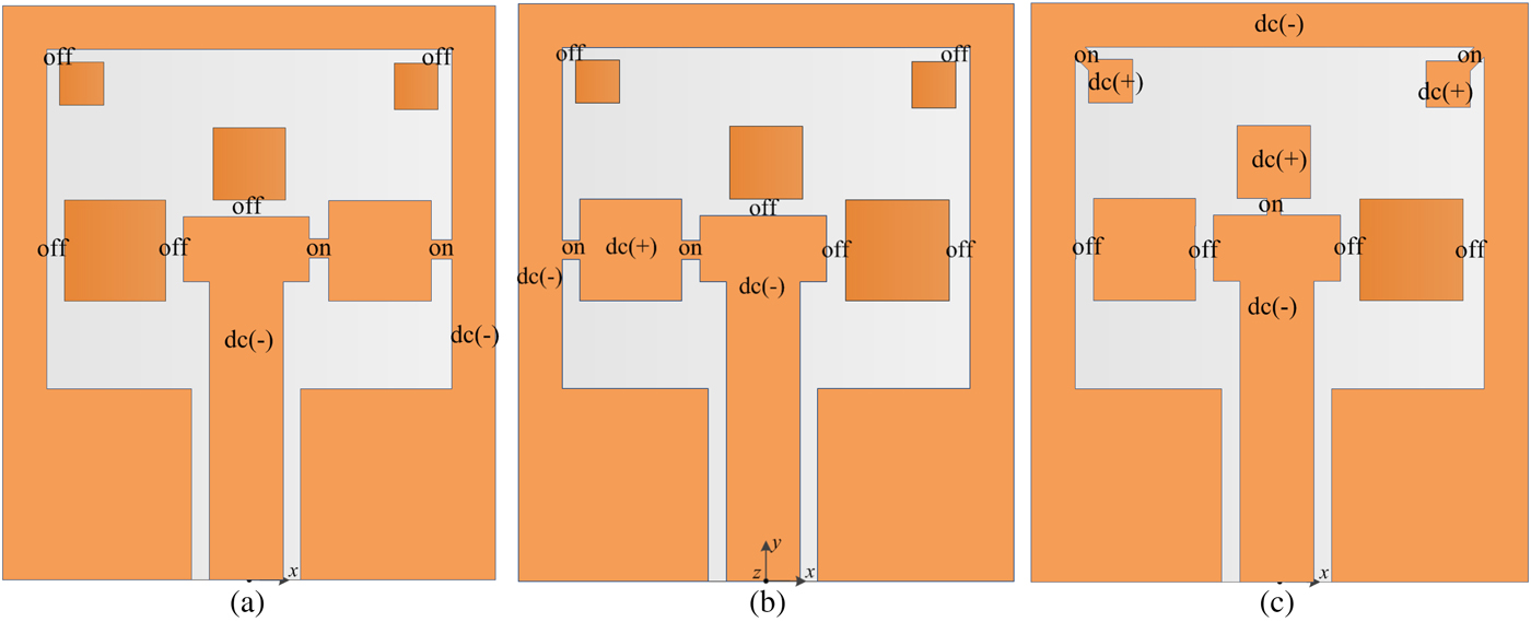
Based on the above analysis of the PIN diode, the diodes in on-state can be equivalent to be a shorted circuit whereas the diodes in off-state can be considered as an open circuit in the simulated analysis. The antenna in three polarization mode is illustrated in Fig. 3, and the diodes biased forward voltage are replaced by metal patches and the diodes are removed when they are biased with the reversed voltage.
Equivalent structure of the reconfigurable antenna for three polarization modes (a) the diodes 6# and 7# is in on-state (b) the diodes 3# and 4# is in on-state (c) the diodes 1#, 2#, and 5# is on-state.

B) Operation principle
A large number of the CPW-fed slot antennas have been reported in the last decade [Reference Chen, Chen and Hsu30–Reference Cao and Yu34], and most of them are analyzed by means of the equivalent surface magnetic current distributions in the slot area [Reference Chen, Chen and Hsu30, Reference Wang and Lin31, Reference Li, Zhai and Li33], whereas some others are analyzed by the surface electrical current distribution in the metal strips of the design [Reference Xue, Yang and Ma29, Reference Li, Zhai and Li33–Reference Malek, Hakimi and Rahim35]. After a detail analysis of the most geometrical parameters in the design, the principle of the dual resonance frequencies of the proposed antenna can be summarized as following.
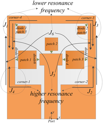
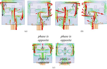
For the proposed antenna, the CP modes are generated from four orthogonal corners around the slot shown in Fig. 4. The RHCP wave is radiated from the J 1 and J 2, and the LHCP wave is from the J 3 and J 4. For the RHCP radiation mode, the current path of J 1 is longer than the J 2; therefore the resonance frequency of J 1 is lower than that of J 2. Consequently, the resonance frequency f r1 = 2.63 GHz is from the J 1 and the f r2 = 4.42 GHz is from the J 2. The LHCP radiation mode is from the J 3 and J 4, the similar to the RHCP radiation mode. The LP mode is a little different from the CP mode. The dual resonance frequencies in the LP mode are from the J 5 and J 6, respectively. The currents along the edges parallel to the x-axis are not capable to radiate the wave, since the phase of current distributed in the right and left is opposite, which are illustrated in Fig. 5. In order to further illustrate the resonance principle, the numerical simulation for the RHCP, LHCP, and LP modes is carried out, and it is necessary to note that the PIN diodes are replaced by a metal strip in the simulation by HFSS software when it is in on-state. The surface current distribution for the RHCP, LHCP, and LP modes is shown in Fig. 5.
Resonance modes of the proposed reconfigurable antenna.

Simulated surface current distributions of the proposed antenna for: (a) RHCP, (b) LHCP, and (c) LP at f r1 = 2.63 GHz, f r2 = 4.42 GHz.

IV. SIMULATED AND EXPERIMENT RESULTS
The proposed polarization reconfigurable antenna has been investigated by both the numerical simulation and experimental measurements. The results, including the scattering coefficient, AR, radiation pattern, gain, and radiation efficiency are analyzed in this section. The simulated results are carried out by the commercial software HFSS and the experimental results are conducted by the Agilent Technologies PNA Series Network Analyzer E8363B and in the anechoic chamber. Some of the results including both the simulated and the measured are similar with each other, which can be accounted for the symmetrical mirror image structure in the RHCP and LHCP states. There are seven PIN diodes applied as the electrical switches, which have an influence on the performance of the proposed reconfigurable antenna, such as the forward series resistance shown in Fig. 2 perhaps impacts the radiation efficiency, the little conduction current through the reverse large shunt resistance enhances the cross polarization mode, and the shunt capacitance affects the port matching. Furthermore, seven DC lines welded to the metal patches are employed to provide the DC-biased voltage for the PIN diodes. All of them will impact the measured results more or less and the measured results are also related to the measurement environment especially the anechoic chamber.
A) Scattering coefficient
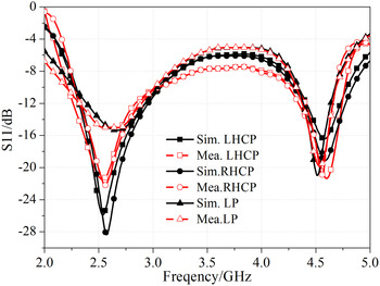
The simulated and measured scattering coefficient of the proposed polarization reconfigurable antenna in three polarization modes is plotted in Fig. 6, which is also listed in Table 2. As can be seen that the simulated and measured results are agreed well with each other, and the tiny discrepancy attributes to poor welding points in the fabricated prototype, the PIN diodes and the DC-biased lines with different length. Table 3 shows that the polarization mode can be tuned in the lower band from 2.30 to 3.04 GHz (27.7%) and the higher frequency band from 4.34 to 4.67 GHz (7.32%).
Simulated and measured scattering coefficients of the proposed reconfigurable antenna in three polarization modes.

Impedance bandwidth of the proposed antenna in different polarization modes.

B) Axial ratio
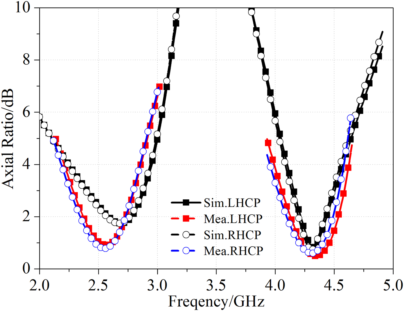
The simulated and measured AR of the proposed reconfigurable antenna in the RHCP and LHCP modes are illustrated in Fig. 7 and listed in Table 4. It can be observed that the simulated AR in the RHCP and LHCP modes are similar for their mirror image structures, mentioned above.
Measured and simulated AR of the reconfigurable antenna in the CP mode.

Axial ratio of the proposed antenna in the RHCP/LHCP modes.

The polarization reconfigurable antenna should be operating in the same frequency band. It can be seen that the measured 3 dB AR bandwidths are a little wider than the simulated ones in Fig. 7, the dual overlapped RHCP and LHCP simulated 3 dB AR bandwidths are from 2.40 to 2.87 GHz (17.8%) and from 4.16 to 4.49 GHz (7.6%), meanwhile, the dual overlapped measured 3 dB AR bandwidths are from 2.29 to 2.79 GHz (15.4%) and from 4.06 to 4.54 GHz (11.2%). Compared with the impedance bandwidth, the lower 3 dB AR bandwidth is completely covered by the impedance band shown in Fig. 6, but the higher 3 dB AR bandwidth is partially included by the impedance band. Finally, the proposed antenna is capable to radiate the RHCP, LHCP, and LP wave in the dual bands with central frequencies of both 2.60 GHz (2.40–2.87 GHz, 17.8%) and 4.42 GHz (4.34–4.49 GHz, 3.40%).
C) Radiation pattern
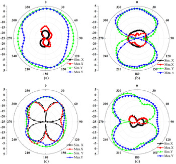
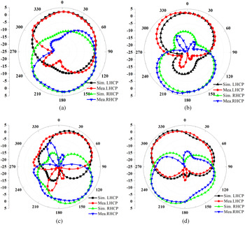
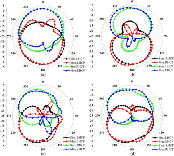
The simulated and measured radiation patterns of the presented reconfigurable antenna in the two orthogonal principle planes (xoz- and yoz-planes) at 2.63 and 4.42 GHz for triple polarization modes are shown in Figs 8–10, respectively. The maximum radiation direction has been normalized to the same value for convenience to comparison. This design is a uniplanar antenna; therefore the antenna is capable to radiate the wave along both the +z and −z axes.
Simulated and measured radiation pattern of the proposed reconfigurable antenna in the LP mode (a, b) at 2.63 GHz and (c, d) at 4.42 GHz.

Simulated and measured radiation patterns of the proposed reconfigurable antenna in the LHCP mode (a, b) at 2.63 GHz and (c, d) at 4.42 GHz.

Simulated and measured radiation patterns of the proposed reconfigurable antenna in the RHCP mode (a, b) at 2.63 GHz and (c, d) at 4.42 GHz.

The measured radiation pattern is affected by the fabrication error, poor welding technique, seven DC lines providing the forward and reverse biased voltages for the PIN diodes and measurement environment, therefore the measured radiation patterns are less smooth than the simulated ones and the backward radiation is tested in some cases, but the simulated and measured radiation pattern is well agreed with each other at large. The symmetrical structure of the proposed antenna in the LP mode results in the symmetrical radiation pattern in the xoz-plane. At 2.63 GHz the antenna has a good omni-directional cross-polarization discrimination (XPD), the XPD at 4.42 GHz in the maximum radiation direction (+z or −z-axes) is still preferable shown in Fig. 8. For the RHCP/LHCP modes, the structure of the proposed antenna is asymmetrical, since the series inductance and resistance is equivalent to the pin diodes in on-state and the shunt capacitance is for the pin diodes in off-state; hence, the radiation patterns are also asymmetrical. But the structure of the proposed antenna in the RHCP and the LHCP modes is symmetrical mirror image to each other, as can be observed that the radiation patterns are also the mirror image shown in Figs 9 and 10, a little deviation is from the fabrication error or the measurement processes discussed above.
D) Radiation efficiency and gain
The measured radiation efficiency and gain are plotted in Fig. 11. Different from the microstrip antenna, the uniplanar antenna can radiate the microwave along both the +z and −z-axis, and more energy can be radiated. Although there is some loss in the FR4 substrate and conductor in the surface of the substrate, the radiation efficiency of the proposed antenna is >93% in the first band and 92% in the second band shown for the tri-polarization modes in Fig. 11(a). The gain is bigger than 2.30 and 3.52 dB in the first and second band respectively shown in Fig. 11(b). It can be observed that the gain in the second higher frequency band is bigger than that in the first band. The gain is not only related to the port matching, but also to the half power beam width (HPBW). The radiation patterns in Fig. 8–10 reveal the bigger HPBW of frequency 4.42 GHz relative to 2.63 GHz.
(a) Measured radiation efficiency and (b) gain of the proposed tri-polarization reconfigurable antenna.

V. CONCLUSION
A tri-polarization reconfigurable antenna simultaneously in the dual-frequency bands is proposed in this communication. Furthermore, the investigated antenna has a simple structure and all the metal designs are printed in the same surface of the substrate, which is adopted to be widely used. The radiation characteristics of the antenna have been investigated in detail and the performance is well enough to be applied. The simulated and the measured results shows that the antenna can be applied in both the WLAN 2.4 GHz wireless communication and 5 G communication, which will be put into practice in near future.
 Haixiong Li was born in Shannxi Province, China, in 1982. IEEE Student Member, CIE Student Member. He received the B.Sc. degree from the School of Electrical Information Science & Engineering, Lanzhou University in Lanzhou city, China, in 2006. He received the M.Sc. degree from the School of Information Science and Technology, Xiamen University in Xiamen city, China in 2013. He is presently working on his doctoral degree in School of Electronics and Information, Northwestern Polytechnical University in Xi'an city, China. His research interests include electromagnetic metamaterials and MIMO antenna design.
 Yunlong Gong was born in Shanxi Province, China, in 1991. He received the B.S. degree in Electrical Engineering from the Xidian University in Xi'an city, China, in 2014. He works for M.S. degree in Northwestern Polytechnical University. His research interests includes: reconfigurable antenna and matesurface.
 Jiakai Zhang was born in Shannxi Province, China, in 1990. He received the master degree from the School of Electronics and Information, Northwestern Polytechnical University in Xi'an city, China, in 2015. He works for doctor degree in Northwestern Polytechnical University. His research interests include matematerials, RCS reduction of the antenna.
 Jun Ding was born in Shannxi Province, China, in 1964. She received the M.Sc., B.Sc., and Ph.D. in the School of Electronics and Information, Northwestern Polytechnical University in Xi'an city, China, in 1986, 1989, and 2005, respectively. She is a professor in School of Electronics and Information NWPU. She has published more than 100 research papers. Her research interests include electromagnetic metamaterials, the antenna theory and design, and the microwave circuit design.
 Chenjiang Guo was born in Shannxi Province, China, in 1963. CIE Senior Member, Antenna Society Committee Member. He received the M.Sc., B.Sc., and Ph.D. from the School of Electronics and Information, Northwestern Polytechnical University in Xi'an city, China, in 1984, 1987, and 2007, respectively. He is a Professor in the School of Electronics and Information NWPU. He has published more than 140 research papers. He research interests includes EMI/EMC, the antenna theory and design, and the microwave circuit design.