Fundamental properties of ferrofluids
Ferrofluids are suspensions of magnetic nanoparticles in appropriate carrier liquids. The magnetic particles are usually magnetite (Fe3O4) or cobalt with a mean diameter on the order of 10 nm. The particles are coated with surfactant molecules to prevent agglomeration due to van der Waals interactions for times up to decades. A liquid dispersion of magnetic nanoparticles is considered to be a ferrofluid if it behaves as a uniform magnetic liquid and the particles are not separated from the solvent by an external magnetic field. Since the first preparation of a ferrofluid by Steve Papell, Reference Papell1 numerous methods to prepare ferrofluids have been reported, including the co-precipitation methods of Khalafalla and Reimers. Reference Khalafalla and Reimers2 The most common particle used in ferrofluids is magnetite, since oxidation does not cause a degradation of magnetic properties, unlike the reduction in magnetization when Fe or Co oxidizes. Recently, Bönnemann et al. Reference Bönnemann, Brijoux, Brinkmann, Matoussevitch, Waldofner, Palina and Modrow3 have shown a way to produce iron as well as cobalt nanoparticles with an aluminium oxide shell to overcome this.
The most important property of ferrofluids is high initial susceptibility (i.e., χ = M/H, at low fields, where M is the magnetization and H is the magnetic field) about four orders of magnitude larger than in common molecular paramagnets. This allows for the possibility to produce strong magnetic forces with weak fields, making numerous applications possible. Reference Rosensweig4–Reference Odenbach6 In the following, we discuss possibilities to control the flow of ferrofluids by magnetic fields, changes in their basic fluid properties in the presence of magnetic fields, as well as applications of ferrofluids.
Flow control by magnetic forces
Readers interested in a deep theoretical approach to fluid mechanics of ferrofluids are referred to the book by Rosensweig Reference Rosensweig4 as well as to recent developments in ferrofluid dynamics summarized in a review article by Müller et al. Reference Müller and Liu7 To calculate magnetic field effects, the Bernoulli equation has to be extended by a magnetic term, including the energy of the ferrofluid in a magnetic field: Reference Rosensweig4
 $${\rho \over 2}{v^2} + \rho gh - {\mu _0}MH = const.$$
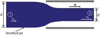
Here, v denotes the velocity of the fluid, ρ is its density, h is the height used to calculate potential energy, μ0 is the permeability of free space, and g is the gravitational acceleration. Consider a free jet of a ferrofluid, as shown in Figure 1 —with a diameter a 1 and a velocity v 1—which enters a homogenous magnetic field aligned parallel to the flow direction of the jet. The magnetic energy term in Equation 1 changes from zero at point 1 to a finite negative value at point 2.
The magnetic nozzle. The ferrofluid enters from point 1 and travels to point 2. A homogeneous magnetic field is aligned parallel to the flow direction. Note: a 1, diameter of nozzle at point 1; a 2, diameter of nozzle at point 2; H, magnetic field; v 1, velocity of the fluid at point 1; v 2, velocity of fluid at point 2.

Assuming that pressure as well as potential energy do not change between points (1) and (2), it becomes obvious that the change in magnetic energy has to be compensated by a change in kinetic energy of the jet. Due to the negative sign of the magnetic energy, the velocity of the jet has to increase after entering the magnetic field region. Since the ferrofluid is an incompressible liquid, the continuity equation for mass transport requires a reduction of the jet diameter.
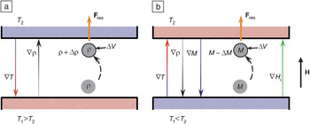
Consider a horizontal layer of a liquid, as shown in Figure 2 a, heated from below and cooled at the upper boundary. The temperature gradient generates a density gradient inside the liquid layer that is antiparallel to the temperature gradient. Assuming that a volume element of the liquid is moved adiabatically from the hot lower region of the fluid toward the colder wall, this volume element will have a lower density than the surrounding liquid. Thus, the volume element will experience buoyancy in the gravitational field, which will act in the direction of the original displacement. Buoyant forces are able to destabilize the fluid layer, and they can cause a convective flow, which is opposed by thermal conductivity and viscous friction in the liquid.
Schematic of the driving force of thermal and thermomagnetic convection. (a) The liquid layer is heated from below and cooled from above. (b) The liquid layer is cooled from below and heated from above. Note: T 1, temperature of lower boundary; T 2, temperature of upper boundary; ∇T, gradient of the temperature; ρ, density; Δρ, change in density; ∇ρ, gradient of the density; ΔV, change in volume; F res, additional driving force; M, magnetization; ΔM, change in magnetization; ∇M, gradient of the magnetization; H, magnetic field; ∇H, gradient of the magnetic field inside the ferrofluid.

If one considers the opposite situation, in which the lower boundary of the fluid layer is cooled and the upper one is heated, one obtains a stable density stratification, and no convective flow can appear. This problem of thermal convection is one of the classical standard problems of fluid mechanics. Reference Bénard8 Assume now a ferrofluid layer is subjected to a magnetic field parallel to the temperature gradient. As shown in Figure 2b, an additional driving force is generated by the interaction of the magnetic field with the ferrofluid, which itself can lead to a convective flow.
Assuming that a volume element in the fluid layer shown in Figure 2b is transferred from the cold lower wall toward the hot upper boundary, and taking into account that the magnetization will decrease with increasing temperature, the displaced volume element will have a higher magnetization compared to its surroundings. Since the temperature gradient gives rise to a gradient in magnetization, which is antiparallel to the temperature gradient as mentioned previously, the magnetic field H i inside the ferrofluid given by H i = H–DM, where D denotes the demagnetization factor of the fluid layer, shows a gradient antiparallel to the magnetization gradient. Therefore, the volume element of the fluid will experience a magnetic force in the direction of the magnetic field gradient. Thermomagnetic convection couples with normal thermal convection, resulting in complex flow behavior and complex flow structures Reference Schwab, Hildebrandt and Stierstadt9 as under conditions of reduced gravity. Reference Odenbach10
A major challenge in experimental investigations of flow phenomena in ferrofluids is the detection of changes in the flow structure. Ferrofluids themselves are opaque, and thus the standard measuring techniques from fluid mechanics cannot be used. For thermomagnetic convection, most of the alternative methods are based on the fact that the convective flow will change the temperature profile at the fluid layer boundaries. Reference Schwab, Hildebrandt and Stierstadt9–Reference Polevikov and Fertman11 Other experiments Reference Engler and Odenbach12 have analyzed the heat flux through a ferrofluid layer, which changes significantly with convection. This technique also provides a very robust signal, which can be used to determine the onset of thermomagnetic convection. Among the changes in ferrofluid properties that can be induced by a magnetic field, the increase of the viscosity by magnetic fields is the most prominent example and causes the strongest changes in the flow behavior.
Field-dependent fluid properties
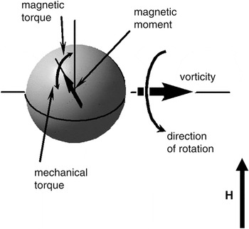
Most of the properties of a ferrofluid can be influenced by external magnetic fields, for example, the thermal conductivity Reference Krichler and Odenbach13 as well as the Soret effect, Reference Völker and Odenbach14 which depend on field strength and the relative alignment of the magnetic field with the temperature gradient. However, fluid viscosity experiences the most significant change in a magnetic field. This was first discovered by McTague. Reference McTague15 This change in the viscous properties of a ferrofluid can easily be understood if one considers a magnetic particle under shear flow, as shown in Figure 3 .
A ferrofluid in a shear flow with magnetic field aligned perpendicular to the vorticity of the flow for explaining rotational viscosity. H, magnetic field.

If the magnetic moment of a particle is fixed within the particle, it will rotate with the magnetic particle under shear flow. This is valid for magnetite particles with a size of about 13 nm, since for such particles, the Brownian relaxation time Reference Brown17 will become smaller than the Néel relaxation time. Reference Néel18 If the magnetic field is applied perpendicular to the vorticity of the flow, the rotation of the magnetic moment will lead to a misalignment of the magnetic moment and the magnetic field. This misalignment itself will give rise to a magnetic torque counteracting the mechanical torque acting on the particle, and thus hindering the free rotation of the particles in the flow and increasing the fluid viscosity. Alignment of the magnetic field parallel to the viscosity of the flow will not cause any change in the free rotation of the particles and will thus not cause an increase of viscosity. Reference Shliomis16 This also neglects dipolar interactions between particles.
Experimentally, a change in viscosity orders of magnitude larger is observed, and this is ascribed to chain formation of magnetic nanoparticles within the liquid. Reference Jordan19 This approach was first used to explain the field and shear rate dependent changes in viscosity in a ferrofluid subjected to magnetic fields. Reference Odenbach and Stoerk20 However, it has been proven experimentally Reference Odenbach and Raj21,Reference Ilg, Odenbach and Odenbach23 and modeled theoretically Reference Zubarev, Odenbach and Fleischer22 that the magneto-viscous effect depends on the amount of large particles inside the ferrofluid. The chain formation causes not only an increase in the viscosity of a ferrofluid, but also non-Newtonian effects such as normal stress differences, Reference Odenbach, Rylewicz and Rath24 viscoelastic properties, Reference Thurm and Odenbach25 as well as the appearance of a yield stress in ferrofluids. Reference Shahnazian and Odenbach26 Most of these effects are too small to be useful for technical applications, unlike the yield stress for magneto-rheological fluids that contain micron-sized magnetic particles that result in fluids with much more pronounced rheological changes to applied fields. Reference Bossis, Volkova, Lacis, Meunier and Odenbach27
Applications of ferrofluids
An overview of possibilities for applications of ferrofluids is given in Reference Reference Berkovsky and Bashtovoy28. Many of these applications rely on a magnetic field gradient to position the magnetic fluid at a certain point inside a device. Here, we discuss two important examples of technical applications of magnetic fluids, for cooling loudspeakers and for frictionless sealing of rotary feedthroughs.
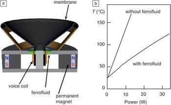
Figure 4 shows the use of a magnetic fluid in a loudspeaker. The fluid is positioned by magnetic field gradients produced by permanent magnets contained in the loudspeaker in such a way that the voice coil is suspended in a ferrofluid ring. A thermal bridge between the voice coil heated by Ohmic losses and the main structure of the loudspeaker is established, where the loudspeaker can be cooled from outside. In high power loudspeakers as well as in miniaturized systems, these ferrofluid bridges enhance the power of a loudspeaker by a factor of three. Reference Raj and Moskowitz29
(a) Schematic of the cooling of a loudspeaker with a ferrofluid, and (b) the power dependence of the speaker’s temperature (T) with and without the ferrofluid.

A similar method of positioning the ferrofluid by means of magnetic field gradient is shown in Figure 5 , which depicts the use of ferrofluids as a frictionless seal in a rotary feedthrough. The fluid is positioned by the magnetic field gradient produced by permanent magnets embedded in the feedthrough within the gap between the rotating shaft and the housing. With permanent magnets and highly concentrated ferrofluids, forces can be produced that are large enough to seal the feedthrough up to pressure differences of ∼1 bar (100 kPa).
Schematic sketch of a ferrofluid seal in a rotary feedthrough. The ferrofluid stays in position between the rotating shaft and the housing unit due to the magnetic field gradient produced by the permanent magnets. The combination of the ferrofluid and the permanent magnets creates large enough forces to seal the feedthrough.

Conclusions and outlook
In a well-stabilized superparamagnetic suspension, the high initial susceptibility of ferrofluids provides an opportunity to generate magnetic forces that can compete with gravity. These forces can be used to control flow of ferrofluids through magnetically induced changes in the rheological behavior. Despite the fact that ferrofluids have been studied for about 50 years, there are still numerous open questions. The most important future direction of research is in smart materials containing magnetic particles that will need to consider the interaction between the magnetic particles and complex matrices. The simple inclusion of magnetic particles in an elastomeric matrix Reference Filipcsei, Csetneki, Szilágyi and Zrínyi30 has already led to a new class of smart materials called magneto-rheological elastomers. An increasing understanding of the structures of these elastomers Reference Borbath, Günther, Borin, Gundermann and Odenbach31 and their role in magnetic field response, Reference Günther, Borin, Günther and Odenbach32 together with new techniques to control the binding of the particles to the elastomeric matrix, Reference Kaleta and Lewandowski33 are anticipated to lead to a new class of smart materials with a high potential for technical applications.