Introduction
Ti and its alloys have been increasingly applied to implant materials due to their light weight, good mechanical properties, excellent corrosion resistance, and biocompatibility [Reference Kunčická, Kocich and Lowe1]. The most common Ti-based alloys used in orthopedics are of α- and (α + β)-type nature and show relatively high Young’s modulus (110–120 GPa) in comparison with that of bone (<30 GPa) [Reference Wang, Li, Hu and Kou2, Reference Ozan, Lin, Li, Ipek and Wen3]. The Young’s modulus mismatch leads to the stress shielding for patients after surgeries, thus resulting in bone resorption and final implant loosening [Reference Black4]. Recent researches show that β Ti alloys have a lower elastic modulus, improved biological properties, and cold forming capacity [Reference Liang, Feng, Yin, Liu, Ma and Liu5, Reference Boyer, Welsch and Collings6]. To this end, the development of β Ti alloys with the addition of β-stabilizers in suitable amount, including Ti–Zr, Ti–Ta, Ti–Mo, Ti–Nb, Ti–Nb–Zr, Ti–Nb–Ta, Ti–Ta–Zr, Ti–Fe–Ta, Ti–Zr–Mo, Ti–Nb–Zr–Sn, Ti–Al–Cr–Nb, Ti–Nb–Ta–Zr, Ti–Mo–Zr–Nb, Ti–Zr–Fe–Mn, and other alloys, has been made recently [Reference Wang, Li, Hu and Kou2, Reference Ozan, Lin, Li, Ipek and Wen3, Reference Black4, Reference Liang, Feng, Yin, Liu, Ma and Liu5, Reference Boyer, Welsch and Collings6, Reference Kumar and Sankara Narayanan7, Reference Li, L Ye, Yuan and Yu8, Reference Chen and Thouas9, Reference Zhou, Yuan, Li and Li10, Reference Zhang, Hu, Zhang, Yu and Zhang11, Reference Rabadia, Liu, Jawed, Wang, Li, Zhang, Sercombe, Sun and Zhang12, Reference Liang, Cao, Xie, Zhou, Luo, Mudi, Gao and Wang13, Reference Dercz, Matuła, Zubko, Kazek-Kęsik, Maszybrocka, Simka, Dercz, Świec and Jendrzejewska14, Reference Ning, Zheng, Yao, Zhang and Cai15, Reference Zhang, Liang, Yin, Zheng, Xie and Shen16, Reference Ehtemam-Haghighi, Cao and Zhang17].
Compared to other β-stabilizers, certain Nb and Ta have been found to be more effective in reducing the elastic modulus of the β-phase [Reference Ehtemam-Haghighi, Cao and Zhang17, Reference Acharya, Panicker, Laxmi, Suwas and Chatterjee18]. The authors aimed at development of such alloys with Nb as the primary alloying element. Apart from β-stabilizers, neutral elements such as Zr have also been reported to be beneficial for achieving a low elastic modulus [Reference Acharya, Panicker, Laxmi, Suwas and Chatterjee18]. However, to ensure a low modulus value, concentrations of all these elements need to be maintained in a certain range. In this regard, several Ti–Nb–based compositions consisting of Ta and Zr as additional alloying elements have been studied by maintaining a specific electron–atom ratio of 4.20–4.24 to ensure a lower modulus of the β-phase, such as Ti–29Nb–13Ta–4.6Zr, Ti–35Nb–8Zr–5Ta, and Ti–29Nb–9Ta–10Zr [Reference Acharya, Panicker, Laxmi, Suwas and Chatterjee18, Reference Cojocaru, Raducanu, Gloriant, Gordin and Cinca19, Reference Niinomi, Nakai and Hieda20]. This Ti–Nb–Ta–Zr alloy with nontoxic alloying elements has been developed widely for biomaterials due to its low modulus, high strength, significant plasticity, good biocompatibility, and corrosion resistance [Reference Li and Lu21, Reference Stenlund, Omar, Brohede, Norgren, Nolindh, Johansson, Lausmaa, Thomsen and Palmquist22]. However, the elastic modulus (>55 GPa [Reference Kunčická, Kocich and Lowe1, Reference Stenlund, Omar, Brohede, Norgren, Nolindh, Johansson, Lausmaa, Thomsen and Palmquist22]) is still higher than that of bone (0.1–4 GPa for cancellous bone, 17–20 GPa for compact bone) [Reference de Andrade, de Vasconcellos, Carvalho, Forte, de Souza Santos, Prado, Santos, Cairo and Carvalho23, Reference Laheurte, Prima, Eberhardt, Gloriant, Wary and Patoor24, Reference Liu, Ruan, Chang, L Yang and Ruan25, Reference Li, Xiong, Hodgson and Wen26]. In view of this, a pore structure with an excellent bone ingrowth ability and potential osseointegration in vivo [Reference Okulov, Okulov, Soldatov, Luthringer, Willumeit-Römer, Wada, Kato, WeissmÜller and Markmann27] is introduced to regulate the elastic modulus and strength of this alloy.
The preparation methods of porous Ti and its alloys include a metallurgical method, casting method, and rapid prototyping method [Reference Liu, Ruan, Chang, L Yang and Ruan25, Reference Li, Xiong, Hodgson and Wen26, Reference Wen, Mabuchi, Yamada, Shimojima and Asahina28, Reference Wang, Li, Xu, Jiang, Zhang and He29, Reference Taniguchi, Fujibayashi, Takemoto, Sasaki, Otsuki, Nakamura, Matsushita, Kokubo and Matsuda30, Reference Yánez, Cuadrado, Martel, Afonso and Monopoli31, Reference Vandenbroucke and Kruth32, Reference Li, Li, Kou and Zhou33, Reference Li, Lu, Hou and Teng34]. Wen et al. [Reference Wen, Mabuchi, Yamada, Shimojima and Asahina28] prepared initially porous Ti by powder metallurgy using a space-holder (ammonium bicarbonate or urea) method. The results showed that the rough surface and unique three-dimensional pore structure could improve bone conductivity and adhesion of osteoblasts. Experiments in vitro showed that the adhesion ability of porous Ti6Ta4Sn cells was proportional to the porosity (25–75%) and inversely proportional to the pore size (75–900 μm) [Reference Li, Xiong, Hodgson and Wen26]. Porous Ti (porosity: 32–47%) was prepared using percolation casting and acid etching by Wang et al. [Reference Wang, Li, Xu, Jiang, Zhang and He29]. It was found that porous Ti with 47% porosity exhibited good biological activity. Liu et al. [Reference Liu, Ruan, Chang, L Yang and Ruan25] integrated the sponge impregnation technology and sintering method to prepare porous Ni–Ti–Ta alloys with high porosity (porosity: 50–80%, size: 100–600 μm). In vivo and in vitro experiments showed that anisotropic three-dimensional pore structure was suitable for apatite formation and cell adhesion. Taniguchi et al. [Reference Taniguchi, Fujibayashi, Takemoto, Sasaki, Otsuki, Nakamura, Matsushita, Kokubo and Matsuda30] fabricated porous Ti with 65% porosity by means of 3D printing and computer-aided design. The skeleton and pore size of porous materials (>300 μm) were limited by laser spot size, laser power, scanning speed, particle size of alloy elements, and thermal conductivity [Reference Yánez, Cuadrado, Martel, Afonso and Monopoli31]. Defects such as diamond lattice pore and unmelted powder would cause stress concentration under loading conditions [Reference Vandenbroucke and Kruth32]. Compared to needle-like microstructures prepared by other methods, porous Ti and Ti6Al4V with fine equiaxed microstructures prepared by the space-holder method (combined with diffusion welding [Reference Li, Li, Kou and Zhou33]) had higher fatigue resistance, especially high cycle fatigue properties. Moreover, the space-holder method is relatively mature and easy to operate. The mixing and compaction processes allow customization of material composition, mechanical properties, and shapes. Mass production of implants with desired properties has been implemented.
Therefore, the aim of the study was to develop the porous Ti–Nb–Ta–Zr alloy as bone substitute material. The porous Ti–35Nb–5Ta–7Zr (wt% hereafter) alloy with <55% porosity and 100–400 μm macro-pore size was produced by the space-holder (spherical polymethyl methacrylate) method. The effect of the process control agent (PCA) and space-holder on the microstructure and compressive behavior of porous samples has been investigated.
Results
Microstructure
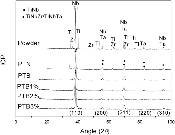
Figure 1 shows the X-ray diffraction pattern of the original powder and sintered porous samples. As can be seen, the characteristic peak of the porous Ti–Nb–Ta–Zr is broader than that of the starting powder. Moreover, there is no obvious impurity peak in sintered porous samples. The reason is that the pore-forming agent has been completely decomposed and removed at low temperature. It does not participate in the sintering process, thus avoiding impurity pollution. It is worth mentioning that a small amount of ɑ Ti (35.097°, 62.965°) and Zr (48.376°) element peaks can be observed in the diffraction pattern of the specimen sintered with unmilled powder (as shown in PTN), whereas only the beta phase (38.8°, 56.06°, 70.284°, 83.311°, and 95.994°) can be seen in the specimen sintered with ball-milled powders of different PCAs. As shown in PTB-PTB3%, the diffraction peak spectrum becomes sharper and broader with an increase in the amount of the PCA. This is because the powder size decreases with an increase in the amount of PCA during ball grinding, which is more conducive to diffusion in the sintering process. In addition, it should be noted that the atomic radius of Zr (2.16 Å) or Ta (2.09 Å) is larger than that of Ti (2 Å) and Nb (2.08 Å), and Zr or Ta could dissolve into the TiNb matrix and cause the expansion of the lattice of the alloy, thus leading the peak position to shift to the lower angle.
XRD diffraction profiles of mixture powder and sintered porous specimen of PTN, PTB1%, PTB2%, and PTB3%.

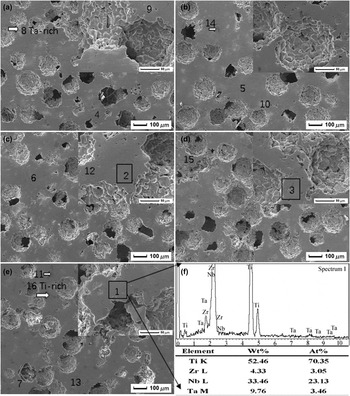
Figure 2 demonstrates the SEM images of porous Ti–Nb–Ta–Zr with 40% space-holder of 100–154 μm. Porous Ti–Nb–Ta–Zr has a three-dimensional connected open-pore structure, and its pores can be divided into two types: one is the macroscopic pores (macro-pores) with 35–200 μm (the size suitable for the growth of bone cells). The shape of the macro-pores formed by the volatilization of a spherical space-holder is close to that of spheroids, and the pore wall is relatively smooth. Some abnormally enlarged macro-pores may be caused by the agglomeration of some space-holders. The other is isolated approximately spherical micro-pores (<13 μm) distributed on the wall of the macro-pore. In the beginning of this sintering process (1200 °C for 2 h), micro-pores caused by shrinkage of particles remain irregular because the raw powders are fine (≤45 μm) and the migration mechanism of materials in this stage does not occur alone, but exists simultaneously in volume diffusion, surface diffusion, and grain boundary diffusion. In the final stage of sintering, the isolation, spheroidization, and shrinkage of micro-pores occur by means of volumetric diffusion mechanism.
SEM micrograph of (a) PTB, (b) PTB1%, (c) PTB2%, (d) PTB3%, (e) PTN, and (f) EDS in area 1.
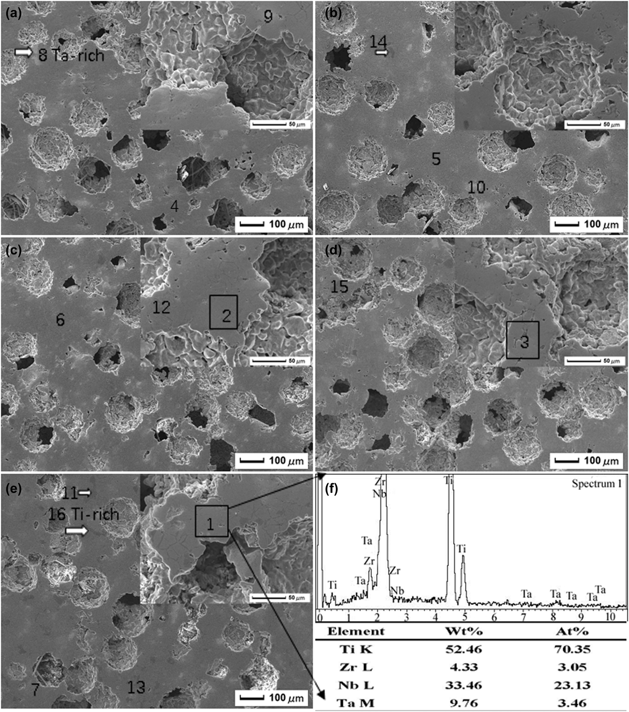
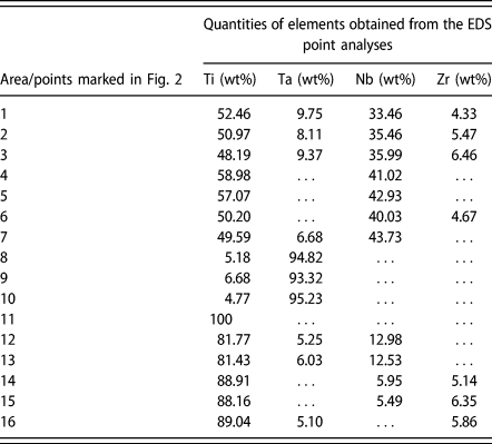
In Fig. 2, the composition of alloys, over areas 1–3, is close to the designed value Ti35Nb5Ta7Zr. Points 4–7 are marked on the β-phase regions, points 8–10 are marked on the light Ta-rich regions, and points 11–16 are marked on the black Ti-rich regions. Combined with X-ray diffraction patterns (Fig. 1) and EDS results (as shown in Fig. 2(f) and Table I), the light Ta-rich and black Ti-rich phases distribute uniformly in the grain β TiNb (Zr/Ta) matrix. The amount of the second phase in PTB is lower than that in PTN. As the PCA increases, the Ta-rich and Ti-rich phases reduce.
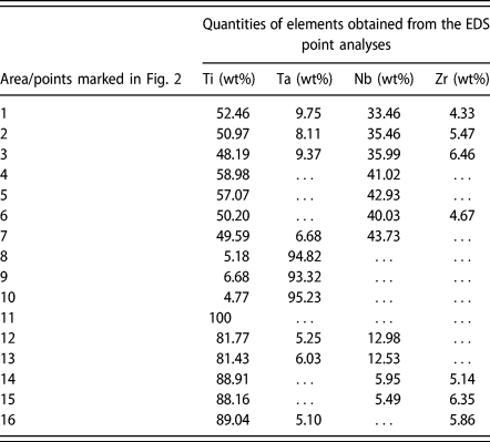
Chemical compositions of the as-sintered porous TNTZ alloy and the EDS point analyses carried out on the points marked in Fig. 2.
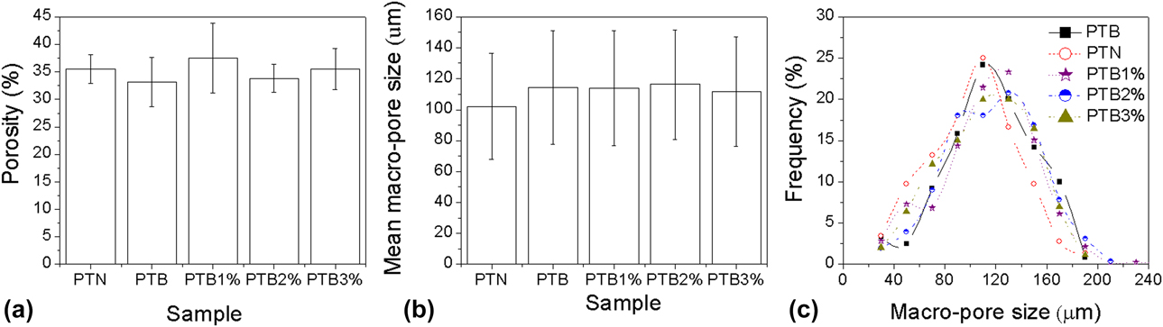
The relationship between porosity and the amount of PCA is shown in Fig. 3(a). The porosity of the porous Ti–Nb–Ta–Zr alloy using a 40% space-holder of 100–154 μm is approximately 35%, and its value does not change regularly with the change in the content of the PCA; that is, the addition of the PCA has no obvious influence on the porosity of the sample. The reason why the porosity of the sample is lower than that of the designed space-holder may be the agglomeration of the space-holder and the shrinkage of the pores of the sample during sintering.
Effect of PCA on the porosity (a), macro-pore size, (b) and distribution (c) of porous Ti–Nb–Ta–Zr.
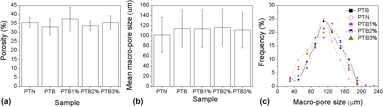
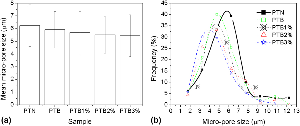
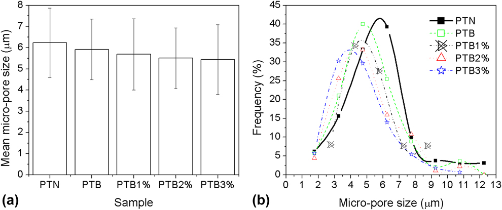
Figures 3(b) and 3(c) presents the macro-pore size and distribution of porous Ti–Nb–Ta–Zr using a 40% space-holder of 100–154 μm. The mean size of macro-pores is 110 ± 35 μm. The content of the PCA has no obvious effect on the macro-pore size and its distribution. Differently, the mean size of micro-pores with 2–13 μm, as shown in Fig. 4, decreases with the increase in the content of the PCA. This result is consistent with the microstructure shown in Fig. 2.
Micro-pore size (a) and distribution (b) of porous Ti–Nb–Ta–Zr.
Compressive property
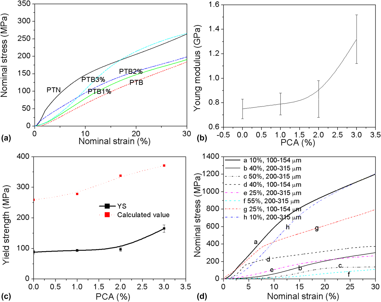
The compressive stress–strain curves of porous Ti–Nb–Ta–Zr alloys with different PCAs and space-holders (compared in Fig. 5) present excellent plastic deformation before 30% strain. It can be seen from Figs. 5(a) and 5(b) that the Young’s modulus of PTN is higher than that of PTB. Based on the Young’s modulus and strength of porous Ti–Nb–Ta–Zr produced by different mixed element powders shown in Figs. 5(b) and 5(c), as the content of the PCA increased from 0 to 3% (with the space-holder remaining the same), the Young’s modulus and yield strength increase from 0.8 to 1.3 GPa and from 88 to 165 MPa, respectively. It is related to the decrease in micro-pore and grain sizes [Reference Li and Lu21].
Compressive stress–strain curves (a), Young’s modulus (b), and yield strength (c) of PTB with different PCAs; stress–strain curves (d) of PTBA3% with different space holders.
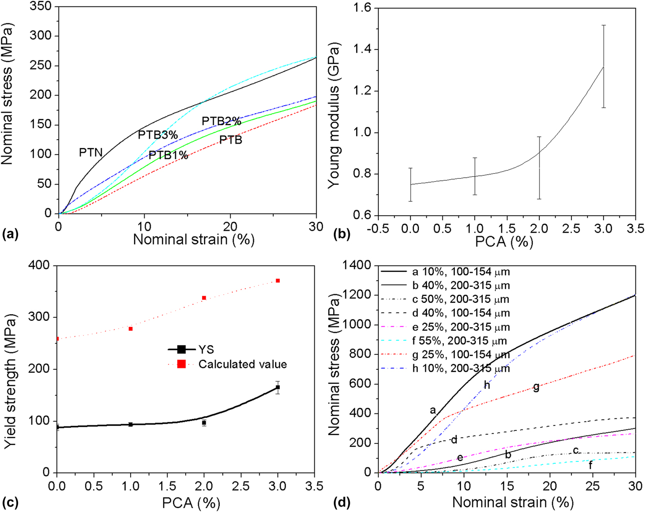
The porosity and macro-pore size of porous Ti–Nb–Ta–Zr alloys increase as the volume and size of the space-holder increase, thus weakening the Young’s modulus and strength. This is in accord with the results of the porous Ti produced by the same method in Refs. Reference Li, Lu, Hou and Teng34 and Reference Li, Wang and Lu35. Taken from Fig. 5(d), as the space-holder size is 200–315 μm, the Young’s modulus of porous Ti–Nb–Ta–Zr decreases from 6.2 to 0.8 GPa with an increase in the volume of the space-holder from 10 to 50%. When the volume of the space-holder is larger than 25%, the compressive stress–strain curves exhibit three stages (linear elastic region, long yield plateau stage, and final densification stage), as shown in Fig. 5(d), which is consistent with the trend of a porous metal under compression [Reference Li, Wang and Lu35].
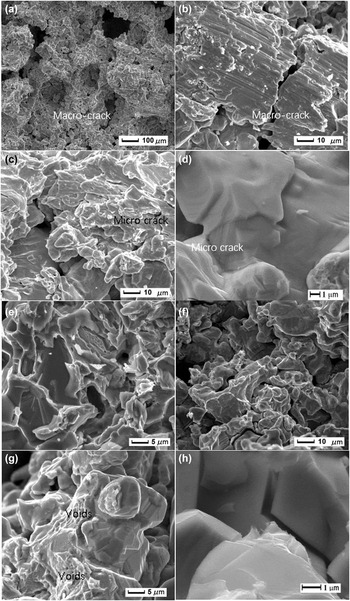
The compressed specimen sintered with 3% PCA balled powders is drum-shaped and has macro-cracks caused by cavitation and wall fracture during compression. The compressive tractography for the specimen presented in Figs. 6(a)–6(d) exhibits the macro-cracks in weak macro-pore walls and secondary cracks initiated from micro-pores. Different cleavage cracks can be connected by cleavage steps, fan-shaped cleavage, and feathery and smooth cleavage surface in Figs. 6(e) and 6(f). Voids of different sizes and shapes can also be seen in Fig. 6(g). Therefore, the fractured structure shown in Fig. 6 consists of cleavage fracture and ductile fracture with dimples in the porous Ti–Nb–Ta–Zr alloy.
SEM fractography of the PTB3% under compression showing: (a), (b) macro-cracks, (c), (d) micro-cracks, (e), (f) cleavage facets, (g) micro-voids, and (h) secondary crack along grain boundary.

Discussion
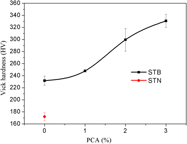
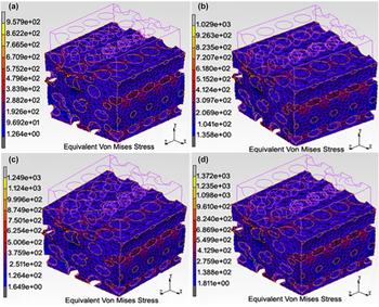
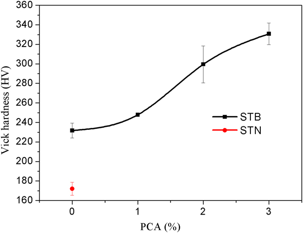
Combined with the effect of grain size and micro-pore size on the mechanical properties of solid Ti–Nb–Ta–Zr without macro-pores [Reference Li and Lu21], similar to the cell edge materials of porous Ti–Nb–Ta–Zr produced by the same method, microhardness test was used in this study to investigate the strength of cell edge materials. As can be seen from Fig. 7, increasing the amount of PCA (A) improves the Vickers hardness of sintered samples from 232 ± 7.5 to 331 ± 11. According to the results of Figs. 3 and 3(d), porous models with 35% porosity and 110 μm macro-pore size were constructed as shown in Fig. 8. The maximum equivalent Mises stress was obtained as 958–1372 MPa, which is higher than the strength of solid Ti–Nb–Ta–Zr (765 MPa) produced by the same procedure but without space-holder. By calculating, the theoretical strength of the porous model [Fig. 5(c)] is also higher than the experimental value of Ti–Nb–Ta–Zr. The first reason is that the strength value comes from Vickers hardness representing the tensile strength [36], which is higher than the compressive yield strength (σ0.2) of metal materials. In addition, the microhardness in this study was measured on the porous alloy’s skeleton, while the impact of Ti-rich and Ta-rich phases was neglected. According to Ref. Reference Yuan, Hou, Li, Hao, Yang, Zhang and Zhu37, these second phases may affect the ductility of the mesh struts of the porous sample. Moreover, the cell wall curvature and corrugations, stepped surface, nonuniform pore distribution, and micro-pores in the cell edge (Fig. 2) may result in local heterogeneities and stress concentrations, which then degrade the stiffness and strength, just like the stress distribution and localized deformations (as shown in Fig. 8) caused by a nonuniform macro-pore structure.
Effect of PCA on the Vickers hardness of matrix in porous Ti–Nb–Ta–Zr.
Stress distribution of the porous Ti–Nb–Ta–Zr model based on the feature of (a) PTB, (b) PTB1%, (c) PTB2%, and (d) PTB3%.

The effect of porosity on the yield strength and Young’s modulus of porous Ti–Nb–Ta–Zr can be analyzed by using the Gibson–Ashby model [Reference Gibson and Ashby38]:
 $${\sigma / {{\sigma _0}}} = C{\left( {1 - \varepsilon } \right)^t}\quad ,$$
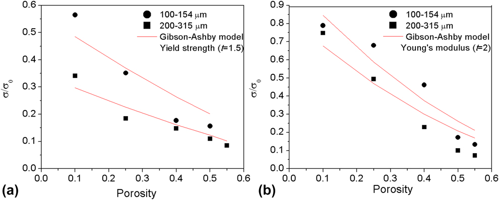
where C is the material constant from the data of porous metals. When t is 1.5, σ and σ0 represent the compressive yield strength of the foam and solid material without macro-pores, respectively. When t is 2, σ and σ0 are the Young’s moduli of the foam and solid material, respectively. In this study, σ0 for the yield strength (or Young’s modulus) is 1055 MPa (or 8.24 GPa), obtained from bulk samples by the same powder metallurgical method without space holder.
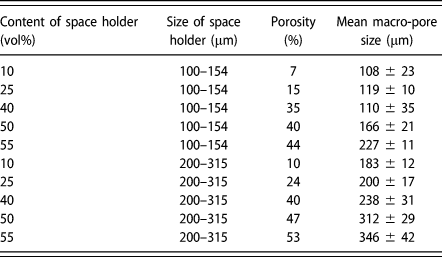
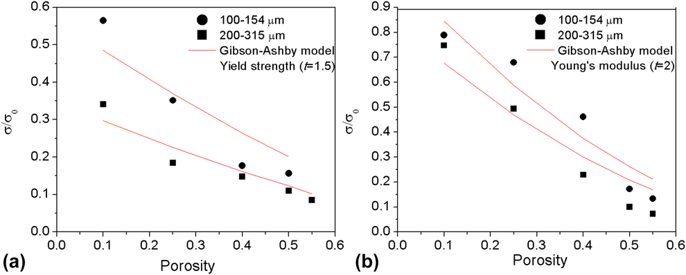
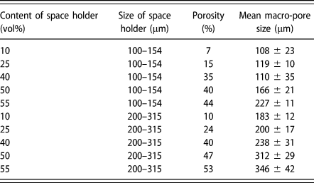
Submitting the experimental value of the porous Ti–Nb–Ta–Zr alloy into Eq. (1), as seen in Fig. 9, the parameters of C for yield strength (or Young’s modulus) decrease from 0.56 ± 0.06 to 0.35 ± 0.03 (or from 1.04 ± 0.08 to 0.83 ± 0.08) as the theoretical macro-pore size increases from 100–154 μm to 200–315 μm. The value of C is near to the predicted value of 0.3–1 [Reference Liu, Liang, Gu and Wang39], and the trend for this is consistent with the result of the porous Ti produced by the same method in Ref. Reference Li, Wang and Lu35. Moreover, the experimental data agree well with the Gibson–Ashby model as the theoretical porosity and pore size increase. This is mainly because the interconnected pore structure which depends on the porosity and pore size contributes to the bending strut in the Gibson–Ashby model, thus influencing the stress and strain distribution, such as localized deformations and reduced stiffness of the porous Ti–Nb–Ta–Zr as shown in Figs. 7 and 8. The allowable deviation by fitting is related to the difference between the volume or size of the space holder and real porosity and size (as shown in Table II).
Relationships between (a) yield strength, (b) Young’s modulus, and the pore structure of porous Ti–Nb–Ta–Zr combined with the Gibson–Ashby model.
Porosity and pore size of porous Ti–Nb–Ta–Zr with deferent space holder.
It is worth mentioning that the compressive stress–strain curves of the porous Ti–Nb–Ta–Zr show a larger strain (>30% before the plateau stage) than the traditional sintered porous metal with a similar pore structure, such as porous Ti (15%) and porous Ti6Al4V (10%) [Reference Li, Wang and Lu35, Reference Jorgensen and Dunand40]. It indicates that the macro-pore shape is distorted by the bending and collapse of the pore wall, as shown in Fig. 6. In addition, macro-cracks generate subsequently around the macro-pores, and occur preferentially in the macro-pore wall with the largest stress concentration, as shown in Fig. 8. As the stress increases, the cracks expand in the direction controlled by the maximum stress and in the route with the minimum resistance (along grain boundary or micro-pores as shown in Fig. 6). If the propagation passes through micro-pores, macro-cracks will generally expand with the help of the micro-pores, while small micro-cracks may stop growing due to the micro-pores. This shows that most energy of crack propagation is absorbed by the thick micro-pore wall, thus preventing the propagation of micro-cracks. Large macro-cracks can lead to the fracture of the pore wall and collapse of pores. Meanwhile, crack initiation and propagation occur successively in the secondary stress concentration area. Therefore, the stress platform characteristics presented in Fig. 5 appear during the compression process. Based on the points discussed earlier, it can be inferred that the results of the microstructure analyses are evidently in line with the results of the mechanical properties and fracture analyses.
The Young’s modulus of the porous Ti–Nb–Ta–Zr alloy ranging 0.8–1.3 GPa is close to 0.01–3 GPa for the trabecular bone, while the compressive yield strength ranging 88–165 MPa is much higher than 2–7 MPa for the trabecular bone [Reference Goldstein41] and sintered porous Ti or Ti–15Mo–5Zr–3Al [Reference Wen, Mabuchi, Yamada, Shimojima and Asahina28, Reference Niu, Bai, Qiu and Wang42, Reference Nomura, Kohama, Oh, Hanada, Chiba, Kanehira and Sasaki43]. It shows that the present porous Ti–Nb–Ta–Zr has potential application for trabecular bone implants. With respect to the load-bearing implant, one of the significant factors is enough mechanical strength to resist handling during implantation and in vivo loading [Reference Takemoto, Fujibayashi, Neo, Suzuki, Kokubo and Nakamura44]. Therefore, Ti–Nb–Ta–Zr with a porous structure and a compressive yield strength of 88–165 MPa, close to 76–192 MPa in porous Ti fabricated by casting and acid corrosion [Reference Taniguchi, Fujibayashi, Takemoto, Sasaki, Otsuki, Nakamura, Matsushita, Kokubo and Matsuda30], can be applied to trabecular bone prosthesis or as bone substitutes for spinal fusion.
Conclusions
The microstructure, mechanical properties, and fracture behavior of the as-sintered porous Ti–35Nb–5Ta–7Zr with <55% porosity and 100–400 μm macro-pore size prepared by the space-holder method are evaluated. The key concluding remarks of this study are outlined as follows:
(1) The alloy consists mainly of the β matrix, but with a few Ta-rich and Ti-rich phases. The micro-pore size decreases with an increase in the amount of the PCA, which has no obvious effect on the porosity and macro-pore size formed by the space holder method.
(2) As the content of the PCA increased from 0 to 3%, the Young’s modulus and yield strength increased from 0.8 GPa to 1.3 GPa and from 88 MPa to 165 MPa, respectively. As the volume and size of the space holder increased, the Young’s modulus and strength of the porous alloy decreased in the Gibson–Ashby model.
(3) The porous Ti–Nb–Ta–Zr alloy fails mainly because of the cleavage and ductile fracture with some dimples. The resultant compressive moduli of the samples vary in the range of 0.6–6.5 GPa, close to that of the trabecular bone.
Materials and methods
Preparation of Ti–Nb–Ta–Zr alloy sample
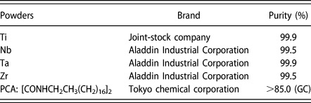
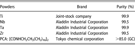
Commercial process control agent (PCA: [CONHCH2CH3(CH2)16]2), space holder (PMMA: polymethyl methacrylate), and elemental metal powders with particle size of ≤45 μm, such as Ti, Nb, Ta, and Zr, were used as raw materials. The details are listed in Table III. The metal powder mixture with a nominal composition of Ti–35Nb–5Ta–7Zr was mixed for 5 h under the protection of vacuum (10 Pa−1) and argon in a planetary ball milling machine. The weight ratio (balls to powder) was 10:1 and the rotation speed was 200 rpm. The milling media was composed of 304 stainless steel balls of 1 mm diameter. The PCA (0, 1, 2, and 3 wt%) and spherical PMMA particles (10, 25, 40, and 50 vol%) in ranges of 100–154, 154–200, 200–315, and 315–400 μm were separately added into an agate mortar prior to mixing.
Detailed information of raw materials.
To reduce the micro-pores [Reference Li, Lu, Hou and Teng34, Reference Li, Wang and Lu35], the mixture powders were then consolidated under pressure of 500 MPa for 30 s. The green compacts were heat-treated at 250–450 °C for 5 h to remove the space holders and then sintered at 1200 °C for 2 h in a vacuum diffusion melting furnace (HZK-40) at a heating/cooling rate of 10 °C/min. The whole sintering process was under 10−3 Pa.
A series of porous Ti–Nb–Ta–Zr alloys sintered with unmilled elemental powder (marked as PTN) and with ball milled elemental powders of different PCAs (marked as PTB-PTB3%) were fabricated by using 40% space holder of 100–154 μm. Based on Ref. Reference Li, Lu, Hou and Teng34 and Table II, the porous specimen with <55% porosity and 100–400 μm macro-pore size controlled by the content and size of the space holder were produced by using ball milled elemental powders with 3% PCA.
Characterization and evaluation of Ti–Nb–Ta–Zr alloy powders and sintered porous samples
The microstructure of the porous samples was observed by scanning electron microscopy (SEM) (JSM-6360LV), energy-dispersive spectroscopy (EDS) (INCA), and X-ray diffraction (XRD) (EMPYREAN) using Cu Kα radiation (40 kV, 40 mA) at a scanning rate of 2°/min. Pore size distribution was measured by quantitative metallography. Porosity was obtained by weight and apparent volume of the specimen. Open and closed porosity was determined by weight measurements prior to and after dipping the samples into water under a vacuum condition.
The compressive properties of the porous samples were studied using a desk-top mechanical tester (AG5000-A) at a constant strain rate of 0.001/s. A compression cage with hard-metal platens was used to assure parallelism, with an extensometer attached to the platens to determine the elastic modulus. The compressive strength of the porous Ti–Nb–Ta–Zr alloy was taken from the plateau region of the curves. The 0.2% offset method was used to determine the yield strength of the porous samples. At least three measurements were carried out under the same conditions, and the mean values were calculated. For each group of samples, compression testing was carried out on cylinder-shaped samples with 10 mm diameter.
To examine the effect of macro-pore structure on the onset of local deformation in the neighbors of the macro-pores, the stress distribution on the porous TNTZ with only macro-pores was analyzed by finite-element modeling (FEM). The pore distribution ratio, pore anisotropic rate, and relevant structural parameters of the porous TNTZ with a porosity of 35% and pore size of 110 μm were obtained by 2D metallography and using a 3D video microscope (LJ-X8000). The 3D cell block and finite element meshes were created by Pro/E software. The stress distribution of the porous TNTZ was analyzed by Matlab software. The distributed static load was equivalent to the yield stress of the porous TNTZ samples with different PCAs. The stress concentration factor of pores in the porous TNTZ was calculated by the formula in Ref. Reference Li, Wang and Lu35. A linear-elastic constitutive formulation was still specified for the porous TNTZ with a Poisson ratio of 0.3.
Vickers hardness (HV) measurements were carried out on the pore walls of the polished surface of the samples using a microhardness testing machine (FM700). A load of 100 g was applied for 15 s (dwell time). Eleven different measurements were performed for each sample group, and the maximum and minimum values were not taken into calculation.
Acknowledgments
This work was supported by the “1331” Innovation Team of Jinzhong University (jzxycxtd2019008) and a research project under Grant No. 201801D221095 from the Natural Science Foundation of Shanxi Province (CN).