Introduction
In modern-day communication, the wireless body area network (WBAN) is a promptly developing technology due to larger application areas specifically in wellness, security, and sports [Reference Zhou, Fang and Jia1]. The IoT and 5G communication will further enhance the demand for compact wearable antennas for applications related to lifestyle [Reference Paracha, Rahim, Soh and Khalily2].
The high data rate, enhanced channel capacity and low latency are the vital requirements for an expeditious communication system where the MIMO antenna fulfills these requirements compared to a single-element antenna. The antenna should be compact in size for wearable and portable devices where the antenna can be easily accomplished in these devices with minimum space. Maintaining the isolation in the compact antenna is an arduous task for researchers and endeavors are being done to achieve high isolation in compact MIMO antennas. The diverse technologies and structures are being proposed for decoupling to enhance the port isolation based on the stubs [Reference Dey, Pattanayak, Mitra and Arif3–Reference Kumar, Nandan, Srivastava, Kumar, Singh, Marey, Mostafa and Kanaujia8], neutralization line [Reference Biswas and Chakraborty9], meta-surface [Reference Wang, Zhao, Cai, Zheng and Yin10], meander line [Reference Singh, Kanaujia, Kumar, Srivastava and Kumar11, Reference Roy, Ghosh, Pattanayak and Chakarborty12], metamaterial [Reference Roy and Chakraborty13], slots [Reference Anbarasu and Nithiyanantham14, Reference Sufian, Hussain, Askari, Park, Shin and Kim15] and EBG [Reference Kumar, De and Jain16] where these decoupling structures are placed between antenna elements which increase the antenna size as well as impractical in wearable and portable application due to complex and rigid structure.
In [Reference Dey, Pattanayak, Mitra and Arif3], circular radiators are designed for UWB flexible antenna whereas in the ground E-shaped decoupling structures are accomplished for isolation enhancement. In [Reference Biswas and Chakraborty9], the MIMO antenna is presented with two circular radiators and a neutralization line is designed in between radiators which are responsible for isolation enhancement. In [Reference Biswas and Chakraborty4], a combination of I and T-shaped stubs are incorporated in the bottom plane to diminish the surface current between rectangular-shaped radiators. In [Reference Wang, Zhao, Cai, Zheng and Yin10], a meta-surface is proposed using SRR to improve isolation between two radiators where the SRR unit cell is demonstrating the metamaterial characteristics. In [Reference Radhi, Nilavalan, Wang, Al-Raweshidy, Eltokhy and Aziz5], a planar-modified T-shaped metallic stub is incorporated between two circular radiators to diminish the surface current. In [Reference Singh, Kanaujia, Kumar, Srivastava and Kumar11], a T-stub along with two rectangular rings is accomplished in the ground plane and a meander line between radiators is used to improve the isolation. In [Reference Kumar, De and Jain6], isolation is enhanced in a miniaturized antenna with an open stub and T-shaped decoupling structure in the ground. In [Reference Roy and Chakraborty13], metamaterial-inspired structures are used in the ground plane as well as in the top plane to enhance the isolation of wearable antennas. In [Reference Roy, Ghosh, Pattanayak and Chakarborty12], the ground plane is reformed with a zig-zag shape and the meander line between multiple slot radiators is used for isolation enhancement of flexible antenna. In [Reference Gupta, Kansal and Chawla7], inverted U-shaped decoupling is used to mitigate the surface current between the modified S-shaped radiators where the antenna is designed with the unconnected ground. In [Reference Kumar, Nandan, Srivastava, Kumar, Singh, Marey, Mostafa and Kanaujia8], two arc-shaped radiators are used in a flexible MIMO antenna with circular polarization where the modified T-shaped decoupling is used to alleviate the correlation between radiators. In [Reference Anbarasu and Nithiyanantham14], a two-element antenna is designed for smartwatch applications where antenna positioning and slots in the ground plane are responsible for improved isolation. In [Reference Kumar, De and Jain16], two H-shaped EBGs with metamaterial characteristics is used for isolation enhancement of the UWB antenna. In [Reference Sufian, Hussain, Askari, Park, Shin and Kim15], a four-port orthogonally placed MIMO antenna is designed for 5G (Sub-6 GHz) applications. The slots in the ground plane and multiple shorting pins are diminishing the surface current movement and isolation enhancement is achieved. In [Reference Jha, Kumar, De and Jain17], a simple decoupling is discussed by increasing the ground plane vertically between the two radiating elements which enhances the isolation of the MIMO antenna. In [Reference Sharma, Kumar, De and Jain18], a two-port MIMO antenna is discussed with textile material based on reference [Reference Jha, Kumar, De and Jain17] where the edge-to-edge distance between antenna elements is kept high. Due to less ground height, defects in ground and higher edge distance between elements, isolation enhancement is achieved in the antenna but found unstable at lower frequencies.
According to the literary analysis of WBAN and portable applications, the textile MIMO antenna is designed with the following technical contributions.
(a) The compact antenna is designed with a flexible textile material having a physical size of 24 × 24 mm2.
(b) The Y-shaped decoupling and shorting pins with the parasitic element between two radiators improves the isolation up to 14 dB.
(c) The open-ended slots generating the miniaturization property in the MIMO antenna where the electric length of MIMO is 0.3λ 0 × 0.3λ 0.
(d) The SAR analysis is carried out using the phantom wrist model which assures the minimum radiation effects and it can be used in wearable applications.
Designing of MIMO antenna
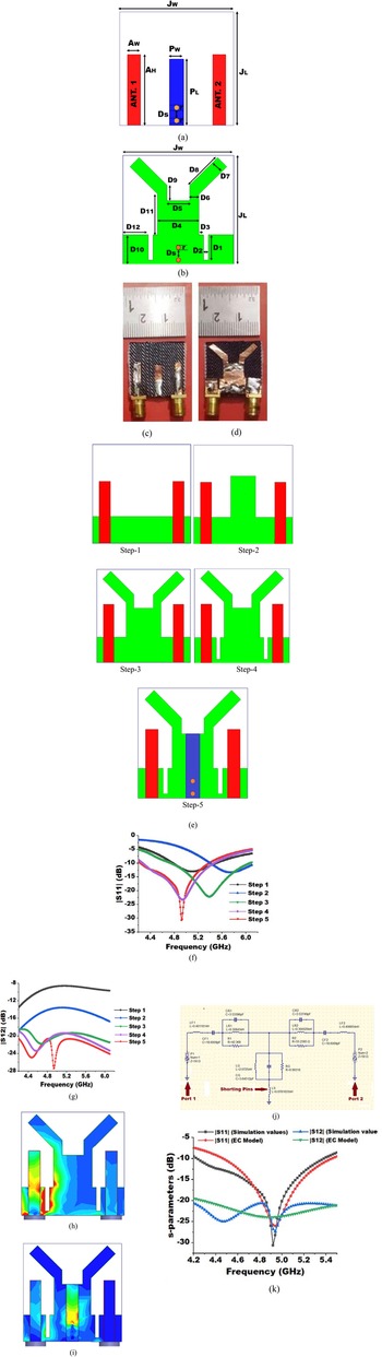
The proposed textile MIMO antenna is designed with flexible jeans material. The dimensions of the MIMO antenna are shown in Figs 1(a) and 1(b) whereas the hardware prototype is demonstrated in Figs 1(c) and 1(d). The substrate material is having dielectric constant (ɛr) of 1.7 and a loss-tangent (tan δ) of 0.022 with 1 mm of thickness. The dimensions details of two port antennae in mm are as follows: AW = 2.7, AH = 15, PW = 3, PL = 14.5, JW = 24, JL = 24, r = 0.5, Ds = 2.75, D 1 = 5.5, D 8 = 6, D 2 = 1, D 5 = 5, D 3 = 1, D 12 = 5.5, D 6 = 2, D 10 = 6.5, D 4 = 9, D 7 = 2, D 9 = 3.5, D 11 = 9.
(a) Dimensions associated with the Top plane (b) dimensions associated with the bottom plane of the proposed MIMO antenna (c) front view of hardware prototype (d) back view of hardware prototype of textile MIMO antenna (e) development steps of textile antenna (f) obtained variations in |S 11| (g) obtained variations in |S 12| associated with the all design steps (h) surface current distribution without shorting pins in the textile MIMO antenna (i) surface current distribution with shorting pins in the textile MIMO antenna at 4.94 GHz frequency (j) designed equivalent circuit model of textile MIMO antenna using QUCS tool and (k) obtained variations in s-parameters through the simulation work (HFSS) and from the designed EC model (QUCS).

The five evolution steps are considered in the designing of two-port textile antenna as illustrated in Fig. 1(e). The 10 dB impedance bandwidth (IBW) of all evolution steps are illustrated in Fig. 1(f) and the isolation (|S 12|) improvements are depicted in Fig. 1(g).
In step 1, two microstrip feed are used as a radiator with a partial ground of height 6.5 with 2.7 mm feed width to achieve 50 Ω impedance matching. The obtained 10 dB IBW is varying from 4.78 to 5.1 GHz with maximum isolation of 9.2 dB. In step 2, the ground plane is increased vertically [Reference Jha, Kumar, De and Jain17] and the operating bandwidth shifts from 5.75 to 6.08 GHz whereas the maximum |S12| is achieved up to 16 dB. In step 3, the ground plane is modified into a Y-shaped structure to diminish the surface current effectively between antenna elements and to enhance the isolation. The |S 11| in this step varies from 4.75 to 6 GHz whereas |S 12| varies from 19.1 to 20.85 dB. In step 4, two symmetric open-ended slots are created in the ground to advance the impedance matching in the antenna and the existing 10 dB IBW shifts toward the lower frequency thus miniaturization property is obtained in the presented work. The |S 11| varies from 4.25 to 5.26 GHz and |S12| is varying from 19.1 to 23.3 dB. In Step 5, two shorting pins are introduced with parasitic elements which increase the electric extent of the ground plane and diminish the current movements effectively between antenna elements. A parasitic element is integrated with a radiator and connected with a ground plane using two shorting pins which modify the lumped elements and facilitate the movement of surface current from the ground plane toward the parasitic element through shorting pins. With the combination of shorting pins and parasitic elements in the textile MIMO antenna, up to 8 dB isolation improvement is achieved. The final 10 dB IBW is obtained from 4.24–5.38 GHz with 27.8 dB maximum port isolation. The current distribution effects without shorting pins and with shorting pins are shown in Figs 1(h) and 1(i), which demonstrates the working of shorting pins by amending the current movements from the ground plane toward the parasitic element and diminishing the current association between the two ports.
The equivalent circuit (EC) model of the MIMO antenna is designed using the QUCS tool with the help of lumped components as shown in Fig. 1(j) and the comparison of obtained results of s-parameters using QUCS model and the simulated values of HFSS tool is depicted in Fig. 1(k). In the circuit, a 50 Ω feed line is connected with the inductor (LF1) and capacitance (CF1) for port 1 whereas LF2 and CF2 are for port 2. A resonant network is created using parallel capacitance, inductance and resistance (CR1, LR1, R1) for port 1 and similarly CR2, LR2 and R2 for port 2. To signify the effects of shorting pins and inductance, LS (inductance) is connected with the ground plane and finally, the effect of the parasitic element is obtained with the help of parallelly connected LG, CG and RG lumped components. The values of all these components are given in Table 1.
Values of the lumped component in EC model.

Parametric study of MIMO antenna
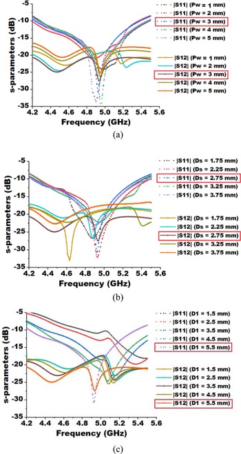
To insight into more possibilities in the antenna results, the pertaining dimensions of the antenna are examined. First, the width of the parasitic stub (Pw) is changed from 1 to 5 mm to observe the changes in the s-parameters. The impedance matching of the antenna remains almost same with a minor variation in the resonance frequency. The change in the width of parasitic affects the isolation between ports meaningfully. The optimum results are obtained with the parasitic width of 3 mm as depicted in Fig. 2(a). The spacing between shorting pins is also amending the movement of current and when the distance between two shorting pins is altered, it is changing the isolation as well as impedance matching of the MIMO antenna. The variations lead to the response of |S 12| above 20 dB which is undesirable. The 2.75 mm spacing is producing the most suitable output in the antenna as shown in Fig. 2(b). While reducing the length of open-ended slots leads to the sifting of |S 11| toward the higher frequency. The length of open-ended slots (D 1) is finalized at 5.5 mm considering the total length of the available ground plane. The variations in s-parameters are depicted Fig. 2(c).
(a) Variations in s-parameters while changing the width of parasitic stub (b) Variations in s-parameters while altering the spacing between shorting pins (c) Variations in s-parameters while changing the length of open-ended stubs in the proposed textile MIMO antenna.

Wearable analysis
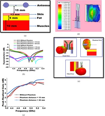
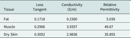
To investigate the on-body effects of textile antenna radiations, the wearable analysis is conducted using the three-layered (skin, fat and muscles) phantom wrist model. To analyze the antenna parameters under the presence phantom model, the width of the muscles layer, fat layer and skin layer is considered 10, 5 and 2 mm individually [Reference Sharma, Kumar, De and Jain18]. To examine the effect of the phantom model upon the antenna, it is kept behind the textile antenna at a standard distance of 20 [Reference Sharma, Kumar, De and Jain18] and 15 mm [Reference Sharma, Kumar, De and Jain19] respectively. On-body effect of the antenna is also observed by conducting the SAR analysis using the phantom model. The phantom model with antenna is illustrated in Fig. 3(a), where the s-parameters of the textile MIMO antenna in the presence of the phantom model at the different distance are depicted in Fig. 3(b). Small variations in s-parameters are observed in the textile antenna due to the coupling effect between the phantom model and the MIMO antenna, specifically at the higher frequencies. The realized peak gain is illustrated in Fig. 3(c) in the presence of the phantom model and up to 1 dB variations are observed at higher frequencies in the MIMO antenna. The SAR analysis is conducted using standard 0.01-Watt input power on 1 g standard human tissue. The material characteristic at 4.9 GHz of the human phantom model is given in Table 2 [20]. The maximum value of average and local SAR is obtained at 0.27 and 0.086 W/kg where it is under the permissible limit of SAR. The variations in the average value of SAR are depicted in Fig. 3(d). The 3D radiation pattern of the textile MIMO antenna in the presence of the phantom is depicted in Fig. 3(e).
(a) Proposed phantom model for textile antenna (b) variations in S-parameters with the different phantom distances (c) variations in S-parameters with the different phantom distances. (d) the variations in the average value of SAR (e) 3D radiation patterns of the textile MIMO antenna in the presence of phantom model.

The tissue characteristics of the human phantom model at 4.9 GHz

Results and discussion
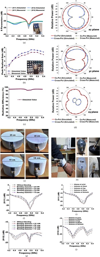
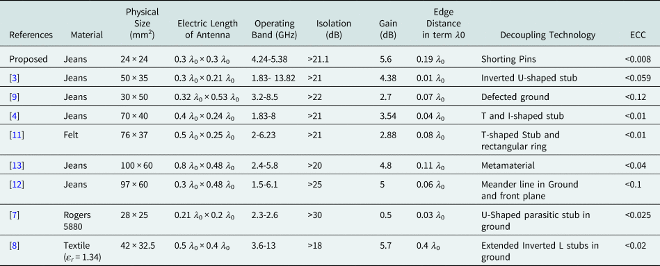
The HFSS-13 EM software is used to design and simulate the proposed two-port textile MIMO antenna and experimental results are completed using a vector network analyzer (Anritsu MS2025B). The antenna s-parameters are demonstrated in Fig. 4(a) where 10 dB |S 11| varies from 4.24–5.38 GHz with more than 21.1 dB isolation. The realized gain is illustrated in Fig. 4(b) where the simulated value of realized gain varies from 2.01 to 5.6 dB and the measured results have less than 0.6 dB variations. These deviations occur due to the environmental issues and losses associated with higher frequencies. The simulated radiation efficiency is obtained more than 92.5% as depicted in Fig. 4(c). The normalized radiation patterns of the proposed textile antenna are investigated at 4.90 GHz frequency at port 1 (port 2 is terminated with 50 Ω matched load) for all three planes and illustrated in Fig. 4(d) where the stable radiation is obtained in the end-fire direction. The comparative analysis of the proposed textile MIMO is done in Table 3 with recent works and reveals that the physical size of the antenna is compact with satisfactory MIMO parameters and can be used with wearable and portable devices within the limited space.
Experimental analysis of (a) s-parameters (b) realized gain of the textile antenna (c) simulated radiation efficiency of the textile antenna (d) the normalized radiation patterns at 4.90 GHz in x-z, y-z and x-y plane (e) antenna bending in the x-direction at different diameters (f) obtained |S 11| (g) obtained |S 12| at the different bending diameters (h) antenna positioning at different body parts (i) obtained |S 11| (j) obtained |S 12| at different on body positions.

Comparative analysis of the proposed wearable antenna with another recently published works

The bending analysis is carried out in the proposed textile MIMO antenna to validate the bending scenarios using the cylindrical foam substrate with different diameters as depicted in Fig. 4(e). The bending effects on s-parameters are shown in Figs 4(f) and 4(g) where minor variations are observed in the |S 11| and isolation |S 12| when the bending curvature is decreased from 25 to 10 cm. The resonant frequency shifts toward the lower frequency as the bending curvature is decreased.
Further, to analyze the wearable application, the on-body positioning of the proposed antenna is fixed at different body parts as illustrated in Fig. 4(h) and its s-parameters are shown in Figs 4(i) and 4(j). The reflection coefficients are analyzed by positioning the textile antenna at the helmet, cap, wrist, chest, and shoes. The minimal variations are found in s-parameters when the antenna is positioned at the cap, chest and wrist whereas the s-parameters changed slightly when the antenna is kept on shoes and helmets.
MIMO parameters
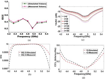
To achieve better diversity performance, high isolation and less correlation are vital necessities in the MIMO antenna. The envelope correlation coefficient (ECC) signifies the association between radiating elements and it also provides the analysis that how radiation patterns are affecting each other when they are operating alongside. ECC is calculated using far-field analysis with equation (1) [Reference Jha, Kumar, De and Jain21] considering the practical applications. The value of ECC is below the level of 0.5 as shown in Fig. 5(a). The XPR given in equation (1) is the cross-discrimination ratio between horizontal and vertical polarized power where Eθ, and Eφ, are the field components respectively and θ is varying from 0° to 180° and φ is varying 0° to 360 °. The diversity gain is calculated by using equation (2) [Reference Sufian, Hussain, Abbas, Lee, Park and Kim22] and illustrated in Fig. 5(b) and it is close to 10 dB. The value of the total active reflection coefficient (TARC) implies the incident power at the angle of θ and its effect upon radiated power. It is also useful in determining the bandwidth and efficiency in a better way. To calculate the TARC equation (3) [Reference Sufian, Hussain, Abbas, Lee, Park and Kim22] is used and it is illustrated in Fig. 5(c). The higher data rate in the MIMO antenna can be achieved with the improved channel capacity and by minimizing the losses in channels. Equation (4) [Reference Sufian, Hussain, Abbas, Lee, Park and Kim22] is used to calculate the channel capacity loss (CCL) and in the equation, ψ R represents the correlation matrix. Figure 5(d) demonstrates the obtained CCL and the obtained value is below 0.5 bits/sec/Hz.


Obtained MIMO parameters (a) ECC (b) DG (c) TARC (d) CCL of proposed textile MIMO antenna.

Conclusion
The proposed two-port textile MIMO antenna is designed using a flexible jeans substrate. The antenna is miniaturized with the help of two open-ended slots in the ground plane where a Y-shaped decoupling structure and two shorting pins with parasitic stubs effectively improve the isolation up to 27.8 dB. The antenna is examined using the wrist phantom model and an acceptable value of SAR is achieved for WBAN applications. The MIMO parameters of the two-port antenna are under the permissible limit and can be proficient for 5G, WLAN and wearable applications.
Financial support
No funding details are available.
Conflict of interest
The authors report no conflict of interest.
Data availability statement
All data are maintained in the manuscript.
 Pankaj Jha received B. Tech and M. Tech degree from Uttar Pradesh Technical University (Now AKTU), Lucknow, UP, India. He is persuing his Ph.D. from Shobhit Institute of Engineering and Technology, (NAAC “A” Grade, Deemed-to-be University) Meerut, India. His research area includes antenna designing for 5G communication, metamaterial inspired antenna, FSS for gain enhancement, wearable antenna and MIMO antenna. His research works are being published in reputed SCI/Scopus index journals.
 Anubhav Kumar received B. Tech and M. Tech from Uttar Pradesh Technical University (Now AKTU), Lucknow, UP, India. He is currently pursuing Ph.D. from Shobhit Institute of Engineering and Technology, (NAAC “A” Grade, Deemed-to-be University) Meerut, UP, India. He has published many SCIE/ESCI and Scopus indexed research papers in the reputed journal. His research interests include microstrip antenna, metamaterial inspired antenna, FSS, MIMO, wearable, EBG antenna and Image processing.
 Professor Asok De did his Ph.D. from Indian Institute of Technology, Kharagpur. He served as director in National Institute of Technology Patna and Durgapur. He served as a professor in Delhi Technological University (DTU), Delhi, India. Professor De has expertise in the all domains of RF and Microwave engineering. Professor De has published more than 240 research papers in reputed International and National Journals and conferences. He supervised more than 20 research scholars till now.