NOMENCLATURE
- CFD
-
Computational Fluid Dynamics
- HP
-
High Pressure
- IP
-
Intermediate Pressure
- LP
-
Low Pressure
- MPI
-
Message Passing Interface
- RANS
-
Reynolds-Averaged Navier-Stokes
Symbols
- η
-
efficiency
- T 0
-
total temperature, K
- m
-
mass flow rate, kg/s
- k
-
turbulent kinetic energy
- ω
-
turbulent eddy frequency
Subscripts
- cool
-
coolant stream
- main
-
main flow
- mix
-
mixed stream
- rim
-
rim seal leakage
1.0 INTRODUCTION
The main flow of expanding hot gases in turbines is three-dimensional, viscous, un-steady and exhibits various phenomena like secondary flow, transition, re-laminarization, shock boundary-layer interactions, and so on. In addition to the main flow, there are cooling flows and leakage flows in the turbine flow path. The cooling flows are essential to keep the metal temperatures within reasonable levels to achieve the desired life target. Leakage flows enter the main flow path through the gap between the stator and rotor assemblies and are required to prevent hot air ingestion into the regions of the disc and the secondary air system elements. The leakage flows fed near the platform of the rotor aerofoil are typically called the rim seal flows. Furthermore, there is a clearance between the tip of the rotor aerofoil and the casing of the turbine. In the case of shrouded rotor blades, this region of clearance is in the form of a seal with radial protrusions called ‘fins’. Some flow from the main flow path escapes through the tip clearance zone, and results in the development of tip leakage flow vortices. The axial gap between the stator and rotor in the turbine stage is fixed by considerations of aerodynamic stator-rotor interactions and forced response of the rotor because of the wakes shed from the stator. All these factors mentioned above influence the performance of the turbine; however, the turbine performance may also be impacted further by changes to the turbine operating conditions and geometry following an event such as a shaft failure.
Following the break of a shaft, whether the components on that shaft are free to move axially depends on the bearing arrangement for that particular engine. Typically, the turbine will be free to move because a roller bearing is installed to accommodate thermal expansion of the shaft. Assuming the turbine is left free to move, the axial force acting upon it, a combination of the secondary air system pressure differential acting on the disc, and the main gas path forces acting on the rotor blade moves the turbine rearward and into contact with downstream static structures. Since the turbine has been disconnected from the compression side, it is left free to accelerate. Should the speed exceed the burst margin, a hazardous event involving the release of high-energy debris may occur. From a compression system point of view, the rapid deceleration likely forces it into surge, which helps to limit the available power to the free-running turbine. The compressor is likely to surge within a few rotations of the compressor following the shaft break, while the turbine is expected to reach terminal speed in the region of 0.5–1s following the shaft break. A turbine overspeed analysis must account for all forms of energy input and extraction from the turbine, this analysis focuses on the ability of the turbine to extract power from the main gas path, quantifying performance as a function of axial movement. Such information can then be fed into an overspeed analysis accounting for all energy sources(Reference Haake, Fiola and Staudacher1). An accurate prediction of the terminal speed of a rotor during overspeed is required for introducing various design changes that may reduce the likelihood of an uncontained failure and for engine certification purposes.
The effect of leakage flows, tip clearance flows and axial gaps on the aerodynamic performance of the turbine stage has been studied in detail by various researchers. Blanco et al(Reference De la Rosa Blanco, Hodson and Vazquez2) studied the effect of leakage flows and of the upstream platform geometry in a cascade tunnel (also through numerical simulations) of a low-pressure turbine and concluded that the leakage flows lead to a strengthening of the end-wall flows in the rotor that consequently increase the rotor pressure losses. Popovic et al(Reference Popovic and Hodson3) described the flow structure of the leakage from rim seals and suggested methodologies to approach the rim seal design for better sealing from hot air ingestion and lower losses. Reid et al(Reference Reid, Denton, Pullan, Curtis and Longley4) developed a relation between the leakage flow rates and rotor pressure losses in an intermediate-pressure turbine stage. Paniagua et al(Reference Paniagua, Denos and Almeida5) carried out an experimental and computational study of the impact of leakage flows in a transonic High-Pressure (HP) turbine. His work provides details about the change in the flow features and rotor static pressure distributions. Rosic et al(Reference Rosic, Denton and Pullan6,Reference Rosic, Denton and Curtis7) describes the importance of modelling the tip leakage flows in multi-stage turbine calculations to accurately predict the performance parameters of the turbine, along with studying the influence of different shroud geometries on the flow behaviour in turbines. Palmer et al(Reference Palmer, Tan, Zuniga, Little, Montgomery and Malandra8) performed a number of steady and unsteady numerical calculations of flow in the tip seal and described the loss generation mechanisms because of the tip leakage flows. Yun et al(Reference Yun, Porreca, Kalfas, Song and Abhari9) performed a stereoscopic particle image velocimetry study in a two-stage shrouded turbine and described in detail the evolution and interaction of tip leakage flows with the main flow. Gaetani et al(Reference Gaetani, Persico, Dossena and Osnaghi10) experimentally analysed the flow field in a HP turbine stage for two different axial gaps and described the differences in the flow physics.
From the above-mentioned literature it can be noticed that previous work has focused on obtaining the aerodynamic effect of the leakage flows and axial gaps at nominal turbine operating conditions, with the goal of quantifying performance changes to provide design guidelines. However, the combined effect of the rim seal flow, tip leakage flows and change in the stator-rotor axial gap due to the rearward movement of the rotor configuration that occurs during an un-located HP shaft failure, has not been studied before.
In the present study an integrated, multi-disciplinary framework of structural, secondary air system and main gas path models is used to capture the consequent change in turbine performance at different displacements after failure. The downstream movement of the rotor results in a change in the geometry of the aerofoils, tip seals and rim seals. Changes in the geometry are obtained using structural analyses. The behaviour of the engine during the overspeed event results in a change in the rim seal flow, interacting with the main flow because of the secondary air system. The main gas path is modelled using steady Reynolds-Averaged Navier-Stokes (RANS) 3D Comptational Fluid Dynamics (CFD), while the secondary air system is modelled using a network of cavities, nozzles, restrictors and pipes, as well as 1D un-steady Euler equations. The structure and behaviour of the tip leakage flows also change because of changes in the tip seal geometry. This is also modelled using high-fidelity 3D CFD. More details of the exact methodology adopted in this work are given in the next section.
2.0 METHODOLOGY
A typical axial flow, rising line HP turbine stage consisting of a highly loaded, transonic stator, and a shrouded rotor blade is considered in the present study. The stator aerofoil is modelled with coolant ejection from the trailing-edge slot. The rotor blade is modelled with the tip seal near the shroud region and the rim seal in the hub platform region. The tip seal consists of two fins extending to different radii because of the rising line design of the rotor. The casing of the seal has a three-step arrangement to bridge the different radii due to the incline. The geometry of the tip seal is shown inset in Fig. 1. The rim seal is essentially a gap between the rotor platform and the stator lip projection. Additionally, a rotor blade model without the rim seal and the tip seal is also analysed as a ‘clean’ configuration to enable a comparison to quantify the effect of the leakage flows at the nominal condition.
Computational domain for no-displacement and 15-mm axial displacement cases showing details of the tip seals and the rim seals.

The downstream vane is also considered to be a part of the aerodynamic study to ensure appropriate circumferential variation of static pressure downstream of the rotor and to study the impact of the change in the aerodynamic performance of the rotor on the flow behaviour in the downstream vane. The flow conditions for the rim seal flows are obtained from the secondary air system model, discussed subsequently. Turbine performance is analysed based on the underlying assumption that the turbine aerodynamics are quasi-steady. While this most definitely is not the case, an initial estimation of the effects of axial movement can be obtained, along with the underlying causes and reasons, on the terminal speed of the turbine rotor.
The effect of the rearward movement of the rotor is studied by considering two additional cases in which the rotor configuration with the seals and platforms is axially displaced 10 mm and 15 mm in the downstream direction. A comparison of the un-displaced configuration and the configuration with 15 mm displacement is shown in Fig. 1. The axial displacement of the rotor results in an increase in the area between the fins and the casing in the tip seal, an increase in the gap between the stator lip and the rotor platform in the rim seal and damage to a portion of the rotor blade due to impact with the downstream vane hub platform. In this instance, the blade has a portion removed by the vane hub platform, with the vane hub platform remaining in place. The extent of damage in the rotor blade is obtained from a structural analysis of the rotor sub-assembly using LS-DYNA(Reference Psarra, Pachidis and Pilidis14,Reference Gonzalez and Pachidis15) , simulating the overspeed behaviour of the turbine. The aerodynamic performance is analysed for these two specific displacements because, it is near a displacement of 10 mm that the increase in area near the tip seals is significant, and beyond a displacement of 15 mm the damage to the rotor blade is quite high. Therefore, aerodynamic snap-shots of the turbine performance obtained from 3D RANS analyses at these two displacements, with appropriate evolution of flow conditions at the rim seals, can provide a useful insight into the physics of the flow in the axially displaced case as compared to the un-displaced case.
2.1 Grid generation
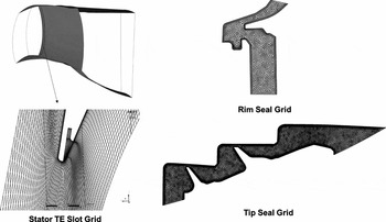
The computational domain under investigation for the present study includes the stator with trailing-edge slots, rotor, tip seals, rim seals and the downstream vane. A single HP stator, rotor, downstream vane and equivalent sectors of the rim and tip seals are modelled with periodic interfaces. For the stator vane with the trailing-edge slot modelled, a structured grid (that is a combination of O-grid and C-grid with refinement near the trailing-edge coolant ejection slot and the leading edge) is generated. For the rotor domain a structured grid that is built based on an O-grid and H-grid combination with clustering of nodes near the hub, shroud, leading-edge and trailing-edge regions (to appropriately capture the interaction of the leakage and the tip flows) is generated using a generic grid generation software, ANSYS ICEM-CFD(11). Un-structured grids using the robust Octree method are generated using ANSYS-ICEM CFD, for the tip seal and the rim seal domains, with prismatic elements near the surfaces to appropriately capture the near-wall physics of the flow. The grid for the downstream vane is a structured grid that is a combination of H/J/C/L grids, and is generated using the turbomachinery-specific grid generation software, ANSYS Turbogrid(12). Typical mesh features for the stator, rim seal and tip seal domains are shown in Fig. 2.
Typical mesh features for the stator, rim seal and tip seal domains.

Structured grids are generated for the main flow path aerofoils to have flow aligned grids and to reduce the overall number of elements as compared to an un-structured grid. Aligning the flow and the grid also minimises the effect of false diffusion. During the grid generation procedure, careful attention is given to the quality indices of the grids for each domain to minimise the errors arising from numerical discretization. The structured grids for the stator, rotor and downstream vane domains are generated to ensure skewness angles between 30° and 150°, expansion ratios less than 1.2, aspect ratios less than 100, and wall y+ less than 1. The unstructured grids for the rim seal and the tip seal domains have an unstructured domain quality index in the range of 0.4 to 0.6, with the wall y+ of the prismatic layers less than 1. The size of the grids are fixed following a grid convergence study completed for turbine performance parameters including pressure ratio, temperature drop, torque and local flow variables such as pressures, temperatures and mass flows, at the interfaces between the leakage and main flow paths(Reference Roache13). The Grid Convergence Index, for the grids at different levels of refinement, defined on the basis of the approximate relative error and the grid refinement index, is 0.003 for the finalized grid. Therefore, the numerical uncertainty in the computational results is expected to be less than 0.3% for the turbine performance parameters. The number of elements in the numerical domain after the grid convergence study is near to 2 million per passage domain. Figure 3 shows the results of the grid sensitivity study, with the second mesh being used.
Grid sensitivity study for turbine performance parameters.

At zero displacement, both the capacity and HP turbine efficiency in the CFD model are within 2% of the experimental rig data results available. The HP turbine efficiency matching would be improved by introducing additional geometrical features on the rotor blade, mostly relating to blade cooling. There is currently no validation available for the displaced cases; however, this is something that could potentially come from matching turbine performance, i.e. rotational speed evolution, during a shaft failure event.
2.2 Evolution of rotor displacement and rim seal flows
The axial displacement of the rotor during the overspeed event is predicted using a friction model developed alongside non-linear dynamic LS-DYNA simulations(Reference Psarra, Pachidis and Pilidis14,Reference Gonzalez and Pachidis15) . This model accounts for thermo-mechanical interactions during entanglement of rotor sub-assembly components with downstream vanes. The methodology for modelling and interpretation of results are explained in detail by Psarra et al(Reference Psarra, Pachidis and Pilidis14) and Gonzalez et al(Reference Gonzalez and Pachidis15). As the rotor sub-assembly is axially displaced, the faces of the disc come into contact with the seals of the downstream vane, and the platform of the rotor comes into contact with the downstream vane hub casings. The extent of displacement with time depends on the frictional interaction between the rotor sub-assembly and the downstream vane sub-assembly. Therefore, from the friction model, the downstream displacement of the rotor can be determined as a function of time. From the displacement-time relation, the aerodynamic behaviour of the turbine needs to be characterised at each of these displacement positions to properly understand the response of the engine during the overspeed event. The first step in such a process is to understand the aerodynamic behaviour of the turbine at specific displacement positions (i.e. 10 mm and 15 mm) where there are significant changes in the geometry of the rotors, seals and flow properties of the leakage flows.
The change in leakage flow properties through the rim seals is predicted by a dynamic secondary air system model(Reference Gallar, Calcagni, Pachidis and Pilidis16,Reference Calcagni, Gallar and Pachidis17) . The model is a validated transient model and has been developed as a series of sinks, sources and links with the capability to model heat transfer effects on flow behaviour. In this model, variable areas and flexible linkages based on changes of the secondary air system geometry are introduced to simulate the axial movement of the rotor sub-system. During the development of the overspeed event, the compression system enters into a high-power deep surge cycle that results in a change in the flow properties of the air at the bleed port that feeds the secondary air system feeding the rim seals(Reference Gallar18). This change in the flow properties at the bleed port, coupled with the secondary air system dynamics, results in a reduction of the mass flow through the rim seal with increasing displacement of the rotor sub-assembly. The change in the properties of the flow through the rim seal is shown in Table 1. In this study, the secondary air system boundary conditions are assumed to be coupled to the axial location of the turbine. Future studies will look at coupling a turbine model with the secondary air system model to provide more correct boundary conditions for such a study.
Variation of flow properties at rim seal inlet

2.3 Solution set-up and convergence
Simulations are carried out using the commercial CFD package ANSYS-CFX, a finite-volume solver that solves the RANS equations in a fully implicit manner(19). In each of the above displacement cases, the boundary conditions are profiles of total pressure, total temperature and flow angle at the inlet, mass flow rate and total temperature at the stator coolant slot and rim seal inlet (flow assumed normal to surface), and span averaged static pressure at the outlet of the domain. The interfaces between the rim seals, tip seals and the main flow are defined as fluid-fluid interfaces that ensure complete information transfer across the nodes on both the domain boundaries. The rotor, tip seal and rim seal domains are defined as rotating domains, and the HP turbine stator and the downstream vane are defined as stationary domains. The interfaces between the rotating and the stationary domains are defined using the mixing-plane frame change model, which circumferentially averages the flow properties between domains. The walls are defined as adiabatic, no slip walls with proper resolution of boundary layers, ensured through grid y+ values less than 1. The first cell layer is placed within the viscous sub-layer, explicitly modelling regions above this. The two-equation k – ω Shear Stress Transport model is used with the default blending function that switches between the k – ω model in the near wall region and k – ε model in the core flow region.
A second-order discretisation scheme is used for both advection and turbulence terms to minimise numerical discretization errors. The numerical solution is considered to be converged when the values of turbine performance parameters such as expansion ratio, torque and mass flow have obtained a steady-state value (within 0.1%). The solution is carried out in a high-performance computing facility using the Platform Message Passing Interface scheme.
3.0 RESULTS AND DISCUSSION
All configurations feature identical main gas path boundary conditions. The leakage flow boundary conditions are different for each displacement case, with the method for obtaining these values explained previously. A comparison of the performance of the clean rotor with the un-displaced rotor configuration including the leakage flows, is initially carried out to quantify the effect of including the leakage flows. Subsequently, the flow features and turbine performance parameters of the 10-mm and 1- mm axially displaced rotors are compared against the un-displaced rotor.
It is important to note that the cases considered for comparison in the present study involve the mixing of leakage flows, cooling flows and main flow gases that have different flow properties. The flow from the rim seal and cooling slots is at a lower temperature compared to the gases expanding in the main flow path. As a result of the interaction between these flows, the temperature at the exit of the rotor would be lower compared to the case in which there is no interaction. This lower temperature at the exit of the rotor means that the calculated temperature drop across the rotor will be higher in the case of the flow with interaction than in the clean configuration. But this higher temperature drop is not indicative of higher expansion work obtained from the turbine because it involves a mixing phenomenon in addition to the expansion of the hot gases. Therefore, appropriate care must be taken while evaluating turbine work and efficiency in the presence of mixing flows, because there is a possibility of these values being numerically higher, because the temperature drop with leakage is higher.
In evaluating the efficiency of expansion in the presence of leakage and cooling flows, an alternative definition of efficiency that accounts for mixing of separate streams and expansion of gases must be considered. The efficiency of the different configurations with the mixing streams in the present study is defined as:
 $$\begin{equation}
\eta = \frac{{{{({m_{{\rm{main}}}}{T_{0,{\rm{main}}}} + {m_{{\rm{cool}}}}{T_{0,{\rm{cool}}}} + {m_{{\rm{rim}}}}{T_{0,{\rm{rim}}}})}_{{\rm{in}}}} - {m_{{\rm{mix}}}}{T_{0,{\rm{mix}}}}}}{{{{({m_{{\rm{main}}}}{T_{0,{\rm{main}}}} + {m_{{\rm{cool}}}}{T_{0,{\rm{cool}}}} + {m_{{\rm{rim}}}}{T_{0,{\rm{rim}}}})}_{{\rm{in}}}} - {m_{{\rm{mix}}}}{T_{0,{\rm{ideal}},{\rm{mix}}}}}}
\end{equation}$$
This definition explicitly accounts for each stream in terms of mass flow rates and temperatures and defines an ideal mass flow averaged outlet temperature calculated from the ideal outlet temperature of each stream, against which the actual outlet temperature is compared(Reference Chilla, Hodson and Newman20). This definition is built on the basis of isentropic expansion and subsequent mixing of individual streams to define the ideal state for comparison, as in Hartsel's(Reference Hartsel21) definition of efficiency. Additionally, the three alternate definitions of efficiency, the main stream pressure mixed efficiency, the weighted pressure mixed efficiency and the fully reversible mixed efficiency as suggested by Young et al(Reference Young and Horlock22) are also evaluated. It is observed that the changes in the values of efficiency evaluated by the use of these different definitions are similar.
The power output of the turbine is calculated from the torque and angular velocity of the rotor blades. This method of evaluation is appropriate in the present study because the interaction of the leakage and cooling flows with the main flow results in a change in the static pressure distribution in the rotor blade aerofoils. The change in the static pressure distribution results in a change in the resultant force and torque on the rotor blades that is linked to the change in the power output of the turbine.
3.1 Comparison of clean and un-displaced rotor configuration
The effect of the inclusion of the rim seal and tip seal flows in the un-displaced configuration of the rotor, as compared with the clean rotor configuration without the leakages modelled, is briefly presented in this section. The inclusion of the tip and rim seals results in a change in turbine performance parameters because of the change in flow behaviour of the expanding gases in the presence of the interacting flows from the rim seal and tip clearance.
The inclusion of the tip seal causes a migration of the flow to the tip seal region away from the main flow path. In the present case, 2.7% of the mass flow from the main flow path migrates to the tip seal zone. The flow in the tip seal is dominated by separation eddies, formed as a result of the tip seal geometry. The leakage flow from the rim seal mixes with the main flow at the platform region near the hub of the rotor blade. The leakage flow mixing in the un-displaced rotor is 1.5% of the main flow. The geometry of the platform results in a region of low-momentum flow at the zone of interaction between the leakage flow and the main flow. The flow from the rim seal is entrained by the rotor hub passage vortex. The interaction of the rim seal leakage flow with the main flow results in a lower turbine outlet velocity and higher total pressure at the turbine rotor exit.
Changes in the flow behaviour due to inclusion of the seals results in changes in the overall turbine performance parameters. The expansion ratio in the turbine with the seals and leakages included is 1.5% lower than for the clean configuration. The higher losses in the rotor passages, because of the flow interaction, results in a reduction in turbine efficiency, as defined above, of 2.1%. The lower expansion ratio also results in a 4.8% reduction in power output and torque. The flow behaviour observed and the changes in the turbine performance parameters are in line with the results presented by Blanco et al(Reference De la Rosa Blanco, Hodson and Vazquez2), Reid et al(Reference Reid, Denton, Pullan, Curtis and Longley4) and Palmer et al(Reference Palmer, Tan, Zuniga, Little, Montgomery and Malandra8).
3.2 Comparison of different displacement configurations
The change in turbine performance parameters during downstream displacement of the rotor sub-assembly is explored in this section. The configuration with tip seal and leakage flows included in the nominal position of the rotor configuration is the baseline for comparing flow behaviour and performance at 10-mm and 15-mm displacements. The downstream displacement of the rotor also results in a change in flow properties at the rim seal as explained before. The flow features that are typical of each displacement configuration are shown in Fig. 4.
(a) Meridional view of circumferentially averaged velocity magnitudes for 0-mm, 10-mm and 15-mm displacement configurations. (b) Velocity magnitude contours at rotor inlet for 0-mm, 10-mm and 15-mm displacement configurations.

The change in turbine performance due to downstream movement is dominated by three factors, namely the change in flow migration towards the tip clearance region from the main flow path, the change in the flow through the rim seal, and a change in the potential interaction between the stator and rotor. The extent of flow migration towards the tip is controlled by the clearance area between the fins and casing. As the turbine moves downstream, the clearance area increases. This increase in area leads to an increase in mass flow through the tip clearance region from 2.7% in the 0-mm displacement case, to 11% in the 10-mm displacement case, and to 19% in the 15-mm displacement case, respectively.
In the 10-mm and 15-mm displacement cases, the flow through the tip seal domains becomes established as a well-defined jet from the inlet to the outlet region because of the opening up of the clearance area. As the rotor moves downstream, the capture area between the stator exit and rotor shroud tip increases (area at entrance to tip seal region) and establishes a zone of entrainment for flow migration. The change in areas within the tip seal domain dictates the flow behaviour of the stream of gases passing through the tip domain. This can be observed very clearly in the case of the 15-mm displacement case in which the stream passing through the tip clearance zone undergoes an acceleration from the entry to the exit of the tip clearance domain. This acceleration is because of two reasons, namely the favourable pressure gradient and the change in the areas within the tip seal domain from the inlet to the outlet.
The migration of flow through the tip domain and subsequent mixing with the main flow downstream of the rotor blade, changes the conditions seen by the expanding hot gases in the main flow path. The flow mixing with the main stream from the exit of the tip seal is at a lower velocity and turning angle than the expanding gases in the main flow. Therefore, the expansion ratio of the turbine reduces because of the local region of higher pressure near the tip of the rotor exit arising from a lower velocity of the flow. This zone of high-pressure fluid is further expanded to the static pressure at the downstream vane exit as a high-velocity stream that increases the losses in the downstream vane due to stronger shock interactions. The downstream vane losses, calculated in terms of the total pressure loss coefficient, are increased by nearly two times the loss at 0 mm displacement, in the 10-mm displacement case, and nearly 2.5 times the loss at 0 mm displacement, in the 15-mm displacement case, respectively. The reduction in expansion pressure ratio and the increase in losses of the downstream vane cause a reduction in the mass flow function of the downstream vane of 3.5% in the 10-mm displacement case, and 6.5% in the 15-mm displacement case, compared to the 0-mm displacement case. The total pressure loss coefficient is defined as the total pressure loss across the vane divided by the inlet total pressure.
The effect of the downstream displacement of the rotor assembly is also felt at the rotor inlet hub region. The rearward movement of the rotor results in an opening of the gap between the stator exit and the edge of the rotor hub platform. Additionally, because of the secondary air system dynamics the mass flow entering the rim seal reduces from 1.5% of the main flow in the 0-mm displacement case, to 1.3% of the main flow in the 10-mm displacement case, and further to 0.6% of the main flow in the 15-mm displacement case. The combination of these factors results in a region of recirculation and entrainment of gases from the main flow path into the region of the rim seal near the hub of the rotor inlet. The interaction of the flow from the rim seal with the main flow path is dominated by a recirculation zone and affects the velocity distribution in the rotor inlet plane. This region of recirculation at the rotor inlet, combined with the entrainment of flow caused by migration of the main flow towards the tip seal region, changes the conditions for the flow expansion occurring in the stator. The effect of the rim seal leakage and tip flows, in terms of relative and absolute flow angles and Mach numbers at the rotor inlet and outlet planes, are shown in Figs 5 and 6.
(a) Span-wise variation of rotor inlet relative Mach number. (b) Span-wise variation of rotor outlet relative Mach number. (c) Span-wise variation of rotor inlet relative flow angle. (d) Span-wise variation of rotor outlet relative flow angle.

(a) Span-wise variation of rotor inlet absolute Mach number. (b) Span-wise variation of rotor outlet absolute Mach number. (c) Span-wise variation of rotor inlet absolute flow angle. (d) Span-wise variation of rotor outlet absolute flow angle.

From the graphs, it is observed that the rotor inlet relative and absolute Mach number increases with rotor displacement. This is because of the change in the static pressure field at the exit of the upstream stator caused by the entrainment of flow towards the tip seal, interaction of the rim seal leakage flow and potential interaction because of the displaced rotors. This change in the static pressure field is such that the total to static pressure ratio across the upstream stator increases and consequently there is also an increase in the mass flow function of the HP turbine. The HP turbine mass flow function, in the 10-mm displacement case is 0.5% higher, and in the 15-mm displacement case is 1.2% higher, compared to the 0-mm displacement case. The rotor inlet flow angle follows a similar trend as the relative rotor inlet Mach number. The effect of the entrainment and recirculation of the main flow with the rim seal flow can be clearly observed from an increase in the value of the absolute angle near the hub region of the rotor inlet up to 10% of the span.
The rotor outlet relative Mach number decreases with increasing rotor displacement. This is because, as explained previously, the expansion pressure ratio of the turbine decreases because of the mixing of increasing amounts of tip clearance flows with every increase in displacement. Consequently the acceleration across the turbine rotor main passage decreases and hence the rotor outlet Mach number decreases with increasing displacement. The variation of rotor outlet flow angle follows that of the rotor outlet Mach number. The impact of the mixing of the tip clearance flows with the main flow is clearly observed in the drastic change in flow angle near the rotor tip. The acceleration of the tip leakage flow within the tip seal domain can be observed by a local increase in absolute Mach number near the tip region of the rotor outlet. Additionally, the strength and nature of the end-wall flow interactions are impacted because of the presence of the leakage and the clearance flows, as can be observed from the near wall distributions of Mach numbers and flow angles.
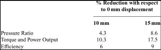
The changes in the overall turbine performance parameters with the downstream movement of the rotor are shown in Table 2.
Comparison of turbine performance parameters for different displacement configurations

The considerable reduction in torque and power output for the same flow conditions at the inlet and outlet is because of the lower expansion ratios in the higher displacement cases. If each of the displacement cases are run to the same expansion ratio by reducing the downstream vane outlet static pressure, the reduction in the torque and power are 5.8% for the 10-mm displacement case, and 11.2% for the 15-mm displacement case.
Furthermore, another set of analyses is carried out to calculate the change in turbine performance if the flow through the rim seal does not change from its value when the displacement is 0 mm. In this case it is observed that the reduction in torque and power are 9.2% for the 10-mm displacement case, and 16% for the 15-mm displacement case. This indicates that the deterioration of turbine stage performance, because of the axial displacement, is much more significant than the deterioration because of the flow from the rim seals.
4.0 CONCLUSIONS
In the present work, the turbine stage aerodynamic performance with leakage flows from the rim seal and the tip seal is compared with that of the clean configuration. The change in turbine rotor geometry, due to the downstream movement of the rotor sub-assembly during an overspeed event, is obtained from a structural LS-DYNA simulation and friction model. A secondary air system model is used to obtain the change in flow properties through the rim seals during the development of the overspeed event. Three different displacement configurations, namely 0 mm, 10 mm and 15 mm, with appropriate geometry and boundary conditions, are analysed in terms of aerodynamic performance. All the cases are examined with the same boundary conditions in the main flow inlet and downstream vane outlet. It is observed that, the 10-mm downstream displacement of the turbine rotor results in a reduction of expansion pressure ratio of 4.3%, torque and power produced of 10%, compared to the no-displacement configuration. Similarly, for the 15-mm downstream displacement case, the expansion ratio reduces by 8.5%, torque and power by 17.5%, compared to the no-displacement configuration. If in all the displacement cases, the turbines are made to run at the same pressure ratio, by changing the outlet static pressure at the downstream vane outlet, the reduction in torque and power is 5.8% for the 10-mm displacement case, and 11.2% in the 15-mm displacement case, compared to the un-displaced case. The downstream movement of the rotor also results in an increase in HP turbine mass flow function, an increase in the pressure loss coefficient of the downstream vane, and a decrease in the mass flow function of the downstream turbine.
This article has demonstrated an integrated, multi-disciplinary methodology to quantify changes in the flow behaviour of a turbine as it moves downstream during a shaft failure event. These can be further introduced into an engine thermodynamic model to predict more accurately the terminal speed of an overspeeding rotor.
ACKNOWLEDGEMENTS
The authors would like to express their gratitude to Rolls-Royce plc. for supporting this research and for permission to publish the article.