





1 Introduction
The inviscid Taylor–Culick profile has long been viewed as a suitable approximation for the internal flow field in solid rocket motors (SRMs). In practice, it stands at the foundation of a variety of phenomenological problems that continue to challenge propulsion and aeroacoustic engineers. In relation to acoustic instability prediction and mitigation, successive efforts by Griffond, Casalis & Pineau (Reference Griffond, Casalis and Pineau2000), Majdalani, Flandro & Roh (Reference Majdalani, Flandro and Roh2000), Chedevergne, Casalis & Féraille (Reference Chedevergne, Casalis and Féraille2006), Abu-Irshaid, Majdalani & Casalis (Reference Abu-Irshaid, Majdalani and Casalis2007) and Chedevergne, Casalis & Majdalani (Reference Chedevergne, Casalis and Majdalani2012) have shown that the Taylor–Culick model is capable of providing an adequate mean flow velocity to which small-amplitude oscillations may be superimposed (Majdalani Reference Majdalani2001a ; Majdalani & Flandro Reference Majdalani and Flandro2002). In modelling the effects of metallized particle loading and particle–mean flow interactions, this particular motion has fallen at the epicentre of hydrodynamic stability investigations, as evidenced in the works of Beddini & Roberts (Reference Beddini and Roberts1988), Ugurtas et al. (Reference Ugurtas, Avalon, Lupoglazoff, Vuillot and Casalis2000), Griffond & Casalis (Reference Griffond and Casalis2001), Féraille, Casalis & Dupays (Reference Féraille, Casalis and Dupays2002), Griffond (Reference Griffond2002), Fabignon et al. (Reference Fabignon, Dupays, Avalon, Vuillot, Lupoglazoff, Casalis and Prévost2003) and Féraille & Casalis (Reference Féraille and Casalis2003). The latter, for instance, has been effective at elucidating the strong connection between surface receptivity and acoustic resonance in idealized rocket chambers with sidewall injection. Along similar lines, the use of the Taylor–Culick profile to estimate bulk kinematic speeds and particle accelerations has become commonplace, especially in large-scale Navier–Stokes solvers that entail both fluid and particle–structure interactions. One may refer in this regard to the work of Balachandar, Buckmaster & Short (Reference Balachandar, Buckmaster and Short2001), Jackson, Najjar & Buckmaster (Reference Jackson, Najjar and Buckmaster2005), Najjar et al. (Reference Najjar, Ferry, Haselbacher and Balachandar2006), Haselbacher et al. (Reference Haselbacher, Najjar, Massa and Moser2010), as well as others. In reactive flow simulations, the Taylor–Culick model has proven to be so valuable in mimicking the bulk gaseous motion that it has been either programmed directly into simulation codes or judiciously employed as a limiting process verification tool. Few relevant investigations may be cited in this regard, and these include Chu, Yang and Majdalani’s premixed propane–air simulations of internally burning solid propellants (Chu, Yang & Majdalani Reference Chu, Yang and Majdalani2003), Venugopal, Moser and Najjar’s compressible Navier–Stokes computations of the injection-driven motion in SRMs with homogeneous grains (Venugopal, Moser & Najjar Reference Venugopal, Moser and Najjar2008) and Chedevergne, Casalis and Majdalani’s direct numerical simulations of both mean and unsteady flow structures evolving in SRMs (Chedevergne et al. Reference Chedevergne, Casalis and Majdalani2012).
The traditional Taylor–Culick (TC) model may be categorized as being steady, rotational, axisymmetric, inviscid and incompressible (Culick Reference Culick1966). Simply stated, it represents an exact solution of Euler’s equations, which is driven by pressure forces in a frictionless environment, where a carefully posed wall-normal injection requirement leads to a vanishing axial velocity at the porous sidewall. Furthermore, recognizing that the TC velocity and vorticity fields remain strictly orthogonal, the corresponding solution may be classified as being complex lamellar (Majdalani Reference Majdalani2012). By way of improvement, it has been modified by Majdalani, Vyas & Flandro (Reference Majdalani, Vyas and Flandro2002, Reference Majdalani, Vyas and Flandro2009), Majdalani & Akiki (Reference Majdalani and Akiki2010) and Xu et al. (Reference Xu, Lin, Liao, Wu and Majdalani2010) to account for viscous shear and regressing wall boundaries, by Kurdyumov (Reference Kurdyumov2006) to predict the deviations caused by non-circular cross-sections, by Majdalani (Reference Majdalani2007b ) and Maicke & Majdalani (Reference Maicke and Majdalani2008) to assimilate the effects of fluid dilatation, by Majdalani & Saad (Reference Majdalani and Saad2007) to permit the imposition of variable headwall injection and by Bouyges, Chedevergne & Casalis (Reference Bouyges, Chedevergne and Casalis2016) to capture the flow deviations associated with star-shaped grains. Granted that sidewall injection constitutes the primary driver in this idealized rocket chamber, the modified TC approximation has been tuned into a suitable model for hybrid rocket flow fields through the imposition of high-speed injection at the forward end (Majdalani Reference Majdalani2007a ). An integral formulation of this problem under compressible flow conditions has also been advanced by a variety of research groups in the context of elongated porous chambers with both uniform and non-uniform wall fluxes (Traineau, Hervat & Kuentzmann Reference Traineau, Hervat and Kuentzmann1986; Balakrishnan, Liñan & Williams Reference Balakrishnan, Liñan and Williams1992; Akiki & Majdalani Reference Akiki and Majdalani2012, Reference Akiki and Majdalani2016).
Clearly, the TC profile stands as one of the most frequently cited cold flow approximations for cylindrically shaped rocket motors (Kuentzmann Reference Kuentzmann1991). This is especially true in applications that benefit from the use of closed-form mean flow representations (Yamada, Goto & Ishikawa Reference Yamada, Goto and Ishikawa1976; Dunlap et al. Reference Dunlap, Blackner, Waugh, Brown and Willoughby1990; Casalis, Avalon & Pineau Reference Casalis, Avalon and Pineau1998; Avalon & Josset Reference Avalon and Josset2006). Among relevant applications, one may bring into perspective those concerned with combustion instability (Flandro & Majdalani Reference Flandro and Majdalani2003; Majdalani, Fischbach & Flandro Reference Majdalani, Fischbach and Flandro2006; Flandro, Fischbach & Majdalani Reference Flandro, Fischbach and Majdalani2007) and vortico-acoustic wave propagation (Majdalani & Roh Reference Majdalani and Roh2000, Reference Majdalani and Roh2001; Majdalani Reference Majdalani2001b , Reference Majdalani2009), as well as those devoted to hydrodynamic stability analyses in porous chambers both with and without particle interactions (Féraille & Casalis Reference Féraille and Casalis2003; Chedevergne et al. Reference Chedevergne, Casalis and Féraille2006; Abu-Irshaid et al. Reference Abu-Irshaid, Majdalani and Casalis2007; Chedevergne et al. Reference Chedevergne, Casalis and Majdalani2012). Using variational calculus, the Lagrangian optimization principle is further extended to this problem where two types of continual spectra of quantum-like energy states of the TC solution are identified, and these have been essentially shown to evolve from a purely irrotational Hart–McClure mean flow motion (with least kinetic energy) to a fully rotational profile requiring the most energy to excite (Saad & Majdalani Reference Saad and Majdalani2010). In all cases considered, simple sinusoidal approximations are obtained assuming sufficiently long chambers. These solutions are subsequently verified and discussed in light of Kelvin’s minimum energy theorem as well as the entropy maximization principle.
In the spirit of verification, a collective body of research seems to have examined the TC shape and spatial development in a series of dedicated investigations. These start with the classical laboratory measurements acquired by Taylor (Reference Taylor1956) and evolve through a plethora of computational (Dunlap, Willoughby & Hermsen Reference Dunlap, Willoughby and Hermsen1974; Baum, Levine & Lovine Reference Baum, Levine and Lovine1988; Sabnis, Gibeling & McDonald Reference Sabnis, Gibeling and McDonald1989; Apte & Yang Reference Apte and Yang2000), experimental (Yamada et al. Reference Yamada, Goto and Ishikawa1976; Dunlap et al. Reference Dunlap, Blackner, Waugh, Brown and Willoughby1990; Casalis et al. Reference Casalis, Avalon and Pineau1998; Avalon & Josset Reference Avalon and Josset2006) and theoretical studies (Clayton Reference Clayton1996; Barron, Van Moorhem & Majdalani Reference Barron, Van Moorhem and Majdalani2000; Majdalani & Roh Reference Majdalani and Roh2000; Majdalani & Van Moorhem Reference Majdalani and Van Moorhem2001; Zhou & Majdalani Reference Zhou and Majdalani2002) for both cylindrically shaped and planar rocket configurations. Most of these endeavours tend to confirm the suitability of the TC model in approximating the bulk flow in a simulated SRM (Kuentzmann Reference Kuentzmann1991), although many seem to recognize the natural tendency of the flow to develop a non-zero swirl component, and, hence, axial vorticity, in a sufficiently long chamber with circular cross-section (Dunlap et al. Reference Dunlap, Blackner, Waugh, Brown and Willoughby1990; Balachandar et al. Reference Balachandar, Buckmaster and Short2001; Najjar et al. Reference Najjar, Ferry, Haselbacher and Balachandar2006). The reader may be referred in this regard to the classic cold flow simulations of SRMs by Dunlap et al. (Reference Dunlap, Blackner, Waugh, Brown and Willoughby1990), which for many years have provided the propulsion community with invaluable measurements of mean and oscillatory flow fields in cylindrical cavities with transpiring walls. Accordingly, the experimentally observed mean flow is shown to exhibit a tangential component of motion, as depicted in figure 1 (Dunlap et al. Reference Dunlap, Willoughby and Hermsen1974).
Besides its relevance in propulsion, the TC solution has proven to be surprisingly accurate in modelling the drainage mechanism associated with watery suspensions through porous sheets. It has also been effectively employed in the treatment of surface ablation and sweat cooling (Yuan Reference Yuan1959; Peng & Yuan Reference Peng and Yuan1965).
Schematic of a swirling rocket flow according to the dedicated laboratory experiments by Dunlap et al. (Reference Dunlap, Willoughby and Hermsen1974). Here
 $r$
and
 $z$
denote the radial and axial coordinates, respectively, and the overbar denotes a dimensional quantity.

Among the theoretical studies that address the TC problem, and that specifically explain the tendency of the TC profile to develop axial vorticity, one of the most relevant to the present work consists of a dedicated article by Balachandar et al. (Reference Balachandar, Buckmaster and Short2001). The latter may be perceived as one of the earliest to address the natural evolution of swirl within the core of a simulated SRM, thus helping to explain the existence of swirl in Dunlap’s experiments. Accordingly, by modelling the motor as a cylindrical tube that is driven by sidewall mass addition, swirl is introduced either as a small perturbation to the radial injection velocity or as a small fluctuation in the radial location of the wall injection condition. To overcome the attendant singularity that occurs at the centreline, which is manifested in the form of an unbounded tangential velocity at
 $r\rightarrow 0$
, the governing equations are regularized by accounting for small viscous effects. Subsequently, a small viscous patch, which may be constructed asymptotically, is developed near the centreline.
In this study, we discuss how the TC mean flow may be identically recovered from a partial solution of the Bragg–Hawthorne equation (BHE). The latter represents a reduced form of Euler’s equation, which arises in the context of steady, inviscid and generally axisymmetric motions. We also show that its physicality may be intimately connected to its character being of the complex-lamellar type. We also show that the same BHE may be used to extract another partial solution under somewhat similar conditions, namely conditions that involve a swirling flow field. This new solution proves to be of the Trkalian type, thus exhibiting velocities and vorticities that are globally parallel. In comparison to the original TC streamfunction, which is sinusoidal in nature, the new model leads to a Bessel function representation that will be systematically examined and discussed.
2 Formulation
2.1 Geometric configuration
As schematically illustrated in figure 2, a typical SRM may be idealized as a right-cylindrical enclosure of porous length
 $L_{0}$
and radius
 $a$
, with either a reactive or a non-reactive headwall, and a nozzleless aft closure. The radial, tangential and axial velocities may be represented by
 $(\bar{u}_{r},\bar{u}_{\unicode[STIX]{x1D703}},\bar{u}_{z})$
, where overbars denote dimensional quantities and
 $\bar{\boldsymbol{u}}$
represents the velocity vector. The corresponding spatial coordinates are given by
 $(\bar{r},\unicode[STIX]{x1D703},\bar{z})$
, where
 $0\leqslant \bar{r}\leqslant a$
,
 $0\leqslant \unicode[STIX]{x1D703}\leqslant 2\unicode[STIX]{x03C0}$
and
 $0\leqslant \bar{z}\leqslant L_{0}$
define the range over which the solution may be extended, specifically from the headwall to the typical nozzle attachment point in the chamber exit plane. As usual, the dependence on
 $\unicode[STIX]{x1D703}$
may be relaxed by virtue of axisymmetry. As shown in figure 2, secondary fluid injection may be superimposed at the headwall, where an oxidizer or gaseous propellant stream may be allowed to enter axially at a user-defined velocity
 $\bar{u}_{0}(\bar{r})$
. This could be prescribed by
 $$\begin{eqnarray}\bar{u}_{0}(\bar{r})=\bar{u}_{z}(\bar{r},0)=\left\{\begin{array}{@{}ll@{}}U_{c}\cos \left({\textstyle \frac{1}{2}}\unicode[STIX]{x03C0}\bar{r}^{2}/a^{2}\right)\!,\quad & \text{Berman's half cosine}~{-}~\text{complex}\text{-}\text{lamellar flow},\\ U_{c}J_{0}(j_{0,1}\bar{r}/a),\quad & \text{Bessel function}~{-}~\text{Beltramian flow},\end{array}\right.\end{eqnarray}$$
where
 $j_{0,1}$
refers to the first root of the zeroth-order Bessel function of the first kind. In the above,
 $U_{c}=\bar{u}_{z}(0,0)$
stands for the centreline speed at the headwall, which may be set equal to zero in the case of a non-reactive and non-injecting headwall. Otherwise, the axial stream entering at
 $z=0$
may be permitted to merge with the laterally incoming crossflow originating at the sidewall. Practically, one may correlate
 $\bar{u}_{r}(a,\bar{z})=-U_{w}$
to the grain regression rate and, although
 $U_{w}$
will be considerably smaller than
 $U_{c}$
in hybrid rocket analysis (due to the slowly evolving pyrolysis of inert fuels), these two parameters will be of the same order of magnitude in simulated SRMs.
Schematics of a right-cylindrical internal burning rocket with an axisymmetric headwall injection function.

2.2 Equations and boundary conditions
We begin with Euler’s steady and incompressible equations, which consist of continuity,
 $\bar{\unicode[STIX]{x1D735}}\boldsymbol{\cdot }\bar{\boldsymbol{u}}=0$
, and the steady-state momentum expression,
 $\bar{\unicode[STIX]{x1D735}}\bar{p}/\bar{\unicode[STIX]{x1D70C}}=\bar{\boldsymbol{u}}\times \bar{\unicode[STIX]{x1D734}}-\bar{\unicode[STIX]{x1D735}}(\bar{\boldsymbol{u}}\boldsymbol{\cdot }\bar{\boldsymbol{u}})/2$
, where
 $\bar{p}$
,
 $\bar{\unicode[STIX]{x1D70C}}$
and
 $\bar{\unicode[STIX]{x1D734}}$
denote the mean pressure, density and vorticity. Our explicitly imposed conditions are simply due to axisymmetry and wall-normal injection at both the headwall and sidewall boundaries. Consistently with the original TC model, we also prohibit swirl at the headwall centre in the case of a non-injecting headwall. These conditions translate into:
-
(i) a vanishing radial velocity along the axis of symmetry,
 $\bar{u}_{r}(0,\bar{z})=0$
;
-
(ii) a vanishing axial velocity at the sidewall,
$\bar{u}_{z}(a,\bar{z})=0$
; -
(iii) a uniform injection at the sidewall,
$\bar{u}_{r}(a,\bar{z})=-U_{w}$
; -
(iv) a prescribed injection pattern at the headwall,
$\bar{u}_{z}(\bar{r},0)=\bar{u}_{0}(\bar{r})$
; and -
(v) a vanishing swirl velocity at the headwall centre,
$\bar{u}_{\unicode[STIX]{x1D703}}(0,0)=0$
.


This last condition is often overlooked, although it is essential to the proper derivation of the TC profile, where it is implicitly applied.
2.3 Normalization
Using the radius
 $a$
and the sidewall injection speed
 $U_{w}$
as reference values, all recurring flow variables and operators may be re-established as
 $$\begin{eqnarray}\left.\begin{array}{@{}c@{}}r={\displaystyle \frac{\bar{r}}{a}},\quad z={\displaystyle \frac{\bar{z}}{a}},\quad u_{r}={\displaystyle \frac{\bar{u}_{r}}{U_{w}}},\quad u_{\unicode[STIX]{x1D703}}={\displaystyle \frac{\bar{u}_{\unicode[STIX]{x1D703}}}{U_{w}}},\quad u_{z}={\displaystyle \frac{\bar{u}_{z}}{U_{w}}},\quad p={\displaystyle \frac{\bar{p}}{\bar{\unicode[STIX]{x1D70C}}U_{w}^{2}}},\\ \unicode[STIX]{x1D734}={\displaystyle \frac{\bar{\unicode[STIX]{x1D734}}a}{U_{w}}},\quad \unicode[STIX]{x1D713}={\displaystyle \frac{\bar{\unicode[STIX]{x1D713}}}{a^{2}U_{w}}},\quad \unicode[STIX]{x1D735}=a\bar{\unicode[STIX]{x1D735}},\quad L={\displaystyle \frac{L_{0}}{a}},\quad u_{0}={\displaystyle \frac{\bar{u}_{0}}{U_{w}}},\quad u_{c}={\displaystyle \frac{U_{c}}{U_{w}}},\end{array}\right\}\end{eqnarray}$$
where
 $\bar{\unicode[STIX]{x1D713}}$
stands for the streamfunction. As we consider the basic motion to be inviscid, rotational, incompressible, axisymmetric and steady, Euler’s normalized momentum equation may be reduced to
 $\unicode[STIX]{x1D735}p=\boldsymbol{u}\times \unicode[STIX]{x1D734}-\unicode[STIX]{x1D735}(\boldsymbol{u}\boldsymbol{\cdot }\boldsymbol{u})/2$
. The pressure may be conveniently eliminated by curling Euler’s equation, thus transforming it into the steady-state vorticity transport equation (VTE),
 $\unicode[STIX]{x1D735}\times (\boldsymbol{u}\times \unicode[STIX]{x1D734})=0.$
Additionally, continuity,
 $\unicode[STIX]{x1D735}\boldsymbol{\cdot }\boldsymbol{u}=0$
, may be secured through the use of the Stokes streamfunction, namely
 $$\begin{eqnarray}u_{r}=-\frac{1}{r}\frac{\unicode[STIX]{x2202}\unicode[STIX]{x1D713}}{\unicode[STIX]{x2202}z}\quad \text{and}\quad u_{z}=\frac{1}{r}\frac{\unicode[STIX]{x2202}\unicode[STIX]{x1D713}}{\unicode[STIX]{x2202}r}.\end{eqnarray}$$
Forthwith, the auxiliary conditions of the problem become
 $$\begin{eqnarray}\displaystyle & \displaystyle u_{r}(0,z)=\lim _{r\rightarrow 0}{\displaystyle \frac{1}{r}}{\displaystyle \frac{\unicode[STIX]{x2202}\unicode[STIX]{x1D713}(r,z)}{\unicode[STIX]{x2202}z}}=0, & \displaystyle\end{eqnarray}$$
 $$\begin{eqnarray}\displaystyle & \displaystyle u_{z}(1,z)={\displaystyle \frac{\unicode[STIX]{x2202}\unicode[STIX]{x1D713}(1,z)}{\unicode[STIX]{x2202}r}}=0, & \displaystyle\end{eqnarray}$$
 $$\begin{eqnarray}\displaystyle & \displaystyle u_{r}(1,z)=-{\displaystyle \frac{\unicode[STIX]{x2202}\unicode[STIX]{x1D713}(1,z)}{\unicode[STIX]{x2202}z}}=-1, & \displaystyle\end{eqnarray}$$
 $$\begin{eqnarray}\displaystyle & \displaystyle u_{z}(r,0)={\displaystyle \frac{1}{r}}{\displaystyle \frac{\unicode[STIX]{x2202}\unicode[STIX]{x1D713}(r,0)}{\unicode[STIX]{x2202}r}}=u_{0}, & \displaystyle\end{eqnarray}$$
 $$\begin{eqnarray}\displaystyle & \displaystyle u_{\unicode[STIX]{x1D703}}(0,0)=0, & \displaystyle\end{eqnarray}$$
 $$\begin{eqnarray}\displaystyle & \displaystyle u_{0}(r)=\left\{\begin{array}{@{}ll@{}}0,\quad & \text{inert},\\ u_{c}\cos \left({\textstyle \frac{1}{2}}\unicode[STIX]{x03C0}r^{2}\right),\quad u_{c}=\unicode[STIX]{x03C0}u_{h},\quad & \text{Berman},\\ u_{c}J_{0}(j_{0,1}r),\quad u_{c}={\displaystyle \frac{u_{h}j_{0,1}}{J_{1}(j_{0,1})}},\quad & \text{Bessel}.\end{array}\right. & \displaystyle\end{eqnarray}$$
 $r=0$
may be manipulated using L’Hôpital’s rule to produce two equivalent but finite constraints,
 $$\begin{eqnarray}\frac{\unicode[STIX]{x2202}\unicode[STIX]{x1D713}(0,z)}{\unicode[STIX]{x2202}z}=0\quad \text{and}\quad \frac{\unicode[STIX]{x2202}^{2}\unicode[STIX]{x1D713}(0,z)}{\unicode[STIX]{x2202}r\unicode[STIX]{x2202}z}=0.\end{eqnarray}$$
2.4 Traditional TC technique
The traditional vorticity–streamfunction technique used by Culick (Reference Culick1966) proceeds by eliminating the pressure and velocities in favour of the vorticity and streamfunction. After determining a generic relationship between the vorticity and the streamfunction, which can satisfy the VTE identically, substitution into the vorticity equation leads to a second-order partial differential equation that can be solved for
 $\unicode[STIX]{x1D713}$
. As further confirmed in the analogous treatment of the problem with viscosity and headwall injection (Majdalani & Akiki Reference Majdalani and Akiki2010), the VTE may be fulfilled by taking
 $\unicode[STIX]{x1D734}_{\unicode[STIX]{x1D703}}=r\unicode[STIX]{x1D6EF}(\unicode[STIX]{x1D713})$
. To ensure linearity of the ensuing vorticity equation, Culick (Reference Culick1966) then inserts
 $\unicode[STIX]{x1D6EF}={\mathcal{C}}^{2}\unicode[STIX]{x1D713}$
into the vorticity equation,
 $\unicode[STIX]{x1D734}=\unicode[STIX]{x1D735}\times \boldsymbol{u}$
(which may be written in terms of
 $\unicode[STIX]{x1D713}$
only), to the extent of arriving at
 $$\begin{eqnarray}\frac{\unicode[STIX]{x2202}^{2}\unicode[STIX]{x1D713}}{\unicode[STIX]{x2202}z^{2}}+\frac{\unicode[STIX]{x2202}^{2}\unicode[STIX]{x1D713}}{\unicode[STIX]{x2202}r^{2}}-\frac{1}{r}\frac{\unicode[STIX]{x2202}\unicode[STIX]{x1D713}}{\unicode[STIX]{x2202}r}+{\mathcal{C}}^{2}r^{2}\unicode[STIX]{x1D713}=0.\end{eqnarray}$$
As usual, separation of variables may be employed in concert with a zero separation constant to produce
 $\unicode[STIX]{x1D713}=(c_{1}z+c_{2})[c_{3}\sin ({\mathcal{C}}r^{2})/2+c_{4}\cos ({\mathcal{C}}r^{2})/2]$
. The remaining constants may be deduced using a straightforward application of (2.4). In the process, (2.5a
) may be used to replace the limiting constraint in (2.4). As such, (2.5b
) becomes self-satisfying. Finally, assuming a similarity-conforming injection pattern at the headwall, i.e.
 $u_{0}(r)=u_{c}\cos (\unicode[STIX]{x03C0}r^{2})/2$
, the extended TC profile emerges in the form of
 $\unicode[STIX]{x1D713}=(z+u_{h})\sin (\unicode[STIX]{x03C0}r^{2})/2$
, with
 $u_{h}\equiv u_{c}/\unicode[STIX]{x03C0},$
and
 $$\begin{eqnarray}\unicode[STIX]{x1D734}=\unicode[STIX]{x03C0}^{2}(z+u_{h})r\sin \left({\textstyle \frac{1}{2}}\unicode[STIX]{x03C0}r^{2}\right)\boldsymbol{e}_{\unicode[STIX]{x1D703}},\quad \boldsymbol{u}=-r^{-1}\sin \left({\textstyle \frac{1}{2}}\unicode[STIX]{x03C0}r^{2}\right)\boldsymbol{e}_{r}+\unicode[STIX]{x03C0}(z+u_{h})\cos \left({\textstyle \frac{1}{2}}\unicode[STIX]{x03C0}r^{2}\right)\boldsymbol{e}_{z}.\end{eqnarray}$$
It should be noted that (2.4), which precludes the presence of swirl, is implicitly used, thus leading to a vanishing tangential velocity component. In what follows, it will be shown that the above formulation is retrievable directly from the BHE, where the relevance of the no-swirl requirement will be illuminated.
2.5 Bragg–Hawthorne technique
The BHE consists of a reduced scalar equivalent of Euler’s equation, which is specifically realized under the auspices of flow steadiness and axisymmetry. Also known as the Squire-Long equation, the BHE is defined by Batchelor (Reference Batchelor1967) as a partial differential equation linking the streamfunction
 $\bar{\unicode[STIX]{x1D713}}$
to the angular momentum
 $\bar{B}=\bar{r}\bar{u}_{\unicode[STIX]{x1D703}}$
and the total fluid head
 $\bar{H}=\bar{p}/\bar{\unicode[STIX]{x1D70C}}+\bar{\boldsymbol{u}}\boldsymbol{\cdot }\bar{\boldsymbol{u}}/2$
. Dimensionally, it may be given by
 $$\begin{eqnarray}\frac{\unicode[STIX]{x2202}^{2}\bar{\unicode[STIX]{x1D713}}}{\unicode[STIX]{x2202}\bar{r}^{2}}-\frac{1}{\bar{r}}\frac{\unicode[STIX]{x2202}\bar{\unicode[STIX]{x1D713}}}{\unicode[STIX]{x2202}\bar{r}}+\frac{\unicode[STIX]{x2202}^{2}\bar{\unicode[STIX]{x1D713}}}{\unicode[STIX]{x2202}\bar{z}^{2}}=\bar{r}^{2}\frac{\text{d}\bar{H}}{\text{d}\bar{\unicode[STIX]{x1D713}}}-\bar{B}\frac{\text{d}\bar{B}}{\text{d}\bar{\unicode[STIX]{x1D713}}},\end{eqnarray}$$
and so, using
 $B=\bar{B}/(aU_{w})$
and
 $H=\bar{H}/U_{w}^{2},$
the non-dimensional BHE emerges as
 $$\begin{eqnarray}\frac{\unicode[STIX]{x2202}^{2}\unicode[STIX]{x1D713}}{\unicode[STIX]{x2202}r^{2}}-\frac{1}{r}\frac{\unicode[STIX]{x2202}\unicode[STIX]{x1D713}}{\unicode[STIX]{x2202}r}+\frac{\unicode[STIX]{x2202}^{2}\unicode[STIX]{x1D713}}{\unicode[STIX]{x2202}z^{2}}=r^{2}\frac{\text{d}H}{\text{d}\unicode[STIX]{x1D713}}-B\frac{\text{d}B}{\text{d}\unicode[STIX]{x1D713}},\end{eqnarray}$$
where
 $B=ru_{\unicode[STIX]{x1D703}}$
and
 $H=p+\boldsymbol{u}\boldsymbol{\cdot }\boldsymbol{u}/2$
. In some respects, (2.9) embraces the vorticity–streamfunction framework by incorporating its essential components into a form that may be straightforwardly tackled to achieve a solution. For example, (2.6) used by Culick (Reference Culick1966) may be directly recovered from (2.9) by implicitly assuming a constant angular momentum and a total head that varies with
 $\unicode[STIX]{x1D713}^{2}$
. Such conditions lead to
 $$\begin{eqnarray}B\frac{\text{d}B}{\text{d}\unicode[STIX]{x1D713}}=0\quad B(\unicode[STIX]{x1D713})=B_{0}=\text{const.}\quad \text{or}\quad u_{\unicode[STIX]{x1D703}}=\frac{B_{0}}{r},\end{eqnarray}$$
where
 $B_{0}=0$
may be imposed to mitigate the development of axial swirl. Since the requirement for a constant stagnation head along streamlines stems from the association of the BHE with steady, inviscid and adiabatic motion, the second constraint enables us to specify a quadratic relation between the stagnation head and the streamfunction that leads to an invariant stagnation head along streamlines while linearizing the right-hand side of the BHE. This is accomplished by taking
 $$\begin{eqnarray}\frac{\text{d}H}{\text{d}\unicode[STIX]{x1D713}}=-{\mathcal{C}}^{2}\unicode[STIX]{x1D713}\quad \text{or}\quad H(\unicode[STIX]{x1D713})=-{\textstyle \frac{1}{2}}{\mathcal{C}}^{2}\unicode[STIX]{x1D713}^{2}+H_{0},\end{eqnarray}$$
where
 $H_{0}$
is a constant. These expressions enable us to reduce the BHE into (2.6), whence the classical TC solution may be readily returned. Along similar lines, it may be instructive to note that the cyclonic model used to describe the bidirectional vortex motion engendered in a right-cylindrical chamber may be equivalently restored from (2.9) under the same assumptions and a non-vanishing
 $B_{0}=1$
. The resulting profile may be traced back to Vyas & Majdalani (Reference Vyas and Majdalani2006), who produced a strikingly similar solution to the TC flow velocity, namely
 $$\begin{eqnarray}\left.\begin{array}{@{}c@{}}\unicode[STIX]{x1D713}=\unicode[STIX]{x1D705}z\sin (\unicode[STIX]{x03C0}r^{2}),\quad \unicode[STIX]{x1D734}=4\unicode[STIX]{x03C0}^{2}rz\sin (\unicode[STIX]{x03C0}r^{2})\boldsymbol{e}_{\unicode[STIX]{x1D703}},\\ \boldsymbol{u}=-\unicode[STIX]{x1D705}r^{-1}\sin (\unicode[STIX]{x03C0}r^{2})\boldsymbol{e}_{r}+r^{-1}\boldsymbol{e}_{\unicode[STIX]{x1D703}}+2\unicode[STIX]{x03C0}\unicode[STIX]{x1D705}z\cos (\unicode[STIX]{x03C0}r^{2})\boldsymbol{e}_{z}.\end{array}\right\}\end{eqnarray}$$
In comparison to the TC solution, which remains swirl and parameter free, (2.12) comprises a non-zero swirl component and an off-swirl Ekman number,
 $\unicode[STIX]{x1D705}=a/(2\unicode[STIX]{x03C0}\unicode[STIX]{x1D70E}L_{0})$
, where
 $\unicode[STIX]{x1D70E}$
stands for the swirl number.
3 Exact Trkalian mean flow
3.1 Bragg–Hawthorne representation
In seeking a possible alternative to the TC mean flow for a swirling flow field, the versatility of the BHE framework may be favourably tested. In fact, a viable set of assumptions that are frequently used in the modelling of helical flows includes a globally constant stagnation head, i.e.
 $$\begin{eqnarray}\frac{\text{d}H}{\text{d}\unicode[STIX]{x1D713}}=0\quad \text{or}\quad H(\unicode[STIX]{x1D713})=H_{0}=\text{const.}\end{eqnarray}$$
To justify the use of a constant stagnation head, the flow is assumed to be homenergic. The simplifying stagnation head expression may then be implemented in conjunction with an angular momentum rate that obeys
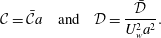
 $$\begin{eqnarray}B\frac{\text{d}B}{\text{d}\unicode[STIX]{x1D713}}={\mathcal{C}}^{2}\unicode[STIX]{x1D713},\quad B^{2}={\mathcal{C}}^{2}\unicode[STIX]{x1D713}^{2}+{\mathcal{D}}\quad \text{or}\quad u_{\unicode[STIX]{x1D703}}=\frac{\sqrt{{\mathcal{C}}^{2}\unicode[STIX]{x1D713}^{2}+{\mathcal{D}}}}{r},\end{eqnarray}$$
where the non-dimensional forms of
 ${\mathcal{C}}$
and
 ${\mathcal{D}}$
correspond to
 $$\begin{eqnarray}{\mathcal{C}}=\bar{{\mathcal{C}}}a\quad \text{and}\quad {\mathcal{D}}=\frac{\bar{{\mathcal{D}}}}{U_{w}^{2}a^{2}}.\end{eqnarray}$$
In the foregoing,
 ${\mathcal{C}}$
and
 ${\mathcal{D}}$
may be defined as the rotational momentum and headwall parameters, respectively. Since
 ${\mathcal{C}}$
provides the connection between the tangential velocity and the streamfunction to secure a rotational flow field, it may be specified in such a manner as to produce
 $u_{z}(1,z)=0$
by suppressing the axial velocity at the sidewall; this requirement will be fulfilled through (3.8) below. As for
 ${\mathcal{D}}$
, it will be later specified by the boundary condition imposed on
 $u_{\unicode[STIX]{x1D703}}$
, namely through
 $u_{\unicode[STIX]{x1D703}}(0,0)=0$
, which compels the tangential velocity to vanish at the headwall centre. Finally, in compliance with (3.1) and (3.2), (2.9) collapses into
 $$\begin{eqnarray}\frac{\unicode[STIX]{x2202}^{2}\unicode[STIX]{x1D713}}{\unicode[STIX]{x2202}r^{2}}-\frac{1}{r}\frac{\unicode[STIX]{x2202}\unicode[STIX]{x1D713}}{\unicode[STIX]{x2202}r}+\frac{\unicode[STIX]{x2202}^{2}\unicode[STIX]{x1D713}}{\unicode[STIX]{x2202}z^{2}}+{\mathcal{C}}^{2}\unicode[STIX]{x1D713}=0.\end{eqnarray}$$
3.2 General and partial solutions
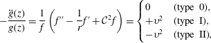
Guided by the linearity of (3.4), a product solution of the form
 $\unicode[STIX]{x1D713}(r,z)=f(r)g(z)$
may be attempted. We obtain
 $$\begin{eqnarray}-\frac{\ddot{g}(z)}{g(z)}=\frac{1}{f}\left(f^{\prime \prime }-\frac{1}{r}f^{\prime }+{\mathcal{C}}^{2}f\right)=\left\{\begin{array}{@{}ll@{}}0\quad & \text{(type 0)},\\ +\unicode[STIX]{x1D710}^{2}\quad & \text{(type I)},\\ -\unicode[STIX]{x1D710}^{2}\quad & \text{(type II)},\end{array}\right.\end{eqnarray}$$
where
 $\unicode[STIX]{x1D710}$
is the separation constant. For each of the three possible separation outcomes, we get
 $$\begin{eqnarray}\displaystyle & & \displaystyle \unicode[STIX]{x1D713}(r,z)\nonumber\\ \displaystyle & & \displaystyle =\left\{\begin{array}{@{}ll@{}}r(c_{1}z+c_{2})[c_{3}J_{1}({\mathcal{C}}r)+c_{4}Y_{1}({\mathcal{C}}r)]\quad & \text{(type 0)},\\ r[c_{1}\sin (\unicode[STIX]{x1D710}z)+c_{2}\cos (\unicode[STIX]{x1D710}z)]\left[c_{3}J_{1}(r\sqrt{{\mathcal{C}}^{2}-\unicode[STIX]{x1D710}^{2}})+c_{4}Y_{1}(r\sqrt{{\mathcal{C}}^{2}-\unicode[STIX]{x1D710}^{2}})\right]\quad & \text{(type I)},\\ r[c_{1}\sinh (\unicode[STIX]{x1D710}z)+c_{2}\cosh (\unicode[STIX]{x1D710}z)]\left[c_{3}J_{1}(r\sqrt{{\mathcal{C}}^{2}+\unicode[STIX]{x1D710}^{2}})+c_{4}Y_{1}(r\sqrt{{\mathcal{C}}^{2}+\unicode[STIX]{x1D710}^{2}})\right]\quad & \text{(type II)},\end{array}\right.\nonumber\\ \displaystyle & & \displaystyle\end{eqnarray}$$
where
 $J_{1}(x)$
and
 $Y_{1}(x)$
represent the Bessel functions of the first and second kinds, respectively. In seeking a simple outcome, our main attention will be initially turned to partial solutions of type 0, as these stand to produce compact expressions that could be compared with those attributed to Culick (Reference Culick1966), Vyas & Majdalani (Reference Vyas and Majdalani2006) and Majdalani (Reference Majdalani2012). It should also be indicated that the product solution assumed here has been shown to deteriorate in the neighbourhood of the headwall, where a singularity arises due to the radial injection at the corner of the chamber, which sweeps across the headwall. Such a singularity may be treated using a judicious boundary layer analysis, as described by Chedevergne et al. (Reference Chedevergne, Casalis and Féraille2006, Reference Chedevergne, Casalis and Majdalani2012).
In all cases considered, one must set
 $c_{4}=0$
to suppress the singularity that arises at
 $r=0,$
and hence satisfy (2.4), so long as the centreline continues to belong to the fluid domain. With no loss of generality, one may proceed by taking
 $c_{3}=1$
and writing, for the type 0 motion,
 $$\begin{eqnarray}\unicode[STIX]{x1D713}(r,z)=r(c_{1}z+c_{2})J_{1}({\mathcal{C}}r).\end{eqnarray}$$
At this juncture, suppression of the axial velocity at the sidewall may be used to retrieve
 $$\begin{eqnarray}u_{z}(1,z)={\mathcal{C}}(c_{1}z+c_{2})J_{0}({\mathcal{C}})=0;\quad \forall z~\text{or}~J_{0}({\mathcal{C}})=0.\end{eqnarray}$$
The eigencondition for this problem is hence identified, with the roots being the zeros of the zeroth-order Bessel function of the first kind,
 ${\mathcal{C}}=j_{0,m}=\{2.4048,5.5201,8.6537,\ldots \}$
;
 $m\in \mathbb{N}^{\ast }$
. To make further headway, the partial solution that we seek may be associated with the first zero only, specifically
 ${\mathcal{C}}=j_{0,1}=2.4048,$
which is comparable to the corresponding TC constant of
 $\unicode[STIX]{x03C0}=3.1416.$
Higher zeros will not be considered here as they lead to recirculatory regions that do not apply to the problem at hand. For simplicity, the first eigenvalue will be referred to as
 $\unicode[STIX]{x1D706}_{1}\equiv j_{0,1}$
.
Having determined
 ${\mathcal{C}}$
, the second constraint at the sidewall may be imposed on the radial velocity via
 $$\begin{eqnarray}u_{r}(1,z)=-c_{1}J_{1}(\unicode[STIX]{x1D706}_{1})=-1;\quad \forall z~\text{or}~c_{1}=J_{1}^{-1}(\unicode[STIX]{x1D706}_{1})\approx 1.9262,\end{eqnarray}$$
which leaves us with
 $\unicode[STIX]{x1D713}=r[z+c_{2}J_{1}(\unicode[STIX]{x1D706}_{1})]J_{1}(\unicode[STIX]{x1D706}_{1}r)/J_{1}(\unicode[STIX]{x1D706}_{1})$
. In the absence of headwall injection, the fourth condition may be implemented to retrieve
 $c_{2}=0$
. More generally, if we were to assume a similarity-conforming Bessel function at the headwall, we would obtain
 $$\begin{eqnarray}u_{z}(r,0)=c_{2}\unicode[STIX]{x1D706}_{1}J_{0}(\unicode[STIX]{x1D706}_{1}r)=u_{c}J_{0}(j_{0,1}r);\quad \forall r~\text{or}~c_{2}=u_{c}/\unicode[STIX]{x1D706}_{1}=U_{c}/(\unicode[STIX]{x1D706}_{1}U_{w}).\end{eqnarray}$$
The partial solution for the streamfunction can thus be rearranged into
 $$\begin{eqnarray}\unicode[STIX]{x1D713}(r,z)=r(z+u_{h})\frac{J_{1}(\unicode[STIX]{x1D706}_{1}r)}{J_{1}(\unicode[STIX]{x1D706}_{1})},\quad u_{h}\equiv u_{c}\frac{J_{1}(\unicode[STIX]{x1D706}_{1})}{\unicode[STIX]{x1D706}_{1}}=\frac{u_{c}}{4q},\quad q\equiv \frac{\unicode[STIX]{x1D706}_{1}}{4J_{1}(\unicode[STIX]{x1D706}_{1})}\approx 1.1581,\end{eqnarray}$$
where the headwall constant is consistent with the form of the similarity-conforming axial injection speed imposed at the forward closure. The fifth and final condition, which is given by (2.4e ), prohibits the onset of swirl at the headwall centre. Its fulfilment may be secured, in concert with (3.2), to deduce
 $$\begin{eqnarray}u_{\unicode[STIX]{x1D703}}(0,0)=\lim _{r\rightarrow 0}\frac{1}{r}\sqrt{\unicode[STIX]{x1D706}_{1}^{2}\left[ru_{h}\frac{J_{1}(\unicode[STIX]{x1D706}_{1}r)}{J_{1}(\unicode[STIX]{x1D706}_{1})}\right]^{2}+{\mathcal{D}}}=0\quad \text{or}\quad {\mathcal{D}}=0,\end{eqnarray}$$
and so, for the tangential velocity, we are left with
 $$\begin{eqnarray}u_{\unicode[STIX]{x1D703}}=\unicode[STIX]{x1D706}_{1}(z+u_{h})\frac{J_{1}(\unicode[STIX]{x1D706}_{1}r)}{J_{1}(\unicode[STIX]{x1D706}_{1})}=4q(z+u_{h})J_{1}(\unicode[STIX]{x1D706}_{1}r)\approx 4.6323(z+u_{h})J_{1}(\unicode[STIX]{x1D706}_{1}r).\end{eqnarray}$$
To briefly explore the behaviour of the swirl velocity across the radius, (3.13) may be evaluated as
 $r\rightarrow 0$
using a Maclaurin series of the form
 $$\begin{eqnarray}u_{\unicode[STIX]{x1D703}}\approx (z+u_{h})\left[\frac{\unicode[STIX]{x1D706}_{1}^{2}}{2J_{1}(\unicode[STIX]{x1D706}_{1})}r-\frac{\unicode[STIX]{x1D706}_{1}^{4}}{16J_{1}(\unicode[STIX]{x1D706}_{1})}r^{3}+\cdots \right]\approx 2q\unicode[STIX]{x1D706}_{1}(z+u_{h})r+O(r^{3}).\end{eqnarray}$$
The forced vortex behaviour near the centreline, where
 $u_{\unicode[STIX]{x1D703}}\rightarrow \unicode[STIX]{x1D714}_{f}r$
, is therefore evident. The solid body rotation imposed on the gases as they approach the core axis may be estimated from
 $\unicode[STIX]{x1D714}_{f}\approx 5.5699\left(z+u_{h}\right)$
, which represents a linearly increasing forced angular frequency. Furthermore, as shown in figure 3, the forced vortex behaviour – where the tangential speed remains linearly proportional to the radial distance from the axis of rotation – extends over a considerable portion of the chamber. Subsequently, the speed reaches a maximum value of
 $2.6954(z+u_{h})$
at a radius of
 $r=r_{max}\approx 0.7656$
and then diminishes to a value of
 $\unicode[STIX]{x1D706}_{1}(z+u_{h})\approx 2.4048(z+u_{h})$
at the sidewall. In what follows, the various properties of the flow will be considered one-by-one and discussed.
Vector plot of (a) the Trkalian swirl velocity relative to (b) a similarly inviscid free vortex, such as the type that could have accompanied the TC profile. Comparisons are drawn at
 $z=1.$

3.3 Flow properties
To better describe the motion associated with the present solution relative to its non-swirling TC counterpart, two representative streaklines from each model are depicted in figure 4. Therein, two orthogonal views of a simulated rocket motor are featured using the two inviscid solutions at hand. In figure 4(a), using a top view of the motor, we are able to confirm the inability of the helical streakline to enter the chamber at a right angle, due to its finite swirl component at the wall. As for figure 4(b), the spiralling paths followed by the two streaklines seem to be consistent, albeit qualitatively only, with the flow depiction provided by Dunlap et al. (Reference Dunlap, Willoughby and Hermsen1974) and reproduced here as figure 1. In contrast, the TC streaklines displayed in figure 4(c,d) remain swirl-free. Nonetheless, the TC axial and radial velocities remain a better match with Dunlap’s experimental measurements, which are carried out in a stationary chamber.
Top and side views of (a,b) streaklines corresponding to the new inviscid profiles and (c,d) those implied in the TC motion with no headwall injection. Animations of the new Trkalian profile are provided as supplementary material files 1–15 using top, side, and isometric views with two, three, four, six and eight particle streaklines available at https://doi.org/10.1017/jfm.2017.342.

Recognizing the parental relationship between
 $\unicode[STIX]{x1D713}(r,z)$
and other flow properties, the remaining velocity components, vorticity and pressure distributions may be straightforwardly deduced from (3.11). To start, we retrieve the radial and axial velocities,
 $$\begin{eqnarray}\left\{\begin{array}{@{}l@{}}u_{r}=-{\displaystyle \frac{J_{1}(\unicode[STIX]{x1D706}_{1}r)}{J_{1}(\unicode[STIX]{x1D706}_{1})}}\approx -1.9262J_{1}(\unicode[STIX]{x1D706}_{1}r),\quad \\ u_{z}=\unicode[STIX]{x1D706}_{1}(z+u_{h}){\displaystyle \frac{J_{0}(\unicode[STIX]{x1D706}_{1}r)}{J_{1}(\unicode[STIX]{x1D706}_{1})}}\approx 4q(z+u_{h})J_{0}(\unicode[STIX]{x1D706}_{1}r)\approx 4.6323(z+u_{h})J_{0}(\unicode[STIX]{x1D706}_{1}r).\quad \end{array}\right.\end{eqnarray}$$
We immediately note the consistency between (3.15) and the traditional TC model, where the radial speed remains axially invariant, unlike the axial speed, which increases linearly with the distance from the headwall. In summary, we have
 $$\begin{eqnarray}\displaystyle u & = & \displaystyle -\frac{J_{1}(\unicode[STIX]{x1D706}_{1}r)}{J_{1}(\unicode[STIX]{x1D706}_{1})}\boldsymbol{e}_{r}+(z+u_{h})\frac{\unicode[STIX]{x1D706}_{1}J_{1}^{}(\unicode[STIX]{x1D706}_{1}r)}{J_{1}(\unicode[STIX]{x1D706}_{1})}\boldsymbol{e}_{\unicode[STIX]{x1D703}}+(z+u_{h})\frac{\unicode[STIX]{x1D706}_{1}J_{0}(\unicode[STIX]{x1D706}_{1}r)}{J_{1}(\unicode[STIX]{x1D706}_{1})}\boldsymbol{e}_{z}\nonumber\\ \displaystyle & {\approx} & \displaystyle -1.9262J_{1}(\unicode[STIX]{x1D706}_{1}r)\boldsymbol{e}_{r}+4.6323(z+u_{h})J_{1}(\unicode[STIX]{x1D706}_{1}r)\boldsymbol{e}_{\unicode[STIX]{x1D703}}+4.6323(z+u_{h})J_{0}(\unicode[STIX]{x1D706}_{1}r)\boldsymbol{e}_{z}.\nonumber\\ \displaystyle & & \displaystyle\end{eqnarray}$$
As for the vorticity, it may be expressed as
 $$\begin{eqnarray}\displaystyle \unicode[STIX]{x1D734} & = & \displaystyle -\unicode[STIX]{x1D706}_{1}J_{1}^{-1}(\unicode[STIX]{x1D706}_{1})J_{1}(\unicode[STIX]{x1D706}_{1}r)\boldsymbol{e}_{r}+(z+u_{h})\unicode[STIX]{x1D706}_{1}^{2}J_{1}^{-1}(\unicode[STIX]{x1D706}_{1})J_{1}(\unicode[STIX]{x1D706}_{1}r)\boldsymbol{e}_{\unicode[STIX]{x1D703}}+(z+u_{h})\unicode[STIX]{x1D706}_{1}^{2}J_{1}^{-1}(\unicode[STIX]{x1D706}_{1})J_{0}(\unicode[STIX]{x1D706}_{1}r)\boldsymbol{e}_{z}\nonumber\\ \displaystyle & = & \displaystyle \unicode[STIX]{x1D706}_{1}\boldsymbol{u}.\end{eqnarray}$$
This enables us to confirm the Beltramian character of the flow field, which is caused by the local parallelism between the velocity and vorticity vectors. Indeed, since
 $\Vert \unicode[STIX]{x1D734}\Vert /\Vert \boldsymbol{u}\Vert =\unicode[STIX]{x1D706}_{1}$
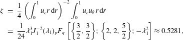
yields a global constant, the present model may be associated with a subclass of Beltramian motions known as Trkalian (Majdalani Reference Majdalani2012). Moreover, given the helical nature of the flow field, its swirl intensity, which represents a measure of the axial flux of tangential angular momentum relative to the axial flux of axial momentum, may be readily evaluated using, for example, the definition provided by Chang & Dhir (Reference Chang and Dhir1995),
 $$\begin{eqnarray}\displaystyle \unicode[STIX]{x1D701} & = & \displaystyle \frac{1}{4}\left(\int _{0}^{1}u_{z}r\,\text{d}r\right)^{-2}\int _{0}^{1}u_{z}u_{\unicode[STIX]{x1D703}}r\,\text{d}r\nonumber\\ \displaystyle & = & \displaystyle \frac{1}{24}\unicode[STIX]{x1D706}_{1}^{3}J_{1}^{-2}(\unicode[STIX]{x1D706}_{1})_{p}F_{q}\left[\left\{\frac{3}{2},\frac{3}{2}\right\}\!;\left\{2,2,\frac{5}{2}\right\}\!;-\unicode[STIX]{x1D706}_{1}^{2}\right]\approx 0.5281,\end{eqnarray}$$
where
 $_{p}F_{q}$
stands for the generalized hypergeometric function. In the present case, the swirl intensity is found to be axially invariant, mainly because of the equally linear spatial dependence of both
 $u_{z}$
and
 $u_{\unicode[STIX]{x1D703}}.$
Lastly, the pressure distribution may be retrieved from Euler’s momentum equation, whose partial integration and subsequent recombination render
 $$\begin{eqnarray}\displaystyle \unicode[STIX]{x0394}p=p-p_{0} & = & \displaystyle \frac{u_{h}^{2}\unicode[STIX]{x1D706}_{1}^{2}-J_{1}^{2}(\unicode[STIX]{x1D706}_{1}r)-(z+u_{h})^{2}\unicode[STIX]{x1D706}_{1}^{2}[J_{0}^{2}(\unicode[STIX]{x1D706}_{1}r)+J_{1}^{2}(\unicode[STIX]{x1D706}_{1}r)]}{2J_{1}^{2}(\unicode[STIX]{x1D706}_{1})}\nonumber\\ \displaystyle & {\approx} & \displaystyle 1.8552\{5.7832u_{h}^{2}-J_{1}^{2}(\unicode[STIX]{x1D706}_{1}r)-5.7832(z+u_{h})^{2}[J_{0}^{2}(\unicode[STIX]{x1D706}_{1}r)+J_{1}^{2}(\unicode[STIX]{x1D706}_{1}r)]\},\nonumber\\ \displaystyle & & \displaystyle\end{eqnarray}$$
where
 $p_{0}\equiv p(0,0).$
In the next section, these parameters will be compared with their corresponding TC values.
3.4 Comparison with the TC and Hart–McClure mean flows
We begin by displaying the streamlines associated with the Trkalian and complex-lamellar profiles in figures 5(a) and 5(b) for
 $u_{h}=0$
and 0.5, respectively. The second case corresponds to a headwall injection speed that mimics reactive flow conditions in a simulated SRM with a regressing propellant grain at the forward closure. In order to produce the same mass flow rate per unit area as that occurring along the sidewall, one can take
 $$\begin{eqnarray}\int _{0}^{a}\bar{u}_{z}(2\unicode[STIX]{x03C0}\bar{r})\,\text{d}\bar{r}=\unicode[STIX]{x03C0}a^{2}U_{w}\quad \text{or}\quad 2\unicode[STIX]{x03C0}u_{h}\int _{0}^{1}\unicode[STIX]{x1D706}_{1}J_{0}(\unicode[STIX]{x1D706}_{1}r)J_{1}^{-1}(\unicode[STIX]{x1D706}_{1})r\,\text{d}r=\unicode[STIX]{x03C0}.\end{eqnarray}$$
This leaves us with
 $u_{h}=0.5$
, the same value that permits the similarity-conforming half cosine pattern to mimic reactive flow conditions in the TC configuration (Abu-Irshaid et al.
Reference Abu-Irshaid, Majdalani and Casalis2007). It should be noted that the streamtube motion that accompanies headwall injection becomes increasingly more pronounced with successive increases in
 $u_{h}$
. Also shown on the graph are the TC streamlines, and these are seen to exhibit faster flow turning than the present solution. The reason for the steeper TC curvature may be attributed to its faster axial velocity and less appreciable radial contribution near the sidewall. These conditions lead to a delayed flow turning in the Trkalian configuration. Naturally, the crisp similarity patterns depicted in figure 5(a) are quickly overtaken by an essentially streamtube motion in figure 5(b). Although not shown, values of
 $u_{h}\in [40,100]$
, such as those ascribed to hybrid rocket operation, give rise to a fully developed streamtube motion that is pervasive everywhere, except for the sidewall region.
Comparison between the Trkalian streamlines and those corresponding to the TC solution for a simulated SRM (a) without and (b) with headwall injection. The latter mimics the case of uniform burning at the headwall.

In practice, the flow turning angle
 $\unicode[STIX]{x1D703}$
may be defined as the slope of the local velocity measured from the wall-normal direction. Its geometric formulation,
 $\unicode[STIX]{x1D703}(r)=\tan ^{-1}[-u_{z}/(zu_{r})]$
, is plotted in figure 6(a) alongside the TC flow turning angle and that of Hart–McClure. The latter corresponds to a potential mean flow profile,
 $\boldsymbol{u}=-r\boldsymbol{e}_{r}+2z\boldsymbol{e}_{z}$
, which has been historically adopted by Hart & McClure (Reference Hart and McClure1959) as well as other researchers, to model the bulk gaseous motion in SRMs, before the advent of the TC base flow. The reader may consult in this regard the work of McClure, Hart & Cantrell (Reference McClure, Hart and Cantrell1963). As shown by Saad & Majdalani (Reference Saad and Majdalani2010), the Hart–McClure (HM) profile constitutes the state of least kinetic energy, unlike the present formulation, which possesses more energy than its TC predecessor. Starting with
 $\unicode[STIX]{x1D703}$
in figure 6(a), one may infer that the flow entering the chamber has no parallel component at
 $r=1$
, where
 $\unicode[STIX]{x1D703}=0^{\circ }.$
In contrast, the onset of parallel motion at
 $r=0$
may be deduced in the three cases considered due to
 $\unicode[STIX]{x1D703}(0)=90^{\circ }$
. As we examine the region extending from the sidewall to the centreline, the HM motion is accompanied by the most abrupt variation in
 $\unicode[STIX]{x1D703}$
. In contrast, the turn angle associated with the Trkalian model changes relatively slowly. The smoother gradients near the sidewall signal the presence of a more energetic motion, which is typically accompanied by a sharper radial velocity. These trends are confirmed in figure 6(b,c), where the Trkalian flow may be seen to exhibit the smoothest radial and axial velocities at any radial position.
In figure 6(b), for example, the Trkalian
 $u_{r}$
may be seen to achieve the largest peak velocity of 1.121 (in absolute value), which constitutes a 12.1 % overshoot relative to the normalizing sidewall injection speed. This overshoot reaches its peak at
 $r=0.7656$
, and is required to compensate for the decreasing tubular area
 $(2\unicode[STIX]{x03C0}rL)$
, which evolves in the normal direction to the incoming stream. Alternatively, the TC radial velocity exhibits a 6.7 % overshoot at
 $r=0.861$
, which is approximately half as large, and occurs at a wider radius. In contrast, by examining the HM case with least kinetic energy, it may be realized that no overshoot may be accrued in a top-hat profile. Instead,
 $\left|u_{r}\right|$
decreases linearly from a value of unity at the wall to a mere zero at the centreline. This linear variation is accompanied by a uniform axial velocity, as depicted in figure 6(c). Therein, the axial velocities of the three models in question are compared, and these range from the steepest HM model, to the cosine-shaped TC velocity, and, lastly, to the Bessel-smooth Trkalian profile.
Comparison of the Trkalian, TC and HM profiles. Results are shown for (a) the streamline turning angle, (b) the radial velocity and (c) the axial velocity.

As we cross beyond the TC threshold, the centreline velocity may be seen to increase with the underlying kinetic energy, and this behaviour may be attributed to the need for
 $u_{c}$
to evolve in compliance with mass conservation, which is simply given by
 $Q=2\unicode[STIX]{x03C0}\int _{0}^{1}u_{z}r\,\text{d}r=2\unicode[STIX]{x03C0}z$
. To this end, the centreline speed of each model must stretch in such a manner as to preserve the total volumetric flow rate
 $Q$
. While the lowest
 $u_{c}$
appears in the spatially uniform distribution, the highest speed is realized with the Trkalian profile, which overshoots the HM and TC models by 2.316 and 1.474, respectively. This increase in kinetic energy, which is accompanied by an axial increase in the swirl velocity, leads to a faster depreciation in the pressure along the centreline.
By way of confirmation, a side-by-side comparison of the axial velocities and total mean flow vorticities of both the Trkalian and TC models is furnished in figures 7(a) and 7(b), respectively. These are provided at six equally spaced distances from the headwall assuming
 $u_{h}=0.$
In both graphs, it may be seen that the Trkalian formulation exhibits higher velocities and vorticities in the core region, but lower velocities and vorticities near the sidewall. In contrast, the TC model appears to be virtually irrotational in the core region, as most of its vorticity is generated at the sidewall and then quickly attenuated as the centreline is approached. This behaviour is contrary to that of the Trkalian vorticity, which begins with a finite value at the sidewall, where the magnitude of
 $\unicode[STIX]{x1D734}_{w}=-\unicode[STIX]{x1D706}_{1}\boldsymbol{e}_{r}+(z+u_{h})\unicode[STIX]{x1D706}_{1}^{2}\boldsymbol{e}_{\unicode[STIX]{x1D703}}$
starts at
 $\unicode[STIX]{x1D706}_{1}[1+(z+u_{h})^{2}\unicode[STIX]{x1D706}_{1}^{2}]^{1/2}$
, and then increases to
 $(z+u_{h})\unicode[STIX]{x1D706}_{1}^{2}J_{1}^{-1}(\unicode[STIX]{x1D706}_{1})$
at the centreline, where the vorticity becomes solely axial due to the non-vanishing swirl velocity gradient,
 $\unicode[STIX]{x1D734}_{0}=(z+u_{h})\unicode[STIX]{x1D706}_{1}^{2}J_{1}^{-1}(\unicode[STIX]{x1D706}_{1})\boldsymbol{e}_{z}$
. It may be instructive to note that the centreline vorticity will exceed the sidewall vorticity as long as
 $\Vert \unicode[STIX]{x1D734}_{0}\Vert >\Vert \unicode[STIX]{x1D734}_{w}\Vert$
or
 $(z+u_{h})\geqslant J_{1}(\unicode[STIX]{x1D706}_{1})/[\unicode[STIX]{x1D706}_{1}^{2}-\unicode[STIX]{x1D706}_{1}^{2}J_{1}^{2}(\unicode[STIX]{x1D706}_{1})]^{1/2}$
. Thus, granted that
 $(z+u_{h})\geqslant 0.252581$
, vorticity will asymptote to a higher value in the core region, where its magnitude (which becomes virtually independent of the radial position) will continue to increase in the downstream direction according to (3.17). Interestingly, in reference to figure 7(b), a special situation arises when
 $(z+u_{h})<0.252581,$
as the vorticity magnitude at the centreline will depreciate below its wall value due to the weaker swirl contribution in the forward section of the chamber. These observations are further confirmed in figure 8, where the isovorticity contour lines for the two inviscid models are stacked side-by-side with and without headwall injection. In both configurations, the trend reversal in the vorticity distributions associated with the TC and Trkalian profiles is clearly seen and captured by the crossing angle between their isolines. In the presence of headwall injection, the prevalent streamtube motion affecting the streamline patterns in figure 5(b) seems to be equally mirrored in the isovorticity lines.
Comparison between the present Trkalian solution and the TC model for (a) the axial velocity and (b) the total vorticity for a simulated SRM with no headwall injection. Both panels share the same legend.

Comparison between the Trkalian isovorticity contours (full lines) and those of the TC solution (chain lines) for a simulated SRM (a) without and (b) with headwall injection.

As for the pressure field, its axial distribution along the centreline, which may be determined from (3.19), is plotted in figure 9(a) alongside those of the HM and TC profiles. The corresponding axial pressure gradient is also illustrated in figure 9(b), where it is shown to increase both in the downstream direction and inwardly as the centreline is approached. Compared with its preceding models, the Trkalian pressure drop exceeds those of the HM and TC profiles at the aft end of the chamber by an appreciable amount, namely by factors of 2.63 and 2.13, respectively. This noticeable pressure depreciation is necessary to offset the greater increase in flow kinetic energy in the presence of higher axial, radial and tangential velocity contributions relative to the HM and TC formulations. It is also corroborated by industrial observations such as those cited by Clayton (Reference Clayton1996).
Comparison between the Trkalian pressure drop and those associated with the TC and HM solutions for a simulated SRM with no headwall injection. We also show in (b) the axial pressure gradients associated with the Trkalian motion at equally spaced increments from the headwall.

3.5 Numerical verification
The flow field described heretofore may be confirmed using a numerical simulation of the corresponding inviscid solution and a similarity-conforming headwall injection profile that is consistent with (3.16) and (3.19). For this purpose, a pressure-based finite-volume solver is employed in conjunction with an axisymmetric geometric configuration that permits the evolution of swirl along a structured cylindrical mesh. Starting with profile-conforming velocity injection functions at the headwall and sidewall regions, as well as a solution-conforming initialization field, convergence to the exact Trkalian mean flow is achieved across the domain with variances between analytical and numerical predictions that do not exceed 0.4 %. In this case, a non-zero
 $u_{\unicode[STIX]{x1D703}}$
is imposed at the sidewall, consistently with the swirling Trkalian profile. Our simulations correspond to a right-cylindrical porous tube of 1 m radius and 8 m length, thus leading to an aspect ratio of
 $L=8$
. An extra allowance of two additional metres downstream of the zone of interest is given to permit the flow to further develop, thereby avoiding edge effects that can accompany a pressure outflow boundary condition. As shown in figure 10, the mesh extends over 384 360 cells that are distributed along a 10 m long cylindrical region that is further seeded with 113 105 equally spaced points. While the SIMPLE algorithm is relied upon to couple the pressure and velocity fields, the Green–Gauss node-based gradient evaluation is used for spatial discretization. Furthermore, the PRESTO pressure interpolation scheme, which stands for ‘PREssure STaggering Option,’ is selected to better accommodate the helical flow development by staggering the grid. Finally, a third-order MUSCL scheme, which refers to the ‘Monotonic Upstream-Centered Scheme for Conservation Laws,’ is chosen to interpolate for the momentum and swirl velocities (van Leer Reference van Leer1979).
Graphical depiction of the structured mesh used in the finite-volume solver.

Comparison of the exact Trkalian solution with inviscid computational fluid dynamics (CFD) simulations corresponding to (a) axial, (b) tangential and (c) radial velocity distributions at five equally spaced stations as well as (d) the centreline pressure drop.

Our computations for an initial wall velocity of
 $U_{w}=1~\text{m}~\text{s}^{-1}$
are presented in figure 11, where comparisons between analytical and numerical predictions of the three component velocities are provided at five evenly spaced axial stations spanning the established length of the chamber. Additionally, the pressure drop is computed along the centreline and compared with the present formulation. It is gratifying to note the excellent agreement between theory and computations, especially in the radial velocity estimation, which is confirmed to be axially invariant by the finite-volume solver in figure 11(c), as well as the pressure depreciation and its spatial dependence in figure 11(d).
4 Conclusions
In this work, an Euler solution is presented as a prospective flow candidate for describing the internal gaseous motion in uniquely spinning rocket motors with either a similarity-conforming headwall injection profile or a sealed headwall. Following tradition, a perfect motor is idealized as a right-cylindrical chamber with a permeable sidewall and either finite or infinite headwall impedance. In this study, the BHE in cylindrical coordinates is used to establish a steady-state model for solid and hybrid motors, where the hybrid configuration may be characterized by a large headwall-to-sidewall injection ratio. The resulting solution may be viewed as a theoretical complement to the frequently cited TC motion, which stems from the virtually equivalent vorticity–streamfunction approach. Furthermore, the swirling profile may be recognized as a natural companion to the cyclonic mean flow known colloquially as the bidirectional vortex, which develops in the context of a right-cylindrical chamber. Although its inception is connected with the modelling of solid and hybrid rocket internal ballistics, particularly those exhibiting a well-prescribed swirling motion, the basic solution that we obtain can be modified and extended to problems involving paper manufacture, drainage of watery suspensions, isotope separation and boundary layer control. In comparison with the TC formulation, where the tangential motion is suppressed, the angular momentum associated with the Trkalian model is granted the freedom to change with the streamfunction, a property that is often imposed in deriving similarity solutions with three non-vanishing velocity components. Compared with the TC flow structures, specific differences may be noted in the minimum radial and maximum axial velocities, vorticities and pressure distributions. The main distinction of the Trkalian profile may be attributed to its higher kinetic energy and centreline speed, to its tangential velocity exhibiting a linear dependence on the streamwise coordinate and to its finite vorticity in all three spatial directions. In the absence of experimental data for this idealized motor, the solution is verified numerically, using a finite-volume solver. From an academic standpoint, it is hoped that the Trkalian model will promote further interest in the characterization of helical flows in rocket motors, especially those of the TC type, which have been frequently employed in modelling the internal motion associated with non-swirling rocket chambers.
Acknowledgements
This work is supported partly by the National Science Foundation and partly by the Hugh and Loeda Francis Chair of Excellence, Department of Aerospace Engineering, Auburn University. A.F. was a Research Associate of Dr J. Majdalani at the time this work was undertaken. We also thank O. M. Cecil for his useful suggestions.
Supplementary material
Supplementary material is available at https://doi.org/10.1017/jfm.2017.342.


 Open access

