Introduction
Materials used in wearable and implantable bioelectronic devices need to be soft and deformable to form intimate mechanical interfaces with biological tissue to enable effective biochemical and physical sensing, delivery of localized therapeutics, and restoration of damaged tissues. Reference Someya, Bao and Malliaras1–Reference Lipomi and Bao3 These types of deformable sensors and power sources, combined with soft actuators, permit soft robotic devices that can both “feel” and move, and could lead to integrated wearable devices that can provide tactile or kinesthetic cues to the user.
The content of this article is based on scientific progress presented and discussed at the MRS/Kavli Future of Materials Workshop on “Flexible and Stretchable Bioelectronics,” which was held after the 2017 MRS Spring Meeting. This article covers biological integration of soft electronic materials, materials and mechanics, and soft robotics, and concludes with a discussion on the outlook and future challenges associated with the field. Bioelectronics is admittedly a large field with a long history. We restrict our attention, in the interest of space, to bioelectronic devices whose key characteristic is mechanical deformability, which were the subject of this workshop.
Rigid to Stretchable: Challenges
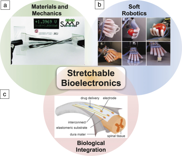
There are several challenges associated with creating stretchable bioelectronics, such as unwanted changes in the electrical properties resulting from deformation, mechanical mismatches between materials, integrating sources of power, and environmental stability. To elaborate on the first of these challenges, most materials exhibit an incidental change in electrical conductivity in response to strain and change in temperature—stretching an isotropic conductor produces an increase in resistance. Likewise, most materials have a nonzero temperature coefficient of resistance. Therefore, a challenge in stretchable electronics is to produce stretchable wiring whose resistance is invariant with strain and temperature. Reference Marin, Root, Urbina, Aklile, Miller, Zaretski and Lipomi4,Reference Lee, Kang, Gwon, Choi, Lim, Sun and Joo5 Materials intended to have a strain response can measure voluntary motions, including facial expressions and involuntary motions, such as pulse and respiration. Reference Kano, Kim and Fujii6–Reference Chen and Pei9 Other mechanisms of detecting motion and pressure include capacitive sensing and resonant frequencies of patterned metals. Wearable devices may also measure other physical signals such as forms of electromagnetic radiation (i.e., visible light and UV radiation). Reference Khiabani, Soeriyadi, Reece and Gooding10–Reference Gomelsky12 Finally, these materials may be utilized as wearable or implantable energy harvesting devices, such as a stretchable battery (as shown in Figure 1a). Reference Kettlgruber, Kaltenbrunner, Siket, Moser, Graz, Schwödiauer and Bauer13
A Venn diagram shows the organization of stretchable bioelectronics into three categories: (a) materials and mechanics, (b) soft robotics, and (c) biological integration. (a) Illustration of stretchable rechargeable battery using hydrogel and conductive paste. Reproduced with permission from Reference Reference Kettlgruber, Kaltenbrunner, Siket, Moser, Graz, Schwödiauer and Bauer13. © 2013 Royal Society of Chemistry. (b) Soft robotic gripper that uses an optical signal feedback to sense and handle soft and fragile objects. Reprinted with permission from Reference Reference Zhao, O’Brien, Li and Shepherd69. © 2016 AAAS. (c) Soft device, called “e-dura,” which is implanted into damaged spinal tissue to restore its function. The device consists of a patterned microfluidic device that enables drug delivery and soft and flexible electrodes to transmit an electrical signal and excite surrounding nervous tissue. Reprinted with permission from Reference Reference Minev, Musienko, Hirsch, Barraud, Wenger, Moraud, Gandar, Capogrosso, Milekovic, Asboth, Torres, Vachicouras, Liu, Pavlova, Duis, Larmagnac, Vörös, Micera, Suo, Courtine and Lacour15. © 2015 AAAS.

Biological integration
Biological integration refers to wearable and implantable devices that monitor physiological activities, Reference Kim, Lu, Ma, Kim, Kim, Wang, Wu, Won, Tao, Islam, Yu, Kim, Chowdhury, Ying, Xu, Li, Chung, Keum, McCormick, Liu, Zhang, Omenetto, Huang, Coleman and Rogers14–Reference Kim, Cho, Cho, Qiao, Rhim, Soh, Kim, Choi, Choi, Park, Hwang, Hyeon, Choi, Lu and Kim16 either sense or regulate biochemical and metabolic processes, Reference Kalantar-zadeh, Ha, Ou and Berean17 or deliver drugs. Reference Son, Lee, Qiao, Ghaffari, Kim, Lee, Song, Kim, Lee, Jun, Yang, Park, Shin, Do, Lee, Kang, Hwang, Lu, Hyeon and Kim18–Reference Reineke21 Biological systems also provide inspiration for new sensing and actuating mechanisms. For example, mechanoreceptors in the skin convert pressure into an AC signal that is registered in the brain as touch. Similarly, this concept has been demonstrated using printed organic pressure sensors and other circuit elements on thin plastic foils. Using techniques of optogenetics, it was possible to transmit this signal to simulate neurons in vitro. Sensors from this work and others show promise for integrating touch sensation and feedback to damaged limbs or prosthetics. Reference Minev, Musienko, Hirsch, Barraud, Wenger, Moraud, Gandar, Capogrosso, Milekovic, Asboth, Torres, Vachicouras, Liu, Pavlova, Duis, Larmagnac, Vörös, Micera, Suo, Courtine and Lacour15,Reference Tee, Chortos, Berndt, Nguyen, Tom, McGuire, Lin, Tien, Bae, Wang, Mei, Chou, Cui, Deisseroth, Ng and Bao22 An example of a flexible device implanted into spinal tissue is shown in Figure 1c.
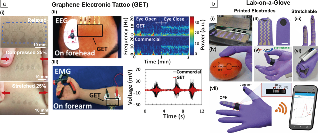
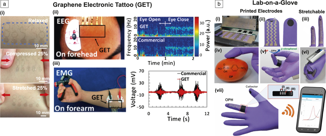
Devices worn directly on the body need to be thin (or inherently soft) to conform to the topography of the skin. Devices meeting this criterion have been called epidermal electronics. Reference Kim, Lu, Ma, Kim, Kim, Wang, Wu, Won, Tao, Islam, Yu, Kim, Chowdhury, Ying, Xu, Li, Chung, Keum, McCormick, Liu, Zhang, Omenetto, Huang, Coleman and Rogers14 Such conformal devices can measure a range of physical and chemical signals. Epidermal electronic devices also contain antennas that transmit data to mobile phones and computers to provide instantaneous and real-time monitoring. Reference Rogers, Ghaffari and Kim2 Thin and transparent devices worn directly atop the skin are also called electronic tattoos. Figure 2a shows electronic tattoos made from graphene that monitor heart and brain activity, the results of which were on par with commercial sensors. Reference Kabiri Ameri, Ho, Jang, Tao, Wang, Wang, Schnyer, Akinwande and Lu23
(a) Graphene is printed onto a thin, flexible polymer to form (i) a transparent electronic tattoo. The serpentine pattern of the graphene traces allows it to function while undergoing deformations. The top image shows the tattoo in its relaxed state. Due to the elasticity of the tattoo and skin, the tattoo can function while being compressed (middle) or stretched (bottom). The tattoo sensor can monitor physiological activities, (ii) electroencephalogram (EEG), (iii) electromyogram (EMG). The EEG sensor is placed on the forehead (ii, left) to measure neurophysiological activities such as (right) blinking of eyelids. (iii, left) The EMG sensor is placed on the forearm to show sensing of muscle movements, such as hand clenching. A common commercial sensor is placed nearby the tattoo sensor to benchmark the performance. (Right) The accuracy of the tattoo sensors and commercial sensors are similar. Adapted with permission from Reference Reference Kabiri Ameri, Ho, Jang, Tao, Wang, Wang, Schnyer, Akinwande and Lu23. © 2017 American Chemical Society. (b[i]) Three individual electrodes are screen printed onto a nitrile glove to (ii) serve as a traditional three-electrode electrochemical cell (ii). Scale bar = 10 mm. (Left, ii) The three electrodes are printed onto the index finger. (Right, ii) The thumb contains a collector pad that accumulates or gathers the chemical or biomarker of interest. The collector pad contains immobilized enzyme (OPH) that reacts with the biomarkers. (iii) The electrodes are printed on a glove, and the sensors are flexible and stretchable up to 50% of its original length. Scale bar = 10 mm. The electrodes sense electrochemical reactions with (iv) biomarkers and (v) chemicals based on a change in current. (vi) A portable potentiostat is placed onto the back of the hand and wirelessly transmits a voltamogram to (vii) a mobile device. The inset of (vii) shows (I and II) the three electrode pins that are placed on (III) an adjustable Velcro ring. Adapted with permission from Reference Reference Mishra, Hubble, Martín, Kumar, Barfidokht, Kim, Musameh, Kyratzis and Wang34. © 2017 American Chemical Society. Note: OP, organophosphate; OPH, organophosphate hydrolyase; R, any chemical group containing a hydrocarbon that is attached to the chemical functional group.
MC-10, Inc., which commercializes epidermal electronics, recently announced a disposable patch that uses UV-sensitive dyes to monitor sun exposure; this patch is made in partnership with L’Oreal. Reference Gomelsky12 The patch wirelessly transmits data to the wearer’s mobile phone. Closely related to epidermal electronics is imperceptible electronics. Reference Kaltenbrunner, Sekitani, Reeder, Yokota, Kuribara, Tokuhara, Drack, Schwödiauer, Graz, Bauer-Gogonea, Bauer and Someya24,Reference Drack, Graz, Sekitani, Someya, Kaltenbrunner and Bauer25 While the difference between these terms is not distinct, the latter emphasizes the mechanical invisibility of devices when worn on the skin. Recently, the development of “imperceptible electronics,” which compose organic circuitry on ultrathin plastic foils (∼2 µm), allows such devices to function even under bending radii of <50 µm. Reference Kaltenbrunner, Sekitani, Reeder, Yokota, Kuribara, Tokuhara, Drack, Schwödiauer, Graz, Bauer-Gogonea, Bauer and Someya24,Reference Drack, Graz, Sekitani, Someya, Kaltenbrunner and Bauer25
While sensors of physical stimuli have a ubiquitous presence in the wearable electronics community, a new vein of research is emerging that focuses on sensing chemical signals, including biochemical markers. For example, collecting and sensing analytes in sweat Reference Sonner, Wilder, Gaillard, Kasting and Heikenfeld26–Reference Heikenfeld28 or blood, Reference Sonner, Wilder, Heikenfeld, Kasting, Beyette, Swaile, Sherman, Joyce, Hagen, Kelley-Loughnane and Naik29 in a minimally invasive or noninvasive manner, are growing in popularity. Similarly, sensing volatile organic compounds and toxic gases is important for monitoring environmental health. Reference Kim, Kim, Kim, Shim, Kim, Hong and Jang30,Reference Kim, Alrowais, Kim, Yeon, Ghovanloo and Brand31 Some recent encouraging results include organic thin films containing catalytic particles that are capable of detecting disease markers in the breath. Reference Zhang, Qu, Mohammadi, Mei and Diao32
Alternatively, electrochemical reactions can be useful for monitoring levels of glucose, alcohol, and electrolytes. Reference Gao, Emaminejad, Nyein, Challa, Chen, Peck, Fahad, Ota, Shiraki, Kiriya, Lien, Brooks, Davis and Javey33 One approach involves screen printing conductive inks and pastes onto textiles or thin polymers to form electronic tattoos. Reference Kabiri Ameri, Ho, Jang, Tao, Wang, Wang, Schnyer, Akinwande and Lu23 Devices that are integrated with textiles can withstand numerous laundry cycles of washing and drying. The printed material consists of carbon or silver electrodes with immobilized enzymes to sense compounds of interest. Similarly, Figure 2b demonstrates a “lab-on-glove” system—a glove with printed sensors to detect harmful chemical agents or allergens, or identify different objects. Reference Mishra, Hubble, Martín, Kumar, Barfidokht, Kim, Musameh, Kyratzis and Wang34 There is hope that such soft and stretchable electrochemical sensors may eventually interface directly with the nervous system. Reference Kettlgruber, Kaltenbrunner, Siket, Moser, Graz, Schwödiauer and Bauer13,Reference Minev, Musienko, Hirsch, Barraud, Wenger, Moraud, Gandar, Capogrosso, Milekovic, Asboth, Torres, Vachicouras, Liu, Pavlova, Duis, Larmagnac, Vörös, Micera, Suo, Courtine and Lacour15,Reference Lacour, Courtine and Guck35
Materials and mechanics
The development of materials that combine state-of-the-art electronic properties with mechanical softness, along with biocompatibility, is central to stretchable bioelectronics. Elastomers (e.g., silicone rubber, thermoplastic polyurethane, and natural silk fibroin) and hydrogels (e.g., polyacrylamide) often comprise the bulk of stretchable bioelectronics devices because they are soft (Young’s modulus <10 MPa) and easy to process. There have been considerable efforts to develop soft conductive materials that are also highly stretchable, including a conductor with up to 1000% stretchability. Reference Cai, Wang, Qian, Chen, Li and Lee36 For most biological applications, however, stretchability commensurate with that of human skin (strain ≤50%) is probably sufficient. Thus, the remarkable progress made in achieving high stretchability in conductive composites suggests that other goals may take priority. These goals include, but are not limited to, improving electrical conductivity, developing intrinsically stretchable semiconductors, improving adhesion and strain relief at dissimilar interfaces, and achieving energy-harvesting capabilities.
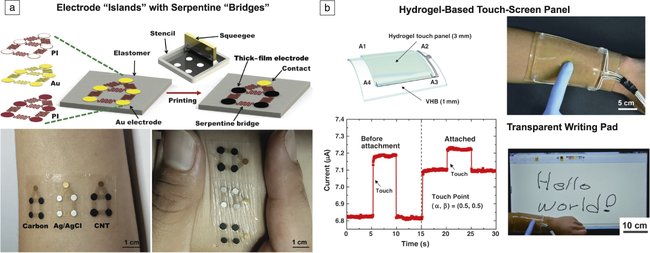
There are several strategies to achieve stretchable conductors. A common strategy is to create composite materials of elastomers and conductive fillers, such as carbon nanomaterials or silver nanowires. However, there are several disadvantages to using composites, including lower conductivity than metals and hysteresis from stretching. Reference Lipomi37 Another approach is to pattern conductive traces into serpentine shapes around rigid electronic components (i.e., capacitors or transistors). Reference Kim, Song, Choi, Kim, Kim, Liu, Huang, Hwang, Zhang and Rogers38 Upon stretching, the serpentine patterns straighten out to maintain electrical conductivity. Figure 3a shows an example of serpentine electrodes. Reference Mohan, Kim, Gu, Bandodkar, You, Kumar, Kurniawan, Xu and Wang39 Both composite materials and those with serpentine traces have finite limits of extensibility (i.e., maximum strain before loss of conductivity). Alternatively, one may use intrinsically stretchable conductors, such as organic conductors (e.g., conjugated polymers). Reference Lipomi and Bao3,Reference Root, Savagatrup, Printz, Rodriquez and Lipomi40–Reference Chung and Diao43
Materials and mechanics. (a) (Top) A wearable tattoo sensor is composed of screen-printed metal contacts (islands) with serpentine-shaped bridges. (Bottom, left) Several types of conductor materials (carbon, Ag/AgCl, and CNT) can be screen printed. (Bottom, right) The serpentine bridges serve as stretchable interconnects. Adapted with permission from Reference Reference Mohan, Kim, Gu, Bandodkar, You, Kumar, Kurniawan, Xu and Wang39. © 2017 Wiley. (b) A hydrogel piece mounted on (top, left) of 3M very high bond (VHB) film is utilized as a (top, right) wearable transparent, conductive touch screen. The touch sensing mechanism works based on change in (bottom, left) current. The authors demonstrate a (bottom, right) touch-screen for writing, playing music (not shown), or games (not shown). Reprinted with permission from Reference Reference Kim, Lee, Oh and Sun50. © 2016 AAAS. Note: CNT, carbon nanotube; A1–A4, separate current collectors that provide the location and sensitivity of the touch point; α, β, normalized Cartesian coordinates on the hydrogel touch panel.
Similarly, room-temperature liquid metals, especially eutectic alloys of gallium, are also promising soft conductors. Reference Dickey44,Reference Kazem, Hellebrekers and Majidi45 These classes of metals possess low toxicity, display higher electrical conductivities than composites, and are softer than biological tissues. Due to their fluidic nature, they retain conductivity while undergoing large deformations and are self-healing. However, gallium diffuses into many metals, which poses a materials challenge for long-term use. Reference Dickey44–Reference Kramer48
A new form of stretchable conductor has recently emerged based on ionic hydrogels. Reference Keplinger, Sun, Foo, Rothemund, Whitesides and Suo49 Hydrogel materials are well-suited for implantable devices because they are soft and biocompatible. Like biological systems, hydrogels transduce signals over long distances using ions. While optical transparency is difficult to achieve in conventional electronic conductors, ionically conductive hydrogels are inherently transparent because they comprise mostly water. Reference Keplinger, Sun, Foo, Rothemund, Whitesides and Suo49 Figure 3b demonstrates transparent touch-screen panels that register pressure through changes in capacitance. Reference Kim, Lee, Oh and Sun50 Recent studies have attempted to increase the stretchability and toughness of ionic hydrogels and also to render them self-healing. Reference Cai, Wang, Qian, Chen, Li and Lee36,Reference Ma, Lee, Han, Oh, Nam and Sun51–Reference Odent, Wallin, Pan, Kruemplestaedter, Shepherd and Giannelis57
A major challenge with ionically conductive devices is that they are limited to a narrow operating voltage due to electrochemical reactions that can take place within the material. Moreover, ionic systems also suffer from large impedances at interfaces with metals; likewise, corrosion is also a risk at this interface. Fortunately, there has been progress on overcoming issues with electrochemical reactions at the hydrogel–electrode interface. This involves placing a dielectric capacitor in series with the hydrogel to lower the voltage across the hydrogel–electrode interface. Reference Keplinger, Sun, Foo, Rothemund, Whitesides and Suo49 This approach has enabled transparent ionic actuators, which can also be useful for soft robotics.
Mismatch of mechanical properties at the interface of soft and rigid components is an ongoing challenge. Various approaches have been developed to reduce the strain at interfaces. Notably, serpentine patterns minimize strain on “islands” of rigid components. When patterned onto prestrained elastomers, the two-dimensional serpentine structures transform into three-dimensional (3D) buckled structures to improve stretchability. Reference Su, Ping, Yu, Lee, Fan, Wang, Li, Li, Harburg, Huang, Yu, Mao, Shim, Yang, Lee, Armonas, Choi, Yang, Paik, Chang, Dawidczyk, Huang, Wang and Rogers58,Reference Zhang, Wang, Li, Fan, Xu, Song, Choi, Yeo, Lee, Nazaar, Lu, Yin, Hwang, Rogers and Huang59 Another approach to reduce strains at soft–rigid interfaces is to use modulus gradients that dissipate the buildup of stress; that is, to place several materials of varying elastic modulii at the interface. Reference Naserifar, LeDuc and Fedder60,Reference Libanori, Erb, Reiser, Le Ferrand, Süess, Spolenak and Studart61 However, this approach may add unwanted thickness to a device or complicate processing steps. Adhesion of soft components to a variety of surfaces can also be accomplished using the “super glue” method, which makes it possible to bond hydrogels with elastomers by creating a dispersion of cyanoacrylates with organic solvents. Reference Wirthl, Pichler, Drack, Kettlguber, Moser, Gerstmayr, Hartmann, Bradt, Kaltseis, Siket, Schausberger, Hild, Bauer and Kaltenbrunner62 In addition, bioinspired “adhesives” are gaining popularity, such as the suction cups of cephalopods, Reference Choi, Park, Choi, Qiao, Ghaffari, Kim, Lee, Kim, Hyun, Kim, Hwang, Kwon, Hyeon, Lu and Kim63 van der Waals forces inspired by geckos, Reference Sitti and Fearing64 and catechol chemistry, which are a class of organic functional groups found in many living systems, most notably by mussels. Reference Waite65,Reference Lee and Konst66
Soft robotics
Soft robots are networks of sensors, actuators, and controllers that perform specific tasks. Similar to flexible and stretchable bioelectronic devices, these robots are made of soft materials. This field draws significant inspiration from nature, especially from cephalopods (e.g., octopi and squid). These living organisms are inspirational because they are composed almost entirely of soft materials, can perform tasks (including problem solving), and are autonomously powered. In particular, octopi are interesting because they can alter their skin color and texture on demand to camouflage with their surrounding environment. Reference Laschi, Cianchetti, Mazzolai, Margheri, Follador and Dario67,Reference Anderson, Gisby, McKay, O’Brien and Calius68 Figure 1b Reference Zhao, O’Brien, Li and Shepherd69 shows an example of a soft robot that manipulates or interacts with fragile objects without sophisticated control mechanisms. The force an elastomeric actuator can exert is self-limited by the material itself. Soft robots must be robust to be useful; they should be capable of exerting or receiving large forces without failure. Like octopi, soft robots could also be made to have displays or color outputs that are either static or dynamic, based on the environment, with capabilities of high ON-OFF switching and a range of color. Reference Cai, Wang and Lee70–Reference Morin, Shepherd, Kwok, Stokes, Nemiroski and Whitesides72 Soft robots can also change size and shape to either access “denied spaces” or limit human presence in hazardous environments (such as in search and rescue operations). Finally, it seems likely that devices designed for human–machine interfaces (e.g., androids) will have soft components.
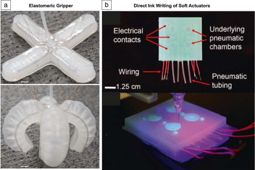
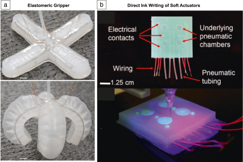
Soft robotics has stimulated the development of several manufacturing technologies. Conventional forms of soft lithography use planar masters with a single level of relief, which are features that appear as protrusions from a background plane (i.e., elastomer with arbitrary heights of protrusions based on a mold). However, a single level of relief may be insufficient to generate complex curvilinear structures. Therefore, recent focus has been on direct-writing and 3D printing of elastomers and hydrogels. Reference Darnell, Sun, Mehta, Johnson, Arany, Suo and Mooney56,Reference Zhao, O’Brien, Li and Shepherd69,Reference Wallin, Pikul, Bodkhe, Peele, Murray, Therriault, McEnerney, Dillon, Giannelis and Shepherd73,Reference Morin, Shevchenko, Lessing, Kwok, Shepherd, Stokes and Whitesides74 For example, Figure 4a shows a recent approach that involves direct ink writing of two different UV-curable inks—one composed of hydrogel and the other silicone-based. Reference Robinson, O’Brien, Zhao, Peele, Larson, Mac Murray, Van Meerbeek, Dunham and Shepherd75 In general, sensors, actuators, and other components of current soft robots are all made of different materials. Fabricating these structures separately and then combining them may be difficult. Recent progress has yielded a two-step method for creating a “monolithic” soft robot. As shown in Figure 4b, such a robot consists of a molded elastomer that is pneumatically actuated. Liquid metal, injected into hollow cavities of the elastomer, serves as a sensor element. Reference Bilodeau, White and Kramer47
Soft robotics. (a) Elastomeric grippers are produced by molding an uncured elastomer. (Top) A gallium alloy liquid metal is injected into hollow cavities of the elastomer to form a monolithic conductive element. (Bottom) A pneumatic feed inflates cavities with air to actuate the gripper. Scale bar = 1.0 cm for both top and bottom images. Reprinted with permission from Reference Reference Bilodeau, White and Kramer47. © 2015 IEEE. (b) Soft pneumatic actuators are fabricated with direct ink writing of two different inks. (Top) A side view image shows the architecture of the soft actuator, which consists of embedded pneumatic chambers with adjacent electrical conductors. Metallic wiring and pneumatic tubing (shown at bottom of image) are embedded within the composite. (Bottom) The two inks (one of conductive hydrogel and the other of an insulating elastomer) are printed in an alternating fashion and cured under UV light. Electrical contacts from metallic wires and tubing for pneumatic control are embedded within the hydrogel material. Reprinted with permission from Reference Reference Robinson, O’Brien, Zhao, Peele, Larson, Mac Murray, Van Meerbeek, Dunham and Shepherd75. © 2015 Elsevier.
There are many opportunities for improving integration of different components of soft robots. For example, a soft robot may comprise many sensors; handling and synchronizing their outputs with better signal processing would improve control systems and automation, and integrating sensing and actuation at the molecular and microstructural level. Actuators and controllers must also enable higher degrees of freedom for motion to endow soft robots with complex movements. Likewise, many soft actuators lack either speed or force of actuation to be useful, especially when compared to soft species in nature (e.g., octopus). Reference Laschi, Cianchetti, Mazzolai, Margheri, Follador and Dario67 Ideally, robots should function autonomously. However, pneumatic pressure lines tether most soft robots for actuation. Therefore, “untethering” robots, perhaps by using miniaturized hydraulics, may improve autonomous function and range of motion. A key challenge to doing so would be to integrate these pumps without compromising the soft structure of the robot.
Outlook and future challenges
There are several important challenges that can be identified with respect to biological integration, materials and mechanics, power sources, and the pathway toward devices that operate in the real world.
Biological integration
Environmental stability of biomaterials is important for long-term use. For example, biological fluids may accelerate degradation, biofouling, or corrosion (e.g., Si leaching) of implantable devices. Likewise, creating a water (either liquid or vapor) barrier around electronics is also vital, but such barriers often change the mechanics of the devices due to their thickness. Within the biosensing research community, monitoring interstitial fluids in a noninvasive manner remains a challenge and an active field of study. Such fluids surround tissues and can provide real-time information on the state of the body, such as stress, or the function of an organ. However, accurate sensing by wearable, noninvasive devices is not easy because of the complexities of biochemistry and variations across individuals, as well as temporal fluctuations of biomarkers in the body. Reference Sonner, Wilder, Heikenfeld, Kasting, Beyette, Swaile, Sherman, Joyce, Hagen, Kelley-Loughnane and Naik29
Integrating soft devices with organs and tissues is also a challenge due to issues with adhesion, especially for “wet” conditions as well as with hydrogels. Reference Li, Celiz, Yang, Yang, Wamala, Whyte, Seo, Vasilyev, Vlassak, Suo and Mooney76 Likewise, reducing artifacts of motion and electromagnetic interference remain challenges for wearable sensors. An emerging area that combines sensing and actuation is haptics—wearable devices that interact with the tactile and kinesthetic senses to provide a more lifelike experience for virtual and augmented reality.
Materials and mechanics
The interfaces of materials are of great significance and there remain many challenges related to interfacial phenomena. A major hurdle within soft and stretchable electronics—not just bioelectronics—is the mechanical mismatch at the interface of soft and hard substrates. For example, the point of failure for most soft devices occurs at the interface of an elastomer and traditional rigid electronics (i.e., printed circuit boards) needed to interface devices with laboratory equipment. Improving the toughness of stretchable materials is one route to increase the durability of materials. Alternatively, the ability of a material to self-heal is also an attractive property. Reference Wallin, Pikul, Bodkhe, Peele, Murray, Therriault, McEnerney, Dillon, Giannelis and Shepherd73,Reference Herbst, Döhler, Michael and Binder77,Reference Binder78 Although many systems exhibit self-healing behavior, future work should focus on improving self-healing such that it is rapid and repeatable even when ruptured multiple times.
Power
Performing functions such as sensing, actuating, haptic feedback (i.e., vibrations or other kinesthetic motions), and transmitting data all require power. Energy sources, whether harvesters or batteries, should be stretchable, durable, and self-healing, and serve continuously for long lifespans, where appropriate. In particular, implantable systems require power sources that are safe and have longevity on the order of tens of years. For example, patients with modern pacemakers often undergo follow-up surgical procedures approximately five to 15 years only to replace the battery. 79 Devices for energy storage include flexible and stretchable batteries, Reference Kettlgruber, Kaltenbrunner, Siket, Moser, Graz, Schwödiauer and Bauer13,Reference Kaltenbrunner, Kettlgruber, Siket, Schwoediauer and Bauer80–Reference Xu, Zhang, Cho, Lee, Huang, Jia, Fan, Su, Su, Zhang, Cheng, Lu, Yu, Chuang, Kim, Song, Shigeta, Kang, Dagdeviren, Petrov, Braun, Huang, Paik and Rogers85 and those for energy harvesting include piezoelectric devices, Reference Qi, Jafferis, Lyons, Lee, Ahmad and McAlpine86–Reference Suarez, Parekh, Ladd, Vashaee, Dickey and Öztürk90 wearable solar “stickers,” Reference O’Connor, Zaretski, Savagatrup, Printz, Wilkes, Diaz, Sawyer and Lipomi91 and wearable biofuel cells that extract energy from sweat. Reference Jia, Valdés-Ramírez, Bandodkar, Windmiller and Wang92,Reference Jia, Wang, Imani, Bandodkar, Ramírez, Mercier and Wang93 Despite recent work on stretchable batteries (as shown in Figure 1a), these batteries are not yet mature for stretchable bioelectronics. Meanwhile, organic solar cells are promising for wearable devices, but not practical for implanted systems. Reference O’Connor, Zaretski, Savagatrup, Printz, Wilkes, Diaz, Sawyer and Lipomi91,Reference Kaltenbrunner, Adam, Głowacki, Drack, Schwödiauer, Leonat, Apaydin, Groiss, Scharber, White, Sariciftci and Bauer94–Reference Lipomi, Tee, Vosgueritchian and Bao96 Finally, the small form factors and the relatively small amount of power available from energy harvesters require transmitters and receivers to operate either with low power Reference Mercier, Lysaght, Bandyopadhyay, Chandrakasan and Stankovic97 or in passive manners. Reference Chen, Tee, Chortos, Schwartz, Tse, Lipomi, Wong, McConnell and Bao98
Creating real-world solutions
There is an inherent motivation in the field of stretchable bioelectronics to create devices that function in the real world. Because this field is relatively new, the onus lies on academic labs to make strides toward transitioning discoveries into real-world solutions. Thus, moving devices from bench spaces to working prototypes should be encouraged by academic and research enterprises. Electronics with a focus on healthcare is of major interest. It was suggested that researchers should engage in more collaborations with the medical community (i.e., physicians, healthcare providers). Researchers should be interested in working with health specialists and take a needs-based approach to the development of technology, as opposed to creating solutions in search of problems.
Conclusion
Conventional electronic devices are made from rigid materials and cannot be easily integrated or implanted with the biological milieu. Because biological tissues are inherently soft and deformable, bioelectronic devices made of soft and stretchable materials are desirable. Beyond comfort, the use of soft electronic materials has the potential to provide more accurate monitoring of physiological activities, such as EEGs and ECGs, by making conformal contact with the skin. Skin itself provides a biological inspiration for soft electronics because skin is stretchable, self-healing, and capable of multimodal sensing; researchers are currently seeking material strategies to mimic these functions. In the case of implanted systems, soft or stretchable bioelectronics offer the ability to monitor the function of organs in real time, regulate metabolic activities, and in some cases, restore function to damaged tissues (i.e., paralyzed limbs or nerves). Likewise, these systems can be integrated with textiles and clothing to enable new wearable platforms. Opportunities remain to improve wearables, thus allowing users to be more proactive with managing their health. For example, future work could focus on sensors that provide more medically relevant information for health monitoring, environmental sensing, and medication compliance. Finally, soft and stretchable materials are important for soft robotic systems that provide greater degrees of freedom of movement relative to conventional robots while using materials and modes of movement that are safe for interfacing with humans. Soft and stretchable electronics, sensors, and actuators are critical to the operation and function of these soft robots. This field is still in its infancy, and current systems are far from mimicking the elegance of biological systems, such as an octopus. In conclusion, we hope this article provides guidance and inspiration for those outside and within the community and serves as a springboard for new ideas, challenges, and opportunities.
Acknowledgments
This report summarizes scientific progress presented and discussed at the MRS/Kavli Future of Materials Workshop on “Flexible and Stretchable Bioelectronics.” This workshop, sponsored by MRS Bulletin and the Kavli Foundation, was held after the 2017 MRS Spring Meeting in Phoenix, Ariz. The purpose of the meeting was to identify trends, challenges, and blind spots in the basic materials science, biological integration, and commercialization for this interdisciplinary field. The authors thank the speakers and panelists at the workshop for their inspirational talks and the attendees for their participation in discussions. D.J.L. acknowledges support from the National Institutes of Health Director’s New Innovator Award 1DP2EB022358-01.

Ishan D. Joshipura is a doctoral candidate of chemical engineering at North Carolina State University. He received his BS degree in chemical engineering at the University of Arizona in 2012, where he was a NASA Space Grant Research Fellow. He received his MS degree in chemical engineering at North Carolina State University in 2015. His research interests include patterning and actuating liquid metals for wearable and reconfigurable electronics. Joshipura can be reached by email at idjoship@ncsu.edu.

Mickey Finn III is a graduate student in the Department of Nanoengineering at the University of California, San Diego, where he also conducted his undergraduate studies. His first author publication, “Mechanical Stability of Roll-to-Roll Printed Solar Cells under Repeated Bending and Torsion” was recently published in Solar Energy Materials and Solar Cells. His current interests include mechanically compliant organic electronics, organic haptics, and alternative nanofabrication approaches. Finn can be reached by phone at 816-204-1694 and or by email at mifinn@eng.ucsd.edu.

Siew Ting Melissa Tan is an undergraduate student in the School of Materials Science and Engineering at Nanyang Technological University (NTU), Singapore. She is a recipient of the Agency for Science, Technology, and Research (A*STAR) Undergraduate Scholarship and is enrolled in the CN Yang Scholars Programme at NTU. She has conducted research at A*STAR, Singapore, and the University of California, San Diego. Her research interests include wearable sensors and actuators for human–machine interfaces. Tan can be reached by phone at +65 8339 2453 or by email at mtan041@e.ntu.edu.sg.

Michael D. Dickey has been an Alumni Distinguished Professor in the Department of Chemical and Biomolecular Engineering at North Carolina State University since 2008. He received his BS degree in chemical engineering from the Georgia Institute of Technology, in 1999, and his PhD degree in chemical engineering from The University of Texas at Austin in 2006. From 2006 to 2008, he was a postdoctoral fellow at Harvard University. His research interests include patterning and actuating soft materials by studying and harnessing thin films, interfaces, and unconventional fabrication techniques. Dickey can be reached by phone at 919-513-0273 or by email at michael_dickey@ncsu.edu.

Darren J. Lipomi is an associate professor in the Department of Nanoengineering at the University of California, San Diego. He earned his PhD degree from Harvard University in 2010, and was a postdoctoral fellow at Stanford University from 2010 to 2012. He is the recipient of the Air Force Office of Scientific Research Young Investigator Award and the NIH Director’s New Innovator Award. His current research focuses on organic semiconductors for stretchable devices. Lipomi can be reached by phone at 858-246-1227 or by email at dlipomi@eng.ucsd.edu.