


Introduction
This paper reports the measurement principle of the image-processing visibility-range monitor, and compares results for visual-range data measured by the trans-missometer with those obtained using the new system. Transmissometers are normally used as visibility-range monitors in blowing snow (Reference Takeuchi and FukuzawaTakeuchi and Fukuzawa, 1985). In our new method, range of visibility is calculated as the distance at which the brightness contrast of a black area and a white area on the target reaches the liminal value, assuming uniformity of the atmosphere. The brightness of the surroundings cannot be considered by the trans-missometer method mentioned above although it affects human sight.
Visibility range has been defined by Koschmieder as the distance at which the brightness contrast of a target with its background has reached the liminal value (Reference MiddletonMiddleton, 1955). Comparisons of visibility data obtained by using a transmissometer with those obtained by using a light meter have been made by Reference Ishimoto and FukuzawaIshimoto and Fukuzawa (1985). The light-meter method posed the problem of keeping the absolutely black area of the target from being affected by the surrounding brightness in order to make possible an evaluation of the physical accuracy of the light meter. The new system we have developed compensates for the effects of the brightness of the surroundings by keeping the absolutely black area within the lens of the video camera.
Instrumentation and Observation
The development of CCD video cameras has made it possible to overcome most of the long-standing operational shortcomings of tube-type video cameras (Reference SadashigeSadashige, 1987) such as distortion of the image due to its position in the visual field and high-light intensity burn-in and after images. The CCD image sensor used in our experiments was composed of an array of 384 × 491 cells which became charged in proportion to the intensity of the illumination of their cells. Thus, the CCD video camera was able to measure the brightness of any chosen area which was visible within its range.
A half-black and half-white plate was used as a target with the CCD camera. The white area of the target represented the surrounding brightness and was so illuminated as to make possible the measurement of visibility at night. The three targets were set up 30 m apart and at heights of 0.45, 1, and 1.2 m above the ground to make possible measurements of visual range at three different levels. These targets were located in parallel with the prevailing wind direction, and were painted with an anti-reflecting paint. The lay-out diagram of the monitoring system is shown in Figure 1. Observations corresponding to a visibility range of 0-999 m could be obtained using output voltages of 1-5 V. Parameters were changed as required by adjustment of the monitor. The lens auto-iris is capable of responding to brightness over the full visual range in order to monitor all possible conditions. The behavior of the auto-iris itself can be monitored by the CCD control unit, which corrects for the effects of surrounding brightness on the brightness of the targets.
During 1987 and 1988, a CCD camera and a transmissometer were set up at a height of 1 m above the snow surface at the blowing-snow observatory station near Sapporo. The light path of the transmissometer was 15 m ahead along the prevailing wind direction from that of the CCD camera. The temperature, wind speed, and wind direction were noted simultaneously in the field. The instrumentation of the video camera and the three targets are shown in Figure 2. All data were recorded using a 16-channel magnetic tape recorder.
In addition to the use of these devices, visibility to the human eye was assessed by using seven black targets of a size equal to half the visual angle from the observation point to the recording apparatus. The measurement sites and the areas of visual observation were changed periodically during the experiment, making it possible to monitor visibility at the same level above the snow surface without changing the position of the camera even when snow depth was changing rapidly, The luminances of the black and white areas of the target plate at the video camera were used to calculate visibility, and were introduced into the system after adjusting for the luminance of the surroundings. A series of revising processes was needed to get accurate visibility data in twilight conditions.
Block diagram of a visibility-range monitor by image processing.

Three targets installed 30 m from the location of the housing case of the CCD video camera and the optical targets within 0.5° of the visual angle from the observation point.

Expression of Visibility Range
The distance of the CCD camera from both the target and the transmissometer was 30 m. This distance was therefore the path length for calculations. The best resolution was obtained at a visibility of around 100 m, since the light-path length should be of the order of one-third of the expected visual range (Reference Ishimoto and FukuzawaIshimoto and Fukuzawa, 1985).
The relationship between visibility and transmissivity is derived from Koschmieder's equation and the Bouger-Lambert law as

and the visibility range detected through the CCD camera is expressed as

where the liminal value for identifying targets (µ) is 0.05; the path length of light (d) is 30 m; T is transmissivity; Cd is the brightness contrast between the white area and the black area on the targets 30 m from the video camera; and CO is the brightness contrast.
In any experiment using this system, the brightness of the plates depends upon a number of other factors in addition to the presence of airborne snow particles, and these additional parameters were used to correct the visibility-range values obtained through the CCD camera. In some cases, automatic correction was made by the automatic iris, and in the others adjustments were made via the keyboard of the parameter-setting monitor. Maximum possible brightness of the white area of the target was allowed for in this way.
The revised algorithm of Equation (2) for considering surrounding brightness is:

where Bb is the brightness of the background; BO is the brightness of the target at the camera position, and Bd is the brightness of the target at d m from it.
A further experimental equation can be obtained for the black area of the target. This is

where Bmax and Bmin are the maximum and minimum values of brightness for the black area of the target. BdO is monitored within the lens of the video camera, and C is the constant to exclude the effect of surrounding brightness. We can monitor the effect of surrounding brightness for values of Bmax = Bmin = 0, and C = −1. We have other algorithms for use in twilight and at night whose formulae we intend to report in our next paper. The algorithm must also be capable of being changed automatically in response to changes in the brightness of the surroundings. One of the daytime analyses which we have made is shown in the next section of this paper, as a means of illustrating the comparison between the visibility data obtained from the CCD video camera and that obtained by use of the transmissometer.
Analysis and Results
The time interval between the readings in the collection of our data was 0.2 s. A typical example of our observa-tions in blowing snow is shown below. The trend in change in visibility with time as observed through the CCD camera was compared with that identified using the transmissometer (Fig. 3).
Because the transmissometer was located 15 m ahead of the video camera in the windward direction, the time lag of the brightnesss fluctuation due to the difference of the location needed to be corrected to allow a precise comparison of the recordings obtained. The cross-correlation
The trend of the visibility by the CCD video camera (A) and that by the transmissometer (B).

Cross-correlation coefficient Rxy(τ) between the visibility by the transmissometer and that by the CCD video camera.

Appearance frequencies of the visibilities measured by the CCD camera at three levels (A, 2 m; B, 1 m; C, 45 cm) over a snow surface in blowing snow.

coefficient between visibility at the CCD camera and visibility at the transmissometer, Rxy(τ), is defined by the equation

where t is time; τ is time lag; X(t) is the visibility fluctuation  recorded by the transmissometer; Y(t) is the visibility fluctuation
 recorded by the CCD video camera, and
 are the instantaneous and the mean ranges of visibility, respectively.
Figure 4 shows the results which were derived from Equation (3), and from these it can be seen that Rxy(τ) has the maximum value of 0.7 at τ = 1.5 s; the mean wind speed at 1 m above the snow surface measured by an ultrasonic anemometer was 10 m/s; air temperature at 1 m height was −4°C; the time lag, τ = 1.5 s, corresponds to the difference in length of the path of light to the transmissometer and that to the video camera; mean wind speed was 10 m/s.
Visibility range at any location is dependent on the presence or absence at any particular levels above the snow surface of blowing snow. In our experiments, targets were located at three different levels A = 2 m, B = 1 m, C = 0.45 m. We have assumed that slow fluctuations in range of visibility are not detectable by the human eye. The intensity of fluctuation in visibility can be calculated using Equation (4) following processing results through a numerical filter that admits only frequencies above 0.1 Hz.
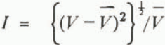
where V is the instantaneous visibility range; and V is a 10 s running mean of the visibility range.
The magnitudes of fluctuations in visibility obtained from our observations were 24% at level A; 29% at level B; and 37% at level C. Appearance frequency is defined as the ratio of the sum of the time intervals for each degree of visibility during each observation; the division of visibility is 50 m, and the appearance frequencies at the three levels of observation are shown in Figure 5. From this figure it can be seen that the frequencies of the poorer visibilities at the lowest observation level had higher values than those at the upper observation levels.
Conclusions
The visibility-range monitoring system using a CCD video camera which we have developed can measure the visibilities at up to six positions which lie within the range of human vision, and can give information about visibility range simultaneously with its observation. The physical features in the vicinity of major roadways are usually complicated compared with those of snow plains. Thus, the range of visibility in regions with major roadways is influenced by the nature of the surroundings and their height above the level of the snow. Using the system described here, we have been able simultaneously to monitor at 1 s intervals the range of visibilities at six different points. For readings taken in the daytime, visibilities measured by the CCD camera coincide with those recorded through a transmissometer. As has been indicated previously, the system reported on here gives the video camera a new facility for monitoring range of visibility.



