I. INTRODUCTION
Microstrip antennas (MSAs) are proved to be better radiators in different arenas of wireless communications such as satellite communication, radar communication, global positioning system (GPS), etc. In spite of having many attractive features such as low profile, conformability to planar and non-planar surfaces, low fabrication cost, etc., the MSAs suffer from the drawbacks of poor radiation characteristics (low gain, low directivity, low efficiency, etc.), which require more attention [Reference Bahl and Bhartia1]. Further, the analytical and numerical methods are conventionally used in computing the performance parameters of MSAs. The analytical methods provide a good spontaneous explanation for operation of MSAs, but these techniques are based on physical assumptions for simplifying the radiation mechanism of the MSAs and are suitable for thin substrates only. The numerical methods, conversely, provide accurate results, but only at the cost of using complex mathematical expressions in the form of integral equations [Reference Bahl and Bhartia1, Reference Garg, Bhartia, Bahl and Ittipiboon2]. In these methods, the solutions appear to be more critical without initial assumptions in the final stage of numerical results. Moreover, these techniques require a new solution even for an infinitesimal alteration in the geometry. Thus, the requirement for having a new solution for every small alteration in the geometry and the problems associated to the thickness of substrates in analytical methods lead to complexities and processing cost. The artificial neural networks (ANNs) have overcome these challenges up to certain extent in several electromagnetic problems [Reference Khan, De and Uddin3–Reference Wang, Fang, Wang and Liu12]. The reliability of these ANN models depends on numbers of training patterns. In addition, even with sufficient training patterns, the consistency of the neural models is not guaranteed when used for extrapolation purpose. Further, the empirical risk minimization technique is used by ANNs. ANNs can have multiple local minima problem and the computational complexity in using ANN is directly linked to the complexity of the problem to be resolved. Also, the effective methods to determine the number of hidden layers and hidden nodes are not available. To overcome these shortcomings of the ANNs approach, the support vector machines (SVM) developed by Vapnik, is being widely used in several engineering optimization problems [Reference Vapnik13].
The SVM is basically a machine-learning technique, which generalizes data sets from discrete domain to continuous domain. In practical, the support vectors (SVs) are the data points that lie closest to the decision surface of a classifier problem [Reference Hearst, Dumais, Osman and Platt14]. SVM is a supervised learning algorithm, which is used as a solution of classification problems in many of the cases, which are concerned to large computational and statistical problems. In the field of microstrip antenna, pattern recognition, signal processing, and in the modeling of microwave devices, this machine-learning technique is playing a vital role for its efficient computational ability. Most commonly, SVM places an optimal hyper plane for linearly separable patterns, whereas the original data points are transformed into new space [Reference Hearst, Dumais, Osman and Platt14] in case of non-linear separable data points. This type of modeling has two phases: training phase and testing phase, respectively. The accuracy of SVM modeling depends on number of patterns used during training session. With less number of training patterns, it is difficult to generalize SVM accurately. Eventually, larger patterns are used in training phase to predict output data more accurately during testing phase [Reference Mattera, Palmieri and Haykin15]. The SVM approach generally implies the structural risk minimization technique and has a unique solution as the SVM solves constrained quadratic optimization problem using statistical learning theory [Reference Mattera, Palmieri and Haykin15].
Recently, the SVM concept has been introduced to predict the specific model accurately and instantly in several cases [Reference Feijoo, Rojo-Alvarez, Sueiro, Conde-Pardo and Mata-Vigil-Escalera16–Reference Zheng, Chen and Huang31]. These cases are mentioned as: characterization of communication networks [Reference Feijoo, Rojo-Alvarez, Sueiro, Conde-Pardo and Mata-Vigil-Escalera16], annual runoff forecasting [Reference Wang, Xu and Qiu17], blind multiuser detector for chaos-based CDMA system [Reference Kao, Berber and Kecman18], building of synthesis of transmission line for microwave-integrated circuit [Reference Gunes, Tokan and Gurgen19], dielectric target detection through wall [Reference Wang and Zhang20], urban impervious surface estimation from RADARSAT-2 Polari metric data [Reference Li, Guo, Sun and Shen21], integrating a grid scheme (GS) into a least-squares support vector machine (LSSVM) with a mixed kernel to solve a data classification problem [Reference Hsieh and Yeh22], estimating highly selective channels for Orthogonal Frequency Division Multiplexing system by complex LSSVM [Reference Charrada and Samet23], calibration for position sensor [Reference Peng, Yang and Yang24], identify monitors on the basis of their unintended electromagnetic radiation [Reference Mo, Lu, Zhang, Cui and Qiu25], electromechanical coupling for microwave filter tuning [Reference Zhou, Duan and Huang26], and detection and delineation of P- and T-wave in Electrocardiogram signals [Reference Saini, Singh and Khosla27]. Consequently, different types of problems have been resolved using the formulation of SVMs but unfortunately, the literature of SVMs formulation in electromagnetic and microstrip antennas problems is very much limited [Reference Tokan and Guneş28–Reference Zheng, Chen and Huang31]. Tokan and Guneş [Reference Tokan and Guneş28] have characterized a rectangular microstrip antenna for calculating the resonant frequency, operation bandwidth and the input impedance by employing SVM formulation. The analysis and synthesis of microstrip lines on different dielectric materials have been done with the help of support vector regression (SVR) [Reference Guneş, Tokan and Gurgen29]. Again, Tokan and Guneş [Reference Tokan and Guneş30] have applied a method of knowledge-based SVR machine for synthesizing of the transmission lines in microwave-integrated circuit. Finally, Zheng et al. [Reference Zheng, Chen and Huang31] have employed SVM for rectangular patch antenna array designing with higher accuracy.
In this work, the several performance parameters (i.e. resonant frequency, gain, directivity, and radiation efficiency) of rectangular microstrip antennas are predicted as a function of position of two asymmetrical-slots inserted on the radiating surface as well as the size of two symmetrical-slots introduced in the ground plane, simultaneously. Most interestingly, such a complicated case is rarely proposed using ANN/SVM to the best of authors' knowledge. The two slots on the radiating surface as well as two slots in the ground plane are inserted for improving the performance parameters of the rectangular microstrip antennas. The fabricated and characterized antenna prototype shows a compactness of 19.78%, gain enhancement of 2.465 dB, directivity enhancement of 2.4467 dB, and radiation efficiency enhancement of 25%, simultaneously. The paper is summarized as follows: Section II describes an illustrative example to be resolved. The SVM and modeling is then illustrated in Section III. Section IV depicts the computed results and validation. Conclusion followed by references is then embodied in Section V.
II. ILLUSTRATIVE EXAMPLE TO BE MODELED
This section describes an illustrative example to be modeled using SVM.
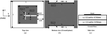
A rectangular patch of dimensions 4.13 cm × 4.85 cm is designed using stacking of two Rogers Duroid 5880 (ε r1 = ε r2 = 2.2 and h 1 = h 2 = 0.762 mm) substrate sheets of dimensions 7 cm × 7 cm. The top-view, bottom-view, and side-view of the designed antenna are shown in Figs 1(a)–1(c), respectively. For exciting the patch, a 50 Ω-microstrip feed line is used. For improving the performance parameters of this patch antenna, two asymmetrical-slots (viz. slot-1 and slot-2) on radiating surface as well as two symmetrical-slots (viz. slot-3 and slot-4) in ground plane, are inserted. These slots are shown in Figs 1(a) and 1(b), respectively. In Fig. 1, P, Q, R, and S are the center positions of respective slots. All dimensions in Figs 1(a) and 1(b) are in cm.
Antenna geometry for illustrative example. (a) Top-view, (b) bottom-view (ground plane), (c) side-view.

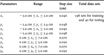
The dimensions of slot-1 and slot-2 are optimized first. The performance parameters of the proposed antenna are then analyzed using HFSS simulator [32] for different values of slots-positions such as P(x 1, y 1) and Q(x 2, y 2), respectively. The positions of slot-3 and slot-4 are optimized as: R(x = 0 cm, y = 3.25 cm) and S(x = 0 cm, y = −3.25 cm), respectively. Performance parameters of the proposed antenna are also analyzed for different values of slots-sizes like: (x 3, y 3) and (x 4, y 4), correspondingly. Here (x 3, y 3) and (x 4, y 4) corresponds to the slot-size of slot-3 and slot-4, respectively. Total 198 sets of training pattern and another 40 sets of testing pattern are generated using the HFSS simulator. During simulation process, the sampling strategy shown in Table 1, is used.
Sampling strategy.

III. SVM AND PREDICTION
In this section, few generalized mathematical steps of using SVR machine are being described for calculating the resonant frequency (f), gain (G), directivity (D), and radiation efficiency (R), respectively:
Consider x
i
be the input vector and y
i
is a desired value and then the training data set is mentioned as:
 $\{ (x_i, \; y_i )\} _i^P $
where P is the total number of data patterns. Now the task of using SVR is to find out the approximation function f(x) as:
 $$f(x) = [w,\;\delta (x)] + B.$$
In (1), δ(x) is a non-linear mapping vector, which maps the input variable x into a high-dimensional new space where bias and weighting vector are denoted by B and w, respectively, and inner product is denoted by [….].
The non-linear machine is then build-up by taking non-linear mapping vector transforming data into a feature space and then linear machine constructed in high-dimensional space to perform regression on data. From minimization of regression risk function, the weighting vectors and biases can be found [Reference Neog, Pattnaik, Panda, Devi, Khuntia and Dutta8] as follows:
 $$R_{reg} = C\mathop \sum \limits_{i = 0}^{P - 1} L^\varepsilon (x,\;y,\;f) + \displaystyle{1 \over 2}w^2. $$
In (2), C denotes the regularization parameter, which determines the tradeoff between the empirical loss function. The model complexity, L ε(x, y) represents the ε-insensitive loss function and (1/2)w 2 stands for characterization of the modeling complexity. This regression risk function provides SVR global minimum or global unique solution, which gives it more priority than ANN because ANN has multiple local minima problem. Here one of the familiar loss functions, ε-insensitive loss function is employed, which is developed by Vapnik [Reference Neog, Pattnaik, Panda, Devi, Khuntia and Dutta8]:
 $$L^\varepsilon (x,\;y,\;f) = \left\{ {\matrix{ {0,} & {{\rm if}\; \vert y^i - f(x)^i \vert \le \varepsilon,} \cr { \vert y^i - f(x)^i \vert - \varepsilon,} & {{\rm else}{\rm.}} \cr}} \right.$$
The vector can be represented in terms of input data x according to [Reference Neog, Pattnaik, Panda, Devi, Khuntia and Dutta8]:
 $$w = \mathop \sum \limits_{i = 0}^{P - 1} (\alpha _i - \alpha _i^* )\delta (x^i )$$
 $$f(x) = \mathop \sum \limits_{i = 0}^{P - 1} (\alpha _i - \alpha _i^* ) \lt \delta (x^i ),\;\delta (x) \gt + B = \mathop \sum \limits_{i = 0}^{P - 1} (\alpha _i - \alpha _i^* )K(x^i, x) + B.$$
Here α
i
and
 $\alpha _i^* $
are the positive Lagrangian multipliers obtained by minimization of regression risk in dual space objective function. Kernel function K(x
i
, x) in (5) works on original space. The widely used kernel functions are polynomial and radial basis kernel function. Lagrangian multipliers obtained by maximization of the following dual space objective function [Reference Lebbar, Guennoun, Drissi and Riouch9]:
 $$W(\alpha, \alpha ^* ) = - \varepsilon \mathop \sum \limits_{i = 0}^{P - 1} (\alpha _i^* + \alpha _i ) + \mathop \sum \limits_{i = 0}^{P - 1} G^i (\alpha _i^* - \alpha _i ) - \displaystyle{1 \over 2}\mathop \sum \limits_{i = 0}^{P - 1} (\alpha _i^* - \alpha _i )(\alpha _i^* + \alpha _i )K(x^i, \;x),$$
with the constraints:
 $$0 \le \alpha _i^*, \;\alpha _i \le C,$$
 $$\mathop \sum \limits_{i = 0}^{P - 1} (\alpha _i^* - \alpha _i ) = 0.$$
From Karush–Kuhn–Tucker conditions [Reference Neog, Pattnaik, Panda, Devi, Khuntia and Dutta8], the variables
 $\alpha _i, \;\alpha _i^*, \;{\rm and}\;B$
can be estimated using constraints given in (7a) and (7b). This condition also supports (3) which imply that the Lagrange multipliers can be non-zero for |y
i
− f(x)
i
| ≥ ε otherwise zero, i.e. thus, the Lagrangian multipliers
 $\alpha _i, \;\alpha _i^* $
vanish. There is no need of all data points for describing w because in terms of x, a sparse expansion w is there. The SVs are those non-vanishing coefficients from the samples (x
i
, yi
). These small subsets of training points reduce the number of parameters with global minimum gains superiority to SVM over the alternative methods [Reference Neog, Pattnaik, Panda, Devi, Khuntia and Dutta8, Reference Guney and Sarikaya10]. Further, the widely used kernel function, radial basis function (RBF) is expressed as:
 $$K(x^i, x) = {\rm exp}( - \gamma x - x^{i2} ).$$
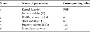
The proposed SVM modeling is optimized with the initial parameters mentioned in Table 2.
SVM parameters.

The process for computing the desired value, y and total P number of data pairs in the form:
 $\{ (x_i, \; y_i )\} _i^P $
is described using SVM in (1)–(8). The analysis described in (1)–(8) can be used for computing the resonant frequency (f), gain (G), directivity (D), and radiation efficiency (R), respectively. The training and testing patterns for the above described SVM modeling can be created using these equations or can also be generated via simulation work. For the proposed work, the training and testing patterns are generated via HFSS simulation which has already been described in Section II.
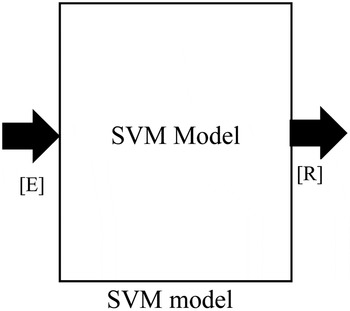
The SVR machine described in this section is used for modeling of slotted microstrip antennas with modified ground plane. For further illustration, the process is summarized in a block diagram shown in Fig. 2 where the input and output to the SVM model are described as matrix_[E]→[x 1 y 1 x 2 y 2 x 3 y 3 x 4 y 4] and matrix_[R]→ [f G D R], respectively. Here (x 1, y 1) and (x 2, y 2) represent the position of asymmetrical slot-1 and slot-2, respectively, whereas (x 3, y 3) and (x 4, y 4) represent the size of symmetrical slot-3 and slot-4, respectively. In the response matrix_[R], the variable f, G, D, and R represent the resonant frequency, gain, directivity and radiation efficiency, respectively. These variables have already been discussed in Section II.
SVM model.

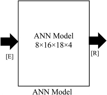
For better understanding of the SVM prediction, a conventional MLP (multilayered perceptron) ANN model of structural configuration 8 × 16 ×18 ×4. The proposed ANN approach is created using the approach as described in the literature [Reference Khan, De and Uddin3–Reference Wang, Fang, Wang and Liu12]. The prediction of resonant frequency (f), gain (G), directivity (D) and radiation efficiency (R) is summarized using block diagram in Fig. 3. The excitation and response for the ANN model is similar to the excitation and response of SVM model shown in Fig. 2.
ANN Model.

IV. COMPUTED RESULTS AND VALIDATION
A) Numerical results
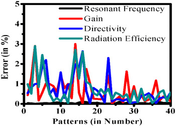
In Section II, the process of generating 198 training patterns and 40 testing patterns is carried out with the help of ANSYS HFSS code package. The SVM modeling followed by conventional ANN modeling for these simulated patterns is then described in Section III. The computed results are then compared with their simulated counterparts for both SVM and ANN and this comparison is summarized in Table 3. Thus, it is concluded that the SVM model is more accurate than ANN model. Further, the computed error during testing of SVM model is also plotted in Fig. 4. Thus, it is concluded that the computed points are found in a very good agreement to their simulated counterparts and only few points are observed far off in the entire process. In addition, the simulation time in both SVM and ANN procedures is also summarized in Table 4 for resonant frequency (f) only. Eventually, it is evident that SVM is more time efficient as compared to ANN although both techniques provided similar accuracies during computation.
Error comparison.

Accuracies comparison.

Training and testing time analysis.

B) Experimental results
For validating the proposed work, an antenna prototype is fabricated using stacking of two Rogers Duroid 5880 (ε r1 = ε r2 = 2.2 and h 1 = h 2 = 0.762 mm) substrate sheets of dimensions 7 cm × 7 cm. The dimensions of slot-1 and slot-2 are optimized as: 0.1 cm × 2.0 cm and 2.6 cm × 0.25 cm, respectively and these slots are placed at their optimized positions, i.e. P(x = −0.3 cm, y = −0.7832 cm) and Q(x = 0.68 cm, y = −0.6982 cm), simultaneously. The dimensions of slot-3 and slot-4 are optimized as: 5.5 cm × 0.5 cm and 5.5 cm × 0.5 cm, respectively and these slots are placed at their optimized positions, i.e. R(x = 0 cm, y = 3.25 cm) and S(x = 0 cm, y = −3.25 cm) concurrently. The designed antenna is excited by a 50 Ω-microstrip feed line. For each simulation, the antenna performance is observed between 1.75 and 2.50 GHz.
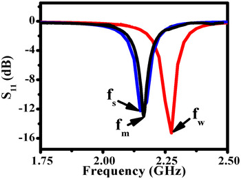
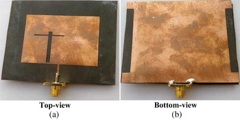
Figure 5 illustrates the comparison of S 11-values for reference patch antenna without any slot on the radiating surface with their simulated as well as measured values of slotted optimized antenna geometry. The S 11-parameters of the fabricated prototype are measured using an Agilent N5230A network analyzer. The snapshots of the fabricated antenna are shown in Fig. 6.
S-Parameters comparison.

Snapshots of fabricated antenna. (a) Top-view, (b) bottom-view.

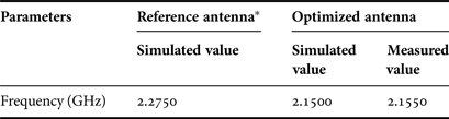
A comparison between simulated and predicted resonant frequency is also summarized in Table 5. The simulated resonant frequency of referenced antenna (i.e. an antenna without any slot) is observed as: f w = 2.2750 GHz, simulated frequency of optimized antenna is observed as: f s = 2.1500 GHz, whereas the measured resonant frequency with optimized antenna is observed as: f m = 2.1550 GHz. Thus, a very good conformity is achieved if the simulated resonant frequency (i.e. 2.1500 GHz) is compared with its corresponding measured values (i.e. 2.1550 GHz).
Resonant frequency comparison.

* An antenna without any slot.
Without inserting the slots on the radiating surface, the simulated resonant frequency is observed as 2.2750 GHz but after inserting the slots, the resonant frequency is reduced to 2.1500 GHz (simulated value). By introducing the slots, the excited surface current path lengthens, increases the antenna length and hence decreases the resonant frequency. For the designed prototype, the resonant frequency (i.e. 2.1500 GHz) is lowered by 5.49% as compared with that (i.e. 2.2750 GHz) of the antenna geometry without slots, which can result to a patch size reduction of 19.78% for a given resonant frequency design. Hence, a good rank of compactness is achieved in the optimized prototype.
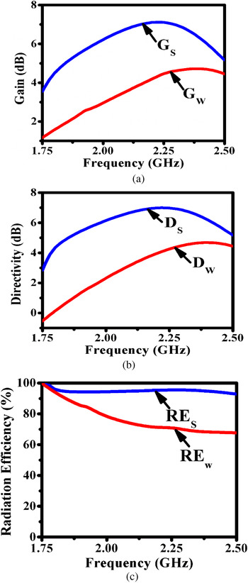
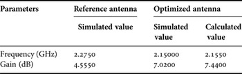
Figure 7(a) illustrates the comparison of simulated gain values for reference antenna and optimized antenna. A fair improvement in gain is achieved by inserting the slots on radiating patch as well as in the ground plane. The gain values for both the cases are also compared in Table 6 with the corresponding calculated value. Figure 7(a) depicts the gain associated with resonant frequency, which is found around 4.5550 dB and 7.0200 dB corresponding to the reference antenna and optimized simulated antenna, respectively.
Performance parameters comparison. (a) Gain comparison, (b) directivity comparison, (c) efficiency comparison.

Simulated and measured gain comparison.

* An antenna without any slot.
The gain given in the last column of Table 6 is the calculated value and this is calculated using the Friis Transmission equation mentioned in (9).
 $$P_R = \displaystyle{{{P_T} {G_T} {G_r} \lambda ^2} \over {(4\pi R)^2}}. $$
From the used experimental setup, P T = Cable loss = −8.5 dBm, P R = maximum power received at 0° = −36.56 dBm, and R = distance between testing antenna and horn antenna = 200 cm.
Now calculating,
 $$\lambda = \displaystyle{c \over f} = 13.92\;{\rm cm,}$$
 $$\eqalign{K &= \left( {\displaystyle{\lambda \over {4\pi R}}} \right)^2 \cr &= \left( {\displaystyle{{13.92} \over {4 \times 3.14 \times 200}}} \right)^2 = - {\rm 45}\;{\rm dB}\;[{\rm 1}0{\rm log}_{{\rm 1}0} {\rm K}].}$$
Substituting these values into (9),
 $$G_r = {\rm 7}.{\rm 44}\;{\rm dB}{\rm.} $$
The directivity and radiation efficiency for both reference antenna and optimized antenna are also compared in Figs 7(b) and 7(c), respectively. The values of directivity and radiation efficiency at respective resonant frequency are summarized in Table 7. Hence, a very good improvement is attained in the optimized antenna as compared with that of the reference antenna. The difference between the measured and simulated values might be due to error in fabricating the antenna especially during staking of two substrates. Further, the simulation does not include the effect of connector as well as the amount of solder wire used to connect the PCB board to the connector.
Parameters comparison (simulated values).

* An antenna without any slot.
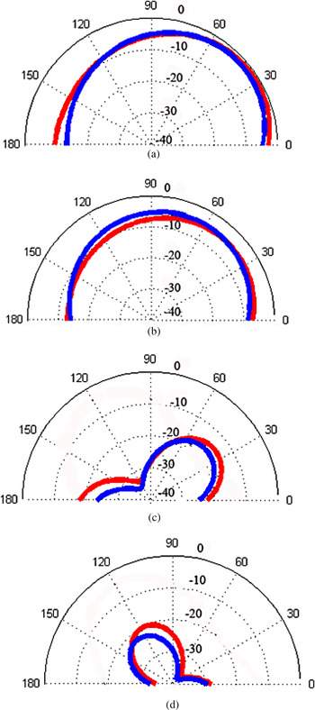
The two-dimensional (2D) radiation patterns of the optimized antenna are shown in Fig. 8 and it shows that the differences between co-and cross-polarization in both the planes are above 20 dB. Hence, the overall patterns for both H- and E-planes are providing good polarization purity.
Radiation patterns comparison Blue Color for simulated and Red Color for Measured. (a) H-plane patterns (co-pol), (b) E-plane patterns (co-pol), (c) H-plane patterns (x-pol), (d) E-plane patterns (x-pol).

V. CONCLUSION
In this communication, the SVM-based modeling has been proposed for computing four different performance parameters for the given eight different input parameters of a rectangular microstrip antenna accurately. In addition, one conventional ANN model has also been optimized and compare the performance of this ANN model with that of the SVM model. The computed results via SVM and ANN models have been compared and the SVM model has been proved more accurate as well as faster than that of ANN model.
By using a RBF-kernel algorithm, authors have established a more effective and accurate analysis model for microstrip antennas. The approach has produced more accurate results, hence it can also be recommended to include in antenna computer-aided design (CAD) algorithms. In general, computation of four different parameters may require four different neural networks modules/SVM models, whereas in the present work, only one module is fulfilling the requirement of four independent modules.
For validation purpose, a prototype has also been fabricated and characterized. A very good convergence between measured and simulated results has been achieved over the entire operating band, which supports the effectiveness of the proposed work. A good amount of improvement in the performance parameters especially in antenna gain has also been observed by inserting two asymmetrical slots on the radiating surface as well as two symmetrical slots in the ground plane. Hence, an encouraging amount in four different performance parameters, i.e. resonant frequency, gain, directivity and radiation efficiency has been found which makes it a better candidate for improved radiation characteristics applications in wireless communications.
 Chandan Roy has obtained his M.Tech. degree in Communication and Signal Processing Engineering specialization in 2016 from National Institute of Technology (An Institute of National Importance, Ministry of HRD, Govt. of India), Silchar, India under Bangladesh Scholarship Scheme, 2014–2016. Prior to that, he has obtained his B.Sc. degree in Electrical and Electronic Engineering from Khulna University of Engineering and Technology, Bangladesh in 2013. Presently, he is working toward getting enrolled in Ph.D. program. His current research interests include Antenna Design, Computational Electromagnetics, Machine Learning, and Signal Processing.
 Dr. Taimoor Khan is an Assistant Professor in the Department of Electronics and Communication Engineering at National Institute of Technology (An Institute of National Importance, under Ministry of Human Resource Development, Government of India) Silchar, India, where he serves as a full-time faculty member from 2014. Presently, he is working as a Visiting Assistant Professor in Telecommunication Field of Study at Asian Institute of Technology, Bangkok, Thailand under Secondment Program of Ministry of HRD, Govt. of India for the duration of September–December, 2016. Prior to joining National Institute of Technology Silchar, he served several organizations such as Delhi Technological University (Formerly Delhi College of Engineering), Govt. of NCT of Delhi, Delhi, India for more than 2 years; Netaji Subhas Institute of Technology Patna, India for more than 1 year and Shobhit Institute of Engineering and Technology (a Deemed University), Meerut, India for more than 9 years. Dr. Khan had awarded his Ph.D. degree in Electronics and Communication Engineering from National Institute of Technology (An Institute of National Importance, under Ministry of Human Resource Development, Govt. of India) Patna, India in the year 2014. He obtained his Master's degree in Communication Engineering from Shobhit Institute of Engineering and Technology (a Deemed University), Meerut, India (2009); Bachelor degree in Electronics and Communication Engineering from The Institution of Engineers (India), Kolkata, India (2005), and Polytechnic diploma in Electronics Engineering from Government Polytechnic Saharanpur, India (2001). His active research interest includes Communication Engineering, Printed Microwave and Millimeter Wave Circuits, Electromagnetic Bandgap Structures, Computational Electromagnetics, and Artificial Intelligence Paradigms in Communication Engineering. He has published over 28 research papers in international journals, including IEEE, Wiley, PIER, etc. as well as in international/national conference proceedings, including AEMC, APACE, ISMOT, etc. In addition, he has successfully organized several academic events such as Workshop, Faculty Development Program, Expert Lecture Series, etc. as well as attended several international/national conferences of repute. He is an active member of IEEE (USA), life member of IEI (India), and life member of IAE (Hong Kong).
 Dr. Binod Kumar Kanaujia has been working as a Professor in the School of Computational and Integrative Sciences, Jawaharlal Nehru University, New Delhi since August, 2016. Before joining Jawaharlal Nehru University, he had been in the Department of Electronics & Communication Engineering in Ambedkar Institute of Advanced Communication Technologies & Research (formerly Ambedkar Institute of Technology), Delhi as a Professor since February 2011 & Associate Professor (2008–2011) and Dr. Kanaujia held the positions of Lecturer (1996–2005) and Reader (2005–2008) in the Department of Electronics & Communication Engineering, and also as Head of the Department in the M.J.P. Rohilkhand University, Bareilly, India. Prior to his career in academics, Dr. Kanaujia had worked as an Executive Engineer in the R&D division of M/s UPTRON India Ltd. Dr. Kanaujia had completed his B.Tech. in Electronics Engineering from KNIT Sultanpur, India in 1994. He did his M.Tech. and Ph.D. in 1998 and 2004; respectively from Department of Electronics Engineering, Indian Institute of Technology Banaras Hindu University, Varanasi, India. He has been awarded Junior Research Fellowship by UGC Delhi in the year 2001–2002 for his outstanding work in electronics field. He has keen research interest in design and modeling of microstrip antenna, dielectric resonator antenna, left-handed metamaterial microstrip antenna, shorted microstrip antenna, ultra wideband antennas, reconfigurable, and circular polarized antenna for wireless communication. He has been credited to publish more than 150 research papers with more than 430 citations with h-index of 12 in peer-reviewed journals and conferences. He had supervised 50 M.Tech. and eight Ph.D. research scholars in the field of microwave engineering. He is a reviewer of several journals of international repute, i.e. IET Microwaves, Antennas & Propagation, IEEE Antennas and Wireless Propagation Letters, Wireless Personal Communications, Journal of Electromagnetic Wave and Application, Indian Journal of Radio and Space Physics, IETE Technical Review, International Journal of Electronics, International Journal of Engineering Science, IEEE Transactions on Antennas and Propagation, AEU-International Journal of Electronics and Communication, International Journal of Microwave and Wireless Technologies, etc. Dr. Kanaujia had successfully executed four research projects sponsored by several agencies of Government of India, i.e. DRDO, DST, AICTE, and ISRO. He is also a member of several academic and professional bodies, i.e. IEEE, Institution of Engineers (India), Indian Society for Technical Education, and The Institute of Electronics and Telecommunication Engineers of India.