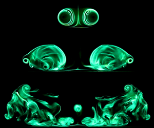


1. Introduction
Vortex rings have always fascinated fluid dynamists at large, due to their structural simplicity and relevance towards much more complex flow scenarios that in turn lend themselves towards engineering flow applications such as synthetic jets for flow control purposes (Amitay et al. Reference Amitay, Smith, Kibens, Parekh and Glezer2001; Gilarranz, Traub & Rediniotis Reference Gilarranz, Traub and Rediniotis2005; You & Moin Reference You and Moin2008), impinging jets for heat transfer applications (Martin Reference Martin1977; Goldstein & Franchett Reference Goldstein and Franchett1988; Hadžiabdić & Hanjalić Reference Hadžiabdić and Hanjalić2008; New & Long Reference New and Long2015), vortex-ring state in helicopter flights (Newman et al. Reference Newman, Brown, Perry, Lewis, Orchard and Modha2001; Leishman, Bhagwat & Ananthan Reference Leishman, Bhagwat and Ananthan2004; Johnson Reference Johnson2005) and, more recently, particle-shaping techniques (An et al. Reference An, Warning, Yancey, Chang, Kern, Datta, Steen, Luo and Ma2016; Zhan et al. Reference Zhan, Yan, Li, Meng, Wang, Zhang, Yu and Xia2017), among others. It should come as no surprise then, that significant research has been expended to expand our fundamental understanding of vortex rings and how they interact with their surroundings. Take, for instance, more recent studies on the behaviour of translating discrete circular vortex rings that would include Maxworthy (Reference Maxworthy1972), Didden (Reference Didden1979), Pullin (Reference Pullin1979), Glezer (Reference Glezer1988), Glezer & Coles (Reference Glezer and Coles1990), Nitsche & Krasny (Reference Nitsche and Krasny1994), Heeg & Riley (Reference Heeg and Riley1997), Gharib, Rambod & Shariff (Reference Gharib, Rambod and Shariff1998), Mohseni & Gharib (Reference Mohseni and Gharib1998), Mohseni, Ran& Colonius (Reference Mohseni, Ran and Colonius2001), Krueger, Paul & Gharib (Reference Krueger, Paul and Gharib2003), Krueger, Dabiri & Gharib (Reference Krueger, Dabiri and Gharib2006), Shusser et al. (Reference Shusser, Rosenfeld, Dabiri and Gharib2006), Feng, Kaganovskiy & Krasny (Reference Feng, Kaganovskiy and Krasny2009), Kaplanski et al. (Reference Kaplanski, Sazhin, Fukumoto, Steven and Heikal2009), Gao & Yu (Reference Gao and Yu2010), Gan, Dawson & Nickels (Reference Gan, Dawson and Nickels2012), Ponitz, Sastuba & Brücker (Reference Ponitz, Sastuba and Brücker2016) and Mao & Hussain (Reference Mao and Hussain2017), among many others. These investigations primarily focused upon how initial and boundary conditions affect vortex-ring generation, nature of laminar and turbulent vortex-ring formation and propagation, vortex-ring formation time scales, azimuthal wave instabilities, relationships between the initial vortex rings in starting jets, and other important characteristics.
Many experimental and numerical studies have also been conducted for vortex-ring collision scenarios. Such scenarios will be of special interest, as they entail the direct impact and subsequent interactions between two vortex rings or a vortex ring and solid/non-solid boundaries, as opposed to a discrete vortex-ring entity assumed to be free (or largely free) of external influences. Such scenarios have been studied systematically earlier, including but not limited to those reported by Walker et al. (Reference Walker, Smith, Cerra and Doligalski1987), Lim (Reference Lim1989), Lim, Nickels & Chong (Reference Lim, Nickels and Chong1991), Orlandi & Verzicco (Reference Orlandi and Verzicco1993), Verzicco & Orlandi (Reference Verzicco and Orlandi1994), Chu, Wang & Chang (Reference Chu, Wang and Chang1995), Swearingen, Crouch & Handler (Reference Swearingen, Crouch and Handler1995), Fabris, Liepmann & Marcus (Reference Fabris, Liepmann and Marcus1996), Minota, Nishida & Lee (Reference Minota, Nishida and Lee1997), Naitoh, Banno & Yamada (Reference Naitoh, Banno and Yamada2001), Arévalo et al. (Reference Arévalo, Hernández, Nicot and Plaza2007), Cheng, Lou & Luo (Reference Cheng, Lou and Luo2010), Couch & Krueger (Reference Couch and Krueger2011), Mariani et al. (Reference Mariani, Quinn, Kontis and Marraffa2013), New, Shi & Zang (Reference New, Shi and Zang2016) and Xu & Wang (Reference Xu and Wang2016) for flat/inclined-walls, Adhikari & Lim (Reference Adhikari and Lim2009), Hrynuk, Van Luipen & Bohl (Reference Hrynuk, Van Luipen and Bohl2012), Naaktgeboren, Krueger & Lage (Reference Naaktgeboren, Krueger and Lage2012), Cheng, Lou & Lim (Reference Cheng, Lou and Lim2014) and Xu et al. (Reference Xu, Wang, Feng, He and Wang2018) for porous walls, Orlandi (Reference Orlandi1993), Naitoh, Sun & Yamada (Reference Naitoh, Sun and Yamada1995), Ren, Zhang & Guan (Reference Ren, Zhang and Guan2015) and New & Zang (Reference New and Zang2017) for round cylinders, and, more recently, a scenario whereby a vortex ring collides upon a wall with a circular aperture investigated by Hu & Peterson (Reference Hu and Peterson2018).
Recently, New et al. (Reference New, Zang, Shi and Long2018) conducted a limited study to explore  ${Re} =1000$ vortex rings impacting upon V-walls, a configuration that can essentially be treated as two single inclined walls arranged and joined at the apex symmetrically. While many vortex-ring collisions had been based on flat/inclined walls, V-wall configurations have not been systematically explored before. There are several interesting key differences between the use of V-walls and other wall types for vortex-ring collisions that ought to be highlighted. Firstly, when compared to an inclined wall, a V-wall poses a far more physically constrained boundary condition where the vortex-ring motion will be physically limited by the valley downstream of the collision axis. As such, more extensive vortical motions along the orthogonal plane of the V-wall will be expected. Secondly, two vortex-ring segments will collide with both V-wall surfaces simultaneously and symmetrically, as opposed to one colliding after another for an inclined wall. As such, the overall three-dimensional flow dynamics are expected to deviate from, but continue to be inspired by, the bi-helical line flow model first put forward by Lim (Reference Lim1989) and confirmed by Verzicco & Orlandi (Reference Verzicco and Orlandi1994) and New et al. (Reference New, Shi and Zang2016) for inclined-wall collisions. Furthermore, in contrast to vortex-ring collisions upon more convex surfaces such as round cylinders, V-wall collisions will provide some key insights into the resulting flow structures and behaviour when more concave-like wall types are used instead, even if curvature effects are not accounted for.
The present study follows up and expands upon the earlier study by experimentally investigating  ${Re} =2000$ and 4000 vortex-ring collisions upon V-walls with included angles ranging from 30
 $^{\circ }$ to 120
 $^{\circ }$ at 30
 $^{\circ }$ intervals. In particular, the use of additional higher Reynolds numbers and V-walls here is expected to shed more light upon the effects of various parameters. The present objectives are to provide more definitive information along several research fronts. Firstly, how different are V-wall collisions from single inclined-wall collisions and how can well-established flow dynamics associated with the latter be tapped to explain the former's behaviour? Secondly, to what extent do vortex-ring Reynolds number and included angle influence the resulting collision behaviour, circulation levels and vortex-core trajectories? Last but not least, how do the key flow mechanisms underpinning the present experimental observations compare to earlier findings on inclined-wall or round-cylinder-based collisions?
To address these questions, laser-induced fluorescence (LIF) visualizations and time-resolved particle image velocimetry (TR-PIV) measurements were utilized to reveal more details. Similar experimental approaches have already been used by the authors previously in unravelling pertinent details on inclined-wall and round-cylinder-based vortex-ring collisions (New et al. Reference New, Shi and Zang2016; New & Zang Reference New and Zang2017). From the perspectives of engineering applications, the experimental evidence will also provide more flow insights into how continuous or synthetic impinging jet flow behaviour (of which vortex rings can be treated as their most fundamental flow entity) could be further improved in terms of providing more uniform and efficient heat transfer functions for non-uniform surface geometries.
2. Experimental set-up
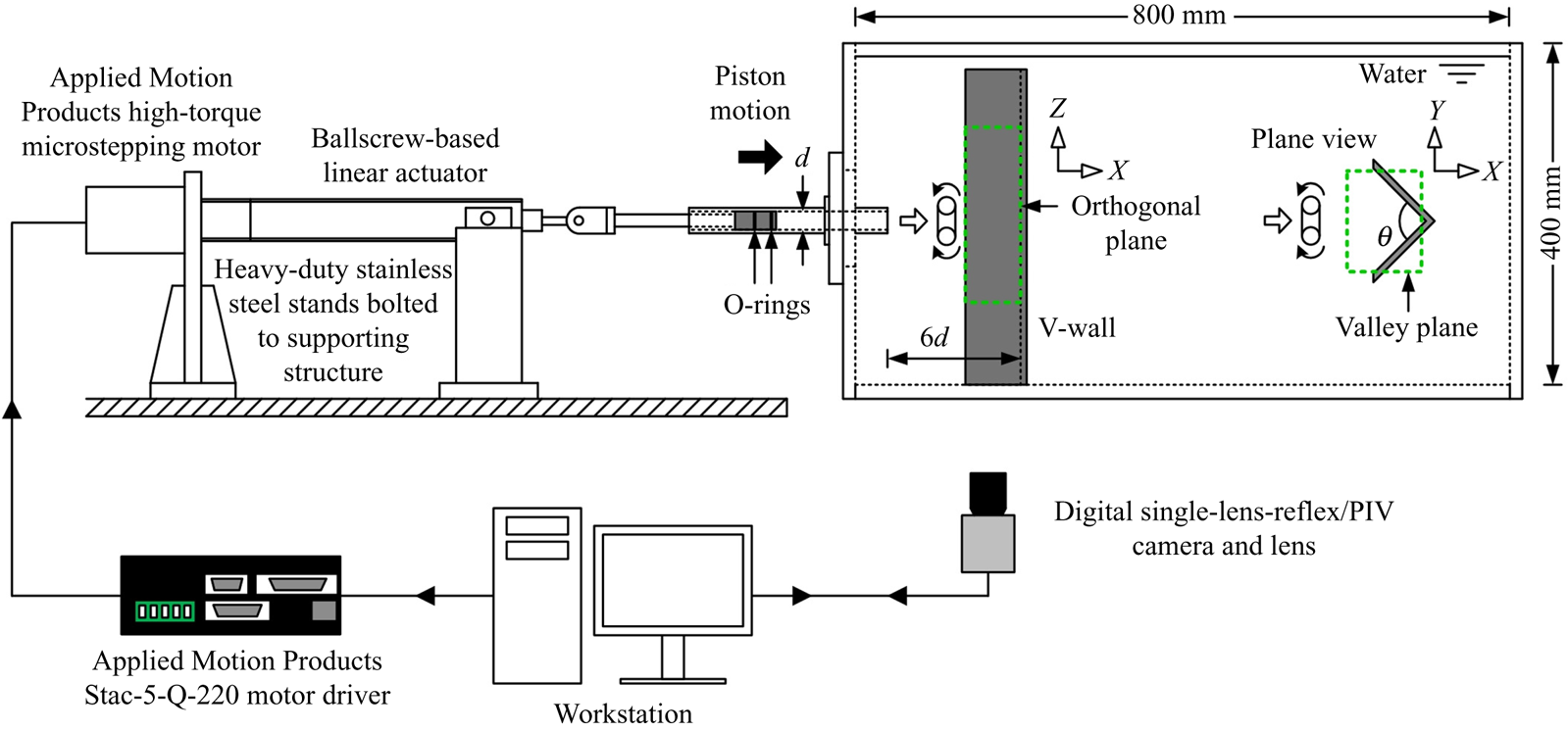
All experiments were conducted in the same water-tank-based experimental set-up as described in New et al. (Reference New, Shi and Zang2016) and New & Zang (Reference New and Zang2017), and hence only a brief description will be provided here. With reference to figure 1, discrete circular vortex rings were generated via sudden impulses from a piston to push water out of a nozzle. The piston was located within a stainless-steel round tube with an internal diameter of 20 mm, the latter of which was attached to a circular Plexiglas attachment with a similarly sized hole. A cylindrical dye port was designed within the circular attachment such that fluorescent dye could be released uniformly into the working fluid through a 1 mm wide built-in circumferential slit by a gravity-fed dye release system. Lastly, a  $d=20$ mm inner-diameter circular nozzle was fixed to the circular attachment, where a ‘cylindrical slug’ of water exited from it and into the quiescent water. Depending on the viewing requirements of the experiments, thin 0.09 mm matt black adhesive paper was applied on either one or both of the V-wall inner surfaces to minimize laser reflections during the experiments.
Schematics of the piston-based, ‘cylindrical-slug’ vortex-ring generator and experimental apparatus, which are very similar to those used by New et al. (Reference New, Shi and Zang2016) and New& Zang (Reference New and Zang2017).

The vortex-ring Reynolds numbers investigated here are approximately  ${Re} =Ud/\nu =2000$ and 4000 (where
 $U$ and
 $\nu$ are the piston mean velocity and kinematic viscosity of water at working conditions, respectively), which correspond to
 ${Re} _{\Gamma }=\Gamma /\nu =2500$ and 5000, respectively, indicating that the vortex rings are generally laminar. All vortex rings were produced with the stroke length held at
 $L=30$ mm throughout the study, resulting in a constant stroke ratio of
 $L/d=1.5$. This stroke ratio is significantly smaller than the critical
 $L/d=3.6$, above which trailing jets would be produced behind the vortex rings (Gharib et al. Reference Gharib, Rambod and Shariff1998). Circulations estimated from TR-PIV measurements for the
 ${Re} =2000$ and 4000 vortex rings here are approximately
 $\Gamma =0.0025$ and
 $0.050~\textrm {m}^2~\textrm {s}^{-1}$, respectively. These values compare well with those in the studies by Weigand & Gharib (Reference Weigand and Gharib1997) and Couch & Krueger (Reference Couch and Krueger2011). For instance, the circulation of the
 ${Re} =1650$,
 $L/d=0.87$, vortex ring in Weigand & Gharib (Reference Weigand and Gharib1997) was estimated to be approximately
 $0.00162~\textrm {m}^2~\textrm {s}^{-1}$. Additionally, normalized circulations for
 ${Re} =2000$,
 $L/d=0.75$, vortex rings in Couch & Krueger (Reference Couch and Krueger2011) are approximately
 $\Gamma /(dU_{max})=0.8$ at approximately 2–3 diameters above the collision surface. This is compared to a normalized circulation value of approximately
 $\Gamma /(dU_{\textit{max}})=0.96$ here. Considering the significantly larger stroke ratio used in the present study as compared with these earlier studies, the circulations of the present vortex rings are comparable with those in these earlier studies. Additionally, the vortex-ring aspect ratios are estimated to be
 $d_0/\sigma =2.10$ and 2.95 at
 ${Re} =2000$ and 4000, respectively, where
 $d_0$ is the vortex-ring core-to-core diameter and
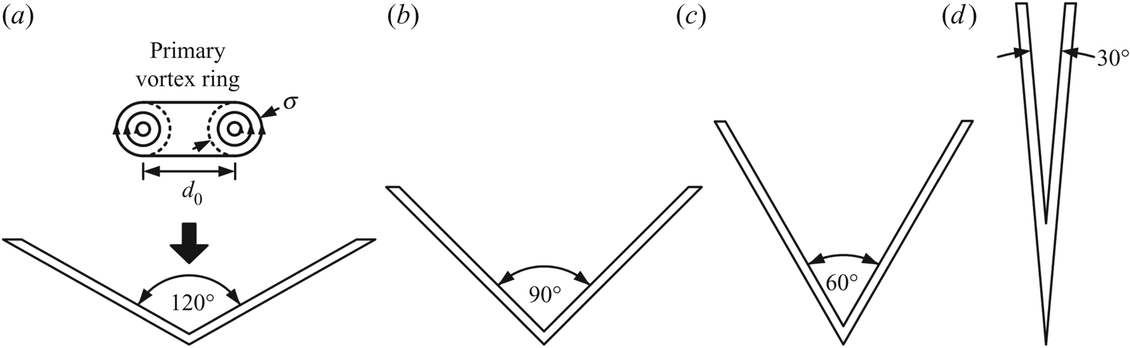
 $\sigma$ is the vortex-ring core diameter as shown in figure 2(a). Last but not least, vortex-ring profiles are compared to those approximated using Gaussian functions (Orlandi Reference Orlandi1993; Cheng et al. Reference Cheng, Lou and Luo2010) and observed to be Gaussian-like. There is good agreement in the peak velocities, though velocity decays are observed to be faster in the experimental results compared to an idealized Gaussian distribution.
Four V-wall configurations used in the present vortex-ring collision study, where the included angle,  $\theta$, ranged from 120
 $^{\circ }$ to 30
 $^{\circ }$ at 30
 $^{\circ }$ intervals.

The LIF visualization and TR-PIV measurement procedures were similar to those in the authors’ earlier studies. For two-dimensional LIF visualization, fluorescein disodium dye was premixed with water and a small amount was released upstream of the circular nozzle just prior to each experiment. A 532 nm continuous-wave diode-pumped solid-state (DPSS) laser was used to produce an approximately 1.5 mm thick laser sheet with the use of beam-steering mirrors and sheet-forming optics. The laser sheet was positioned horizontally with respect to the set-up during the flow visualization experiments and the V-walls oriented vertically or horizontally to allow visualizations along the ‘valley plane’ or ‘orthogonal plane’, as shown in figure 1 as planes highlighted by green dashed lines. Based on the present coordinate system, the valley and orthogonal planes are aligned with the  $XY$ and
 $XZ$ planes, respectively. A remote-controlled
 $1920 \times 1080$ pixels digital single-lens-reflex camera with a 50 mm,
 $f1.4$ lens was then used to capture the visualized flow behaviour through 30 f.p.s. (frames per second) video recordings. As the results will show later, the present vortex-ring collision scenarios would lead to significantly different flow developmental time spans along the valley and orthogonal planes when the Reynolds number and/or included angle vary. Hence, to better highlight the key vortex structures and behaviour associated with each particular configuration, visualization images taken at different timings will be presented instead of presenting them at the same timings regardless of the exact configuration.
For TR-PIV experiments, the same DPSS laser was used but with an IDT greyscale high-speed camera capable of up to 1000 f.p.s. instead. The high-speed camera has a resolution of  $1024 \times 1024$ pixels and was set to capture sequential particle images at 250 to 350 f.p.s., depending on the vortex-ring Reynolds number. It should be noted that the camera captured particle images associated with half of the symmetrical flow fields along the orthogonal plane, as the flow developments occurred over significantly larger distances along this plane. In contrast, a smaller measurement window was used along the valley plane, since the flow structures and developments were constrained within smaller regions by the physical boundaries of the V-walls. All time-series particle images were post-processed based on similar procedures adopted by New et al. (Reference New, Shi and Zang2016) and New & Zang (Reference New and Zang2017), and readers are advised to refer to those papers for more procedural details and uncertainty levels. Last but not least, it should be noted that, since the LIF visualizations and TR-PIV measurements were captured at different frame rates and hence temporal resolutions, the results presented here were selected such that their timings for the same configuration and instant are as close to each other as possible.
3. Results and discussion
3.1. Vortical developments along valley plane
Before the results for the present study are presented, it will be worthwhile first to briefly recall the flow dynamics associated with laminar vortex rings colliding normally with a flat wall. As observed in an earlier study (New et al. Reference New, Shi and Zang2016), a  ${Re} =2000$ primary vortex ring flattens with an increase in the vortex-ring diameter shortly after it collides with the wall. Subsequently, under the effects of an adverse pressure gradient, the increasingly larger primary vortex ring leads to the first wall boundary layer separation that produces a secondary vortex ring with an opposite rotational sense. Thereafter, the secondary vortex ring leapfrogs over and gets entrained within the inner confines of the primary vortex ring. At around the same time, the primary vortex ring produces a second wall boundary layer separation and hence a tertiary vortex ring. Similar to the secondary vortex ring, the tertiary vortex ring may subsequently get entrained by the primary vortex ring, depending on the primary vortex-ring configuration.
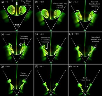
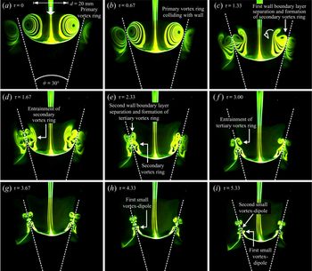
Figures 3 to 6 show instantaneous time-sequenced LIF visualizations for a  ${Re} =2000$ vortex ring colliding with the four different V-walls, which were taken with the camera facing the
 $XY$ plane (i.e. valley plane). Note that flow images at short time intervals are presented here for a first-hand qualitative appreciation of the underlying flow dynamics. Non-dimensionalized timings where
 $\tau =tU/d$, similar to that adopted by Couch & Krueger (Reference Couch and Krueger2011) and New et al. (Reference New, Shi and Zang2016), have also been used for the sake of consistency. The flow images are oriented such that the primary vortex ring is translating downwards and towards the walls, and while reflections of the vortex ring and its collision processes can be seen on the V-wall surfaces, they do not impede flow interpretations. White dashed lines are used to indicate the V-wall surfaces, and length scales based on the
 $d=20$ mm nozzle diameter are provided. The latter will be useful in appreciating and comparing the rapid changes to the various vortex-core sizes under certain conditions qualitatively.
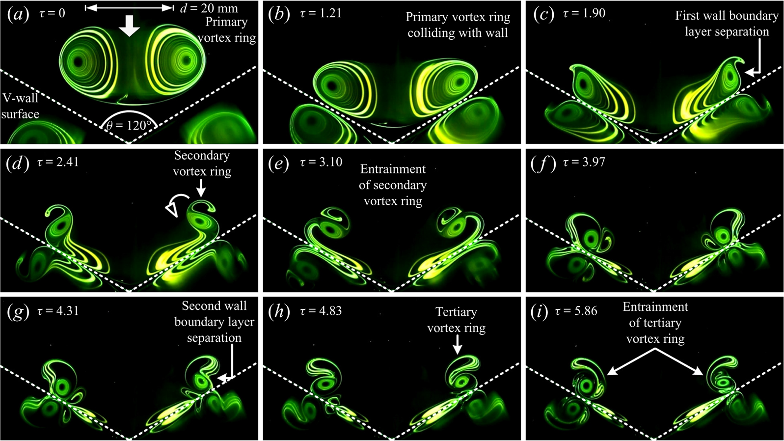
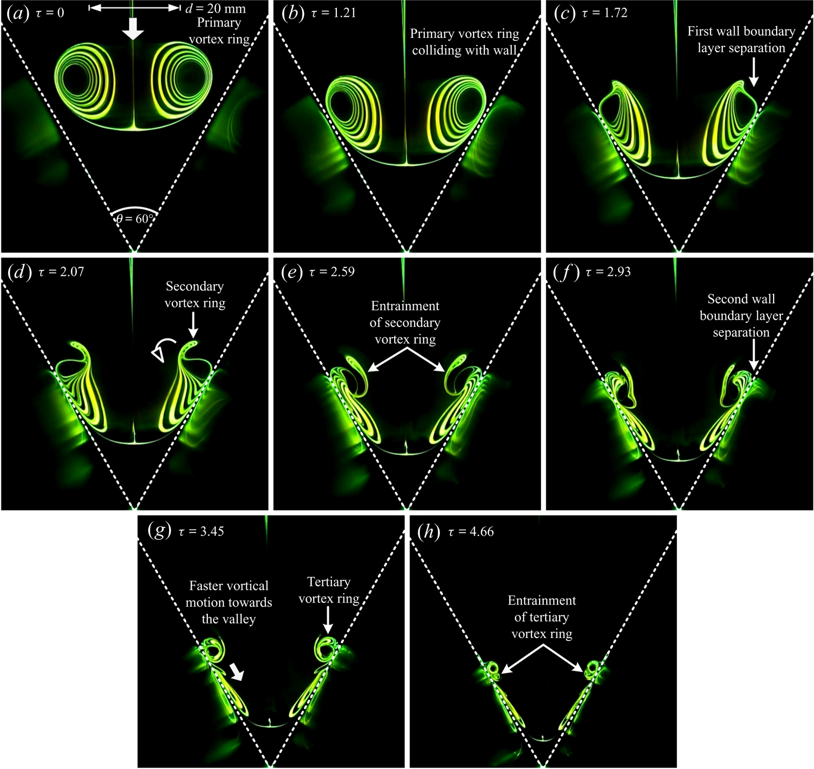
Time-sequenced LIF images of a  ${Re} =2000$ vortex ring colliding upon the
 $\theta =120^{\circ }$ V-wall. General flow behaviour resembles that of a flat-wall collision, except that entrainment and merging of secondary and tertiary vortex-ring cores by the primary vortex-ring cores are more accentuated.

Similar to the study conducted by New & Zang (Reference New and Zang2017), it has to be highlighted that careful alignments between the vortex rings and the V-walls are crucial to achieving satisfactorily symmetrical and well-defined flow details, especially for smaller included angles. Furthermore, it should also be noted that the effective wall inclination angles (i.e. relative to the image horizontal here) for the  $\theta =30^{\circ }$, 60
 $^{\circ }$, 90
 $^{\circ }$ and 120
 $^{\circ }$ V-walls here are equivalent to those for the
 $\theta =75^{\circ }$, 60
 $^{\circ }$, 45
 $^{\circ }$ and 30
 $^{\circ }$ inclined walls studied earlier (New et al. Reference New, Shi and Zang2016). Hence, it will be logical to draw comparisons between the results captured in the present study with those reported by New et al. (Reference New, Shi and Zang2016) previously and infer where appropriate. Lastly, it should also be highlighted that the first flow images in figures 3–6 are associated with primary vortex rings that are not yet discernibly distorted by their proximity to the wall and taken as initial points of reference in terms of time and descriptions of the observed flow dynamics.
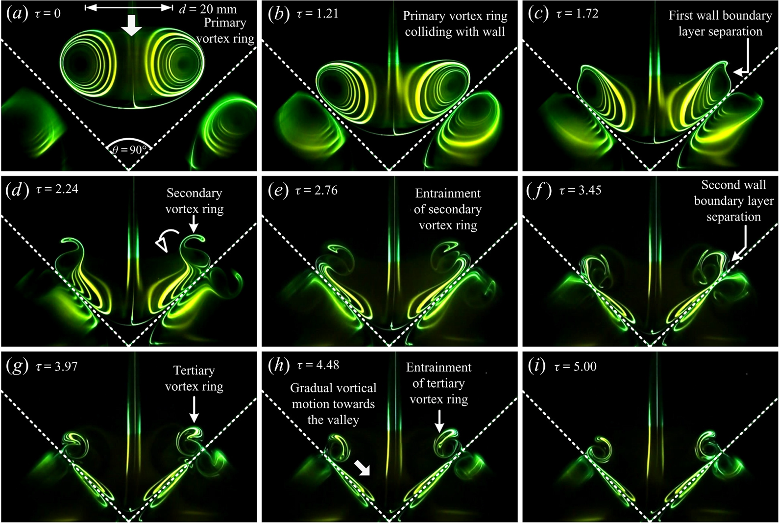
Time-sequenced LIF images of a  ${Re} =2000$ vortex ring colliding upon the
 $\theta =90^{\circ }$ V-wall. Flow developments remain relatively similar to that observed for
 $\theta =120^{\circ }$ V-wall collision, although the primary vortex-ring cores entrain the secondary and tertiary vortex-ring cores more rapidly now.
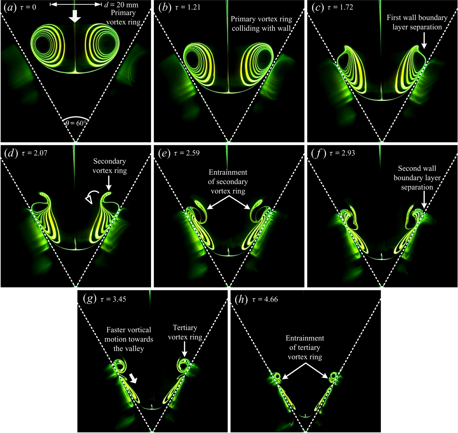
Time-sequenced LIF images of a  ${Re} =2000$ vortex ring colliding upon the
 $\theta =60^{\circ }$ V-wall. Note the increased rate at which the secondary vortex-ring cores are being ingested by and merged with the primary vortex-ring cores and reduction in vortex-core sizes.
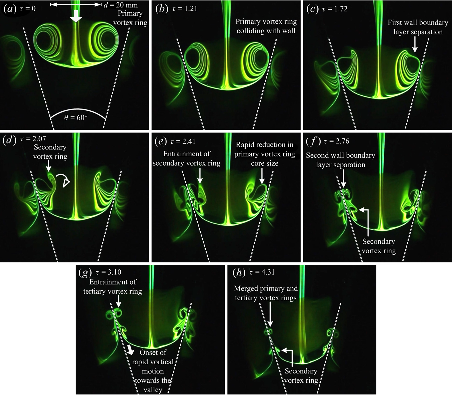
Time-sequenced LIF images of a  ${Re} =2000$ vortex ring colliding upon the
 $\theta =30^{\circ }$ V-wall. Note the continuing passage of the secondary vortex ring towards the valley after it has been entrained by the primary vortex ring, as well as the drastic reductions in all the vortex-core sizes.
Starting with the  $\theta =120^{\circ }$ V-wall shown in figure 3, where the physical configuration is closest to that of a flat wall (i.e.
 $\theta =180^{\circ }$), distortions to the primary vortex-ring cores and expansion of the ring diameter shortly after the collision unsurprisingly resemble closely those observed for flat-wall collisions (see supplementary movie 1 available at https://doi.org/10.1017/jfm.2020.425). Comparing with New et al. (Reference New, Shi and Zang2016), the primary vortex-ring diameter does not increase as much after collision as in the case for flat-wall collisions, as it is constrained by the V-wall here. Subsequently, wall boundary layer separation under an adverse pressure gradient caused by the presence of the primary vortex ring leads to the formation of secondary vortex-ring cores, as well as their entrainment by the primary vortex ring shortly after the collision (see figure 3a–e). Unlike flat-wall collisions, though, the secondary vortex-ring cores merge with the primary vortex-ring cores more rapidly once they are within the confines of the latter (see figure 3f–h). A second wall boundary layer separation occurs during the entrainment of the secondary vortex-ring cores and leads to the formation of weak tertiary vortex-ring cores, which get ingested by the primary vortex-ring cores as well (see figure 3g–i). It should be highlighted that the entrainment process is visually more accentuated even for this wall with a relatively large included angle, as compared to flat-wall collisions. Furthermore, the primary vortex-ring cores convect slightly towards the vertex of the valley after the preceding flow developments, presumably under flow inertia. As the included angle reduces to
 $\theta =90^{\circ }$ as shown in figure 4, the vortical changes are similar to those observed for the
 $\theta =120^{\circ }$ V-wall collision earlier on, though the entrainment and merging of the secondary and tertiary vortex-ring cores by the primary vortex ring are now more rapid (see supplementary movie2).
At this point, it should not come as a surprise that the above-mentioned behaviour becomes even more intense as the included angle reduces to  $\theta =60^{\circ }$ (see supplementary movie 3), as shown in figure 5. This is particularly the case for the entrainment of secondary and tertiary vortex-ring cores by the primary vortex-ring cores, and as well as the higher rates at which the physical sizes of the various vortex-ring cores are reduced as the flow develops. However, what is more interesting with this configuration is that only the secondary vortex-ring cores merged with the primary vortex ring. In this case, the entrained tertiary vortex-ring cores do not merge with the primary vortex-ring cores but continue to convect down along the walls (see figure 5g–h). And if the included angle reduces further to
 $\theta =30^{\circ }$, the flow behaviour becomes more intriguing (see supplementary movie 4). Firstly, the secondary vortex-ring cores do not merge with the primary vortex ring completely after they are entrained by the latter. Instead, parts of them convect past the primary vortex-ring cores and continue to convect along the walls towards the vertex of the valley (see figure 6e–g). At the same time, tertiary vortex-ring cores can be observed to form from a second boundary layer separation. Unlike the secondary vortex-ring cores, however, the tertiary vortex-ring cores are completely entrained by and merged with the primary vortex-ring cores (see figure 6f–g). Subsequently, both the primary and secondary vortex-ring cores move towards the vertex of the valley, while shrinking in physical size at the same time.
From the preceding visualization results, it can be surmised that the use of an increasingly smaller included angle produces a few interesting alterations to the typical flow behaviour established for flat-wall collisions. Firstly, the secondary vortex-ring cores are gradually able to escape being completely ingested by and merged with the primary vortex-ring cores after their entrainment as the included angle decreases. Secondly, the secondary vortex-ring cores subsequently interact more with the boundary layer ahead of the primary vortex ring (i.e. along the wall regions closer to the vertex of the valley). Lastly, the reduction in the various vortex-ring core sizes increases rapidly as the included angle becomes smaller. In fact, this observation indicates that these vortex-ring structures undergo significant stretching effects and movements out of the valley plane in opposite directions (i.e. symmetrically along the orthogonal plane), due to physical constraints imposed by the V-walls. As visualization results along the orthogonal plane will show later, that is indeed the case.
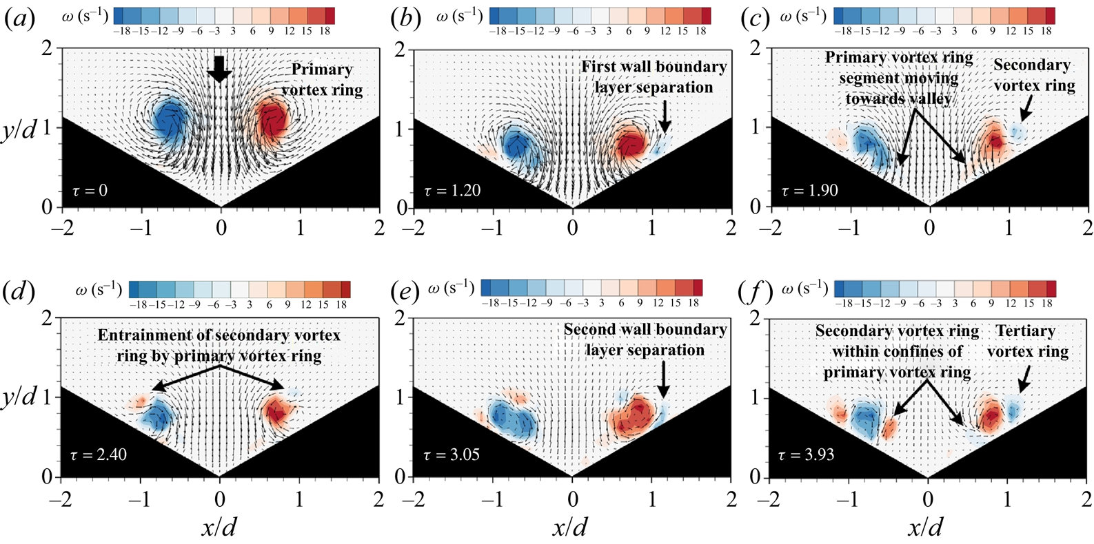
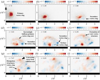
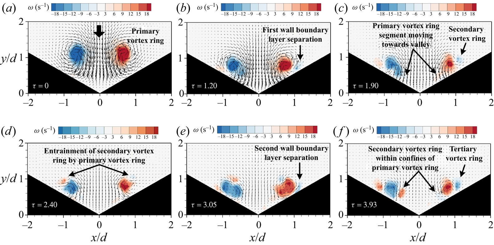
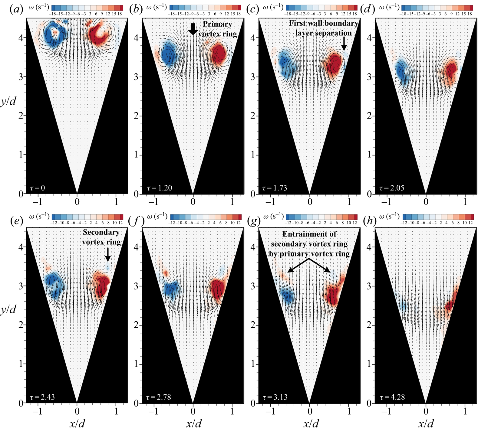
To complement the scalar dye-based flow visualizations and for a more quantitative appreciation of the flow changes, vorticity maps of the preceding flow scenarios obtained through TR-PIV measurements are presented in figures 7 and 8. For the sake of brevity, only the results associated with  $\theta =120^{\circ }$ and 30
 $^{\circ }$ V-walls are shown here, as they reveal the most significant flow changes produced by a drastic reduction in the included angle. Figure 7 shows that the collision behaviour of the primary vortex ring, the formation of secondary and tertiary vortex-ring cores and their subsequent entrainment by the primary vortex-ring cores for the
 $\theta =120^{\circ }$ V-wall are successfully captured and compare well with the earlier visualization images. Owing to the need to cover a certain measurement region size for the translating vortex ring during the TR-PIV measurements, as well as the fact that the tertiary vortex-ring cores become increasingly physically smaller as the included angle reduces (see figures 5 and 6), the current measurement resolution is not sufficiently high to capture the tertiary vortex-ring cores for the
 $\theta =60^{\circ }$ and 30
 $^{\circ }$ V-walls here. Nonetheless, the vorticity results for the
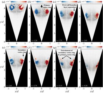
 $\theta =30^{\circ }$ wall, as shown in figure 8, demonstrate quantitatively the intense interactions between the various vortex-ring cores, especially during the entrainment process. Lastly, the velocity vectors depicted in these results also show that flow inertia from the primary vortex ring provides the flow momentum that keeps the various vortex-ring cores moving towards the vertex of the valley, even as they are engaged in mutual interactions. Hence, unlike the case for flat-wall collisions, the presence of a background translation velocity while vortical changes remain confined renders the present collision behaviour more three-dimensional and complex.
Time-sequenced vorticity maps of a  ${Re} =2000$ vortex ring colliding upon the
 $\theta =120^{\circ }$ V-wall. Note that vortical changes such as wall boundary layer separations, formation of secondary and tertiary vortex-ring cores and their subsequent entrainment by the primary vortex ring cores are captured.
Time-sequenced vorticity maps of a  ${Re} =2000$ vortex ring colliding upon the
 $\theta =30^{\circ }$ V-wall. Similar to figure 6, vortical changes and interactions occur very rapidly once the primary vortex ring collides with the V-wall.
3.2. Effects of vortex-ring Reynolds number
It is observed during the present study that increasing the Reynolds number has a direct impact upon the behaviour of the secondary and tertiary vortex-ring cores after they leapfrog past the primary vortex-ring cores when the included angle is small. Recall the case for flat-wall collisions, where they will remain within the confines of the primary vortex ring and transit to incoherence thereafter: an increase in Reynolds number primarily serves to accelerate the flow developments and transition to incoherence (Walker et al. Reference Walker, Smith, Cerra and Doligalski1987; Verzicco & Orlandi Reference Verzicco and Orlandi1994; Swearingen et al. Reference Swearingen, Crouch and Handler1995; Naitoh et al. Reference Naitoh, Banno and Yamada2001; Cheng etal. Reference Cheng, Lou and Luo2010; New et al. Reference New, Shi and Zang2016). In the present flow configuration, however, a combination of higher Reynolds number and smaller included angle (i.e. in particular the latter) is able to lead to the formation of new vortex structures and behaviour not observed previously. For  $\theta =120^{\circ }$ and 90
 $^{\circ }$ V-wall collisions with
 ${Re} =4000$ vortex rings, the key flow developments of the vortex-ring collisions do not differ much from those observed at
 ${Re} =2000$, except for being more rapid (hence, results are not shown for the sake of brevity). The more notable difference will be that a third boundary layer separation occurs after the formation of the tertiary vortex ring to produce a second set of tertiary vortex-ring cores. Together with the first set of tertiary vortex-ring cores, the second set of tertiary vortex-ring cores gets ingested by and merged with the primary vortex-ring cores after entrainment. For
 $\theta =60^{\circ }$ and 30
 $^{\circ }$ V-wall collisions with
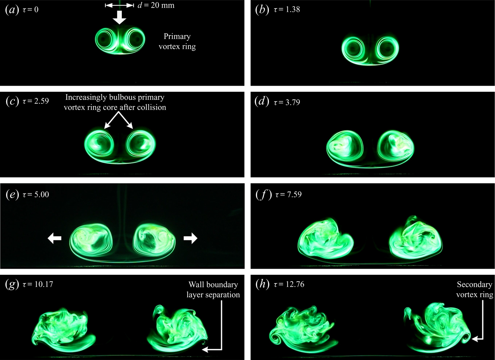
 ${Re} =4000$ vortex rings, however, other than the expected boundary layer separations after the collision that produce the secondary and tertiary vortex-ring cores, their rapid entrainment by the primary vortex-ring cores also leads to further intriguing observations. In particular, when the entrained secondary and/or tertiary vortex-ring cores do not merge with the primary vortex-ring cores, they produce previously unseen vortex structures when they leapfrog and impinge upon the walls ahead of the primary vortex-ring cores.
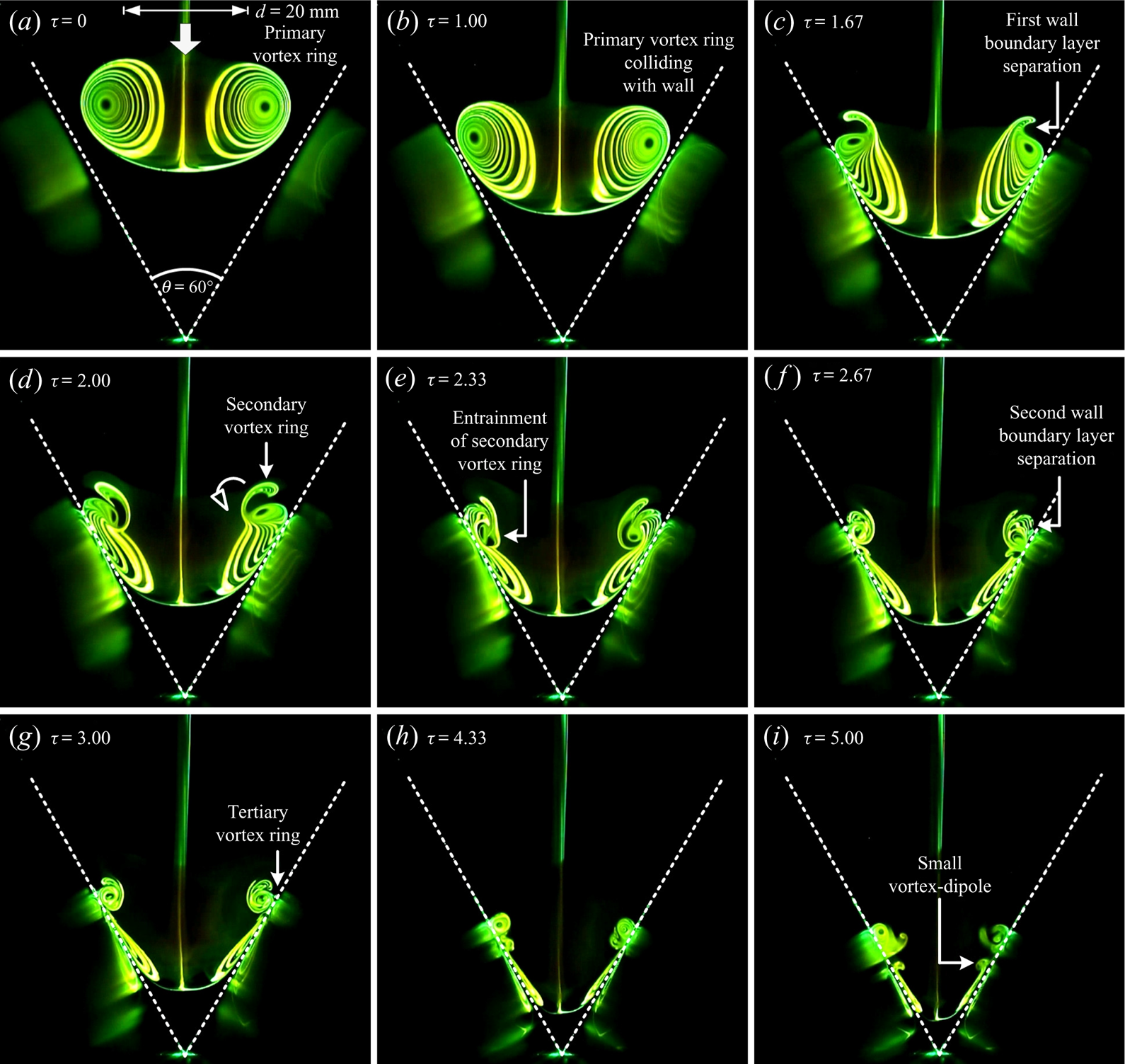
Take for instance, as can be seen in figure 9 for the  $\theta =60^{\circ }$ wall, the impingement of the tertiary vortex-ring cores along the wall ahead of the primary vortex-ring cores after the former have been entrained by the latter: this leads to the interesting appearance of small mushroom-shaped vortex dipoles in figure 9(i). Playbacks of LIF video recordings associated with figure 9 suggest that the presence of the tertiary vortex-ring cores along the V-wall surfaces (after the preceding behaviour) leads to adverse pressure gradients upstream of the primary vortex-ring cores. This in turn produces wall boundary layer separations and wall-separated vortex structures that possess rotational senses that are opposite to those of the tertiary vortex-ring cores, much like what happens when the primary vortex-ring cores lead to the formation of secondary vortex-ring cores. Subsequently, each tertiary vortex-ring core pairs up with each of these opposite-signed vortex structures along each V-wall surface to form a small-scale vortex dipole, which convects towards the vertex of the valley under flow inertia. For the smallest included angle of
 $\theta =30^{\circ }$, the primary vortex-ring cores encounter the wall soon after they are formed, which leads to comparatively earlier formation of the secondary vortex-ring cores (i.e.
 $\tau =1.33$ and 1.67 for 30
 $^{\circ }$ and 60
 $^{\circ }$ V-walls, respectively; see figure 10a–d) and their entrainment by the primary vortex-ring cores (i.e.
 $\tau =1.67$ and 2.33 for 30
 $^{\circ }$ and 60
 $^{\circ }$ V-walls, respectively). Note that more detailed information and analysis on these timings will be presented and discussed later. In this case, however, the entrainment process distorts both the primary and secondary vortex-ring cores significantly, probably reinforced by the much higher wall shear stresses associated with the more inclined V-wall here. Subsequently, the entrained secondary vortex-ring cores impinge upon the wall after their entrainment and this leads to the formation of new wall-separated vortex structures downstream of it, where their formations would be similar to what has been described earlier.
Time-sequenced LIF images of a  ${Re} =4000$ vortex ring colliding upon the
 $\theta =60^{\circ }$ V-wall. Interesting formations of small-scale vortex dipoles by the tertiary vortex-ring cores and a wall-separated vortex upstream of the primary vortex-ring cores can be seen here.
Time-sequenced LIF images of a  ${Re} =4000$ vortex ring colliding upon the
 $\theta =30^{\circ }$ V-wall. Multiple instances of small-scale vortex dipoles can be observed here, suggesting higher Reynolds number and smaller included angle to be conducive towards their formation.

3.3. Vortical developments along the orthogonal plane
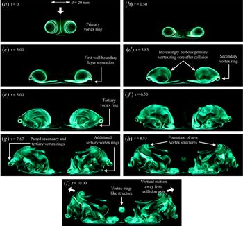
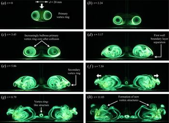
Flow visualization images taken for  ${Re} =2000$ vortex-ring collisions but along the orthogonal plane for
 $\theta =120^{\circ }$, 90
 $^{\circ }$, 60
 $^{\circ }$ and 30
 $^{\circ }$ V-walls are now presented in figures 11 to 14, respectively. Note that the laser sheet was aligned along the inner edge of the valley and
 $XZ$ plane, with the camera facing it. Out of the four configurations, the vortex dynamics associated with the
 $\theta =120^{\circ }$ V-wall are visually the clearest and most intricate. Furthermore, flow developments for the
 $\theta =120^{\circ }$ and 90
 $^{\circ }$ V-walls appear to be quite different from those of the
 $\theta =60^{\circ }$ and 30
 $^{\circ }$ V-walls along this plane. Hence, subsequent discussions will be differentiated between these two sets of included angles.
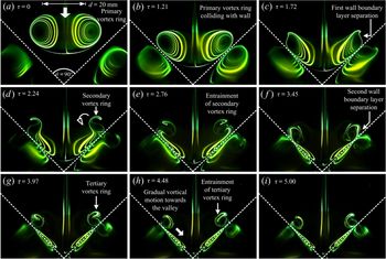
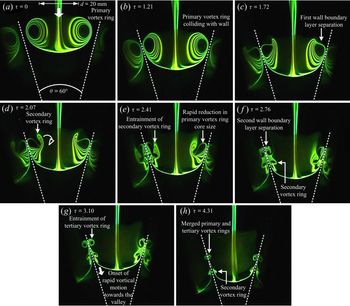
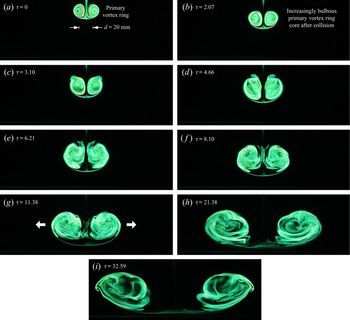
Time-sequenced LIF images taken along the orthogonal plane for a  ${Re} =2000$ vortex ring colliding upon the
 $\theta =120^{\circ }$ V-wall. The formation of secondary and multiple tertiary vortex-ring cores can be observed after the collision, along with other flow developments that give rise to new vortex structures along the top side of the primary vortex ring and a small vortex-ring-like structure along the collision axis.

To start things off, figure 11 shows the primary vortex ring colliding with the V-wall with its cores moving away from the collision axis (see supplementary movie 5). It should be mentioned that the movements of the primary vortex-ring cores away from the collision axis are more rapid and greater than those observed previously for flat-wall collisions by New et al. (Reference New, Shi and Zang2016) for the same primary vortex-ring initial condition. During the same time, the boundary layer separates under adverse pressure gradients caused by the vortex-ring cores outward movements to produce secondary vortex-ring cores (see figure 11a–d). While these are occurring, the primary vortex-ring cores can also be observed to grow increasingly bulbous and incoherent, while multiple instances of increasingly weaker tertiary vortex rings are produced from additional boundary layer separations (see figure 11e–g). Subsequently, and more interestingly, the flow field reorganizes and coherent vortex structures gradually form along the top peripheral regions of the increasingly turbulent primary vortex-ring cores (see figure 11h). Intriguingly, these vortex structures move away from the collision axis and, in doing that, resemble two large-scale mushroom-shaped structures moving away from each other. Of particular interest here will be the formation of a small vortex-ring-like structure along the collision axis and approximately  $1D$ above the inner edge (see figure 11i).
As the included angle reduces to  $\theta =90^{\circ }$, as shown in figure 12, the flow behaviour remains largely similar with some notable exceptions (see supplementary movie 6). Firstly, secondary vortex-ring cores form later and only after the primary vortex-ring cores have bulged and become incoherent (see figure 12d). Secondly, no discernible tertiary vortex-ring cores are observed to form, though they could in principle be very weak and did not entrain sufficient fluorescent dye to be observed clearly. Thirdly, the secondary vortex-ring cores appear to pair up with other flow structures as a result of the underlying vortex dynamics and lead to vortex dipoles forming along the sides of the now largely incoherent primary vortex-ring cores (see figure 12 f,g). Note that these vortex dipoles are different from the vortex structures that appear along the top peripheral region of the primary vortex-ring cores observed earlier in figure 11(h), as the current ones only appear significantly later, as shown in figure 12(h). Lastly, the small-scale vortex-ring-like structure along the collision axis now forms nearer to the inner edge at approximately
 $0.5D$ above it.
Time-sequenced LIF images taken along the orthogonal plane for a  ${Re} =2000$ vortex ring colliding upon the
 $\theta =90^{\circ }$ V-wall. The flow images depict flow behaviour and structures relatively similar to those observed in figure 11, down to the top-side vortex structures and small vortex-ring-like structure.

If the included angle reduces further to  $\theta =60^{\circ }$ and 30
 $^{\circ }$, as shown in figures 13 and 14 (see supplementary movies 7 and 8), it can be observed that the primary vortex-ring cores bulge and transit to turbulence rapidly even before they come close to the wall inner edge (see figures 13a–e and 14a–h). It should be noted that a small pair of vortex structures can be observed to form above the primary vortex-ring cores in figures 13(e, f) and 14(c,d), probably caused by the earlier formations of the secondary vortex ring and its entrainment by the primary vortex ring along the V-wall surfaces, which then propagates from the walls towards the orthogonal plane. However, they appear to merge with the increasingly bulbous primary vortex-ring cores very rapidly after appearing, which will agree with what was observed in the flow visualizations presented earlier in figures 5 and 6. When the primary vortex-ring cores eventually reach the vertex of the valley however, additional wall boundary layer separations occur to produce pairs of vortex structures that resemble very much the secondary vortex-ring cores observed in figures 11 and 12. However, since it has been established earlier on that the secondary vortex ring forms much earlier along the V-wall surfaces, it stands to argue that these vortex structures are visualizations of the same secondary vortex ring that are fully formed when primary vortex-ring segments along the orthogonal plane finally impact upon the wall inner edge. It would appear at this point that the use of a V-wall with an increasingly smaller included angle will introduce a correspondingly larger phase lag in the formation of secondary vortex-ring segments along the V-wall surface and wall inner edge. A smaller included angle will result in a ‘narrower’ wall and hence introduce a larger discrepancy in the locations and times at which different primary vortex-ring segments will come into physical contact with the V-wall surfaces and inner edge. For the present flow conditions, the critical included angle appears to be approximately between
 $\theta =60^{\circ }$ and 90
 $^{\circ }$. Returning to figures 13 and 14, no discernible tertiary vortex-ring cores and vortex dipoles like those observed for larger included angles result from these collision scenarios, and certainly no small vortex-ring-like structures are formed along the collision axis at any point during these flow visualizations.
Time-sequenced LIF images taken along the orthogonal plane for a  ${Re} =2000$ vortex ring colliding upon the
 $\theta =60^{\circ }$ V-wall. The primary vortex-ring cores transit to incoherence earlier with no formation of tertiary vortex-ring cores and top-side vortex structures observed.

Time-sequenced LIF images taken along the orthogonal plane for a  ${Re} =2000$ vortex ring colliding upon the
 $\theta =30^{\circ }$ V-wall. Images show a behaviour that is similar to that depicted in figure 13, except that the primary vortex-ring cores become incoherent and secondary vortex-ring cores are formed very shortly after the former collide with the V-wall surfaces. Significant movements away from the collision axis incurred by the primary vortex-ring cores can also be clearly observed here.

The behaviour of the primary vortex-ring cores when the included angle reduces to  $\theta =60^{\circ }$ and smaller may be better appreciated if one considers earlier studies by Lim (Reference Lim1989), Verzicco & Orlandi (Reference Verzicco and Orlandi1994) and Cheng et al. (Reference Cheng, Lou and Luo2010) on the dynamics of vortex-ring collisions on inclined walls. Their studies revealed that such collisions lead to dissimilar stretching along the vortex-ring filament and compression of bi-helical lines. This behaviour in turn produces circumferential flows that move from the vortex-ring segment that collides with the inclined wall first, towards the diametrically opposite vortex-ring segment that collides with the inclined wall later. With that in mind, consider also the fact that each of the inclined surfaces associated with the
 $\theta =60^{\circ }$ and 30
 $^{\circ }$ V-walls here have the same effective inclinations as the
 $\theta =60^{\circ }$ and 75
 $^{\circ }$ inclined walls, respectively, investigated by New et al. (Reference New, Shi and Zang2016), which can certainly be treated as highly inclined and produce very significant circumferential flows. Inferring from results obtained by the above-mentioned studies, circumferential flows from the collided primary vortex-ring segments (i.e. starting from both V-wall surfaces) towards segments that have not collided with the V-wall surfaces (i.e. ending along the present orthogonal plane) are expected to be very significant at small included angles. It should be noted that earlier results by New et al. (Reference New, Shi and Zang2016) demonstrated the significant extent of circumferential flow when the same vortex ring collides with an inclined wall, so the presence of two inclined surfaces that formed each V-wall will only serve to accentuate the circumferential flows. As a result, severe compression of vortex lines occurring right along the orthogonal plane will account for the rapid transition towards flow incoherence. Owing to the marked increase in the rate at which the primary vortex ring evolves and transits into incoherence under the present scenario, scalar dye might not have tracked all the key flow developments. To understand better, vorticity distributions from TR-PIV measurements along the orthogonal plane are now presented in figures 15 and 16. Note that, since earlier flow visualization results have shown that the general flow behaviour can be differentiated between
 $\theta \leqslant 60^{\circ }$ and
 $\theta \geqslant 90^{\circ }$ V-walls, only the results for
 $\theta =120^{\circ }$ and 30
 $^{\circ }$ V-walls will be shown here for the sake of brevity. In figure 15, where results for
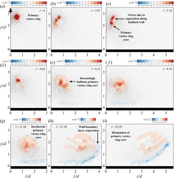
 $\theta =120^{\circ }$ V-wall are shown, the vorticity maps depict flow developments that are in good agreement with what was observed during the flow visualizations in figures 11 and 12, further reinforcing the notion that the flow dynamics does not differ much between these two configurations. Not only do these results show the primary vortex-ring cores becoming more bulbous and incoherent after the collision, they also successfully captured the formation of the secondary and tertiary vortex-ring cores (see figure 15d,e). In particular, they show that the new vortex structures that form along the top peripheral region of the primary vortex ring are likely to be part of the latter as it undergoes vortical changes (see figure 15f). The movements of these new vortex structures away from the collision axis have also been captured (see figure 15g–i). On the other hand, the small vortex-ring-like structures along the collision axis are not captured in these results, presumably due to their very small physical sizes and highly transient nature.
Time-sequenced TR-PIV vorticity distributions along the orthogonal plane for a  ${Re} =2000$ vortex-ring colliding upon the
 $\theta =120^{\circ }$ V-wall. Quantitative evidence for the secondary and tertiary vortex-ring core formation, a new vortex structure along the top side of the primary vortex-ring core and its movement away from the collision axis can be observed here and agree with flow visualizations in figure 11.

Time-sequenced TR-PIV vorticity distributions along the orthogonal plane for a  ${Re} =2000$ vortex-ring colliding upon the
 $\theta =30^{\circ }$ V-wall. The flow structures and behaviour resemble closely the corresponding flow visualizations in figure 14.

In contrast, figure 16 shows the primary vortex ring colliding upon the  $\theta =30^{\circ }$ V-wall and transiting towards incoherence at some distance away from the wall inner edge, similar to the flow visualizations presented earlier in figures 13 and 14. In particular, the vorticity maps successfully captured the early formation of a pair of vortex structures along the top side of the primary vortex-ring cores early into the flow at significant distances away from the wall inner edge at the bottom, which result in the formation of two vortex cores of similar rotational senses early in the collisions (see figure 16c). Discussions earlier on have indicated that they are cross-sections of the secondary vortex ring formed by the much earlier wall boundary layer separations along the V-wall surfaces that propagate towards the orthogonal plane. Subsequent vorticity maps show them merging with the primary vortex-ring cores as one single increasingly incoherent vortical entity impacting upon the inner edge eventually. Thereafter, wall boundary layers separate along this plane to produce the second instance of secondary vortex rings.
3.4. Circulation variations
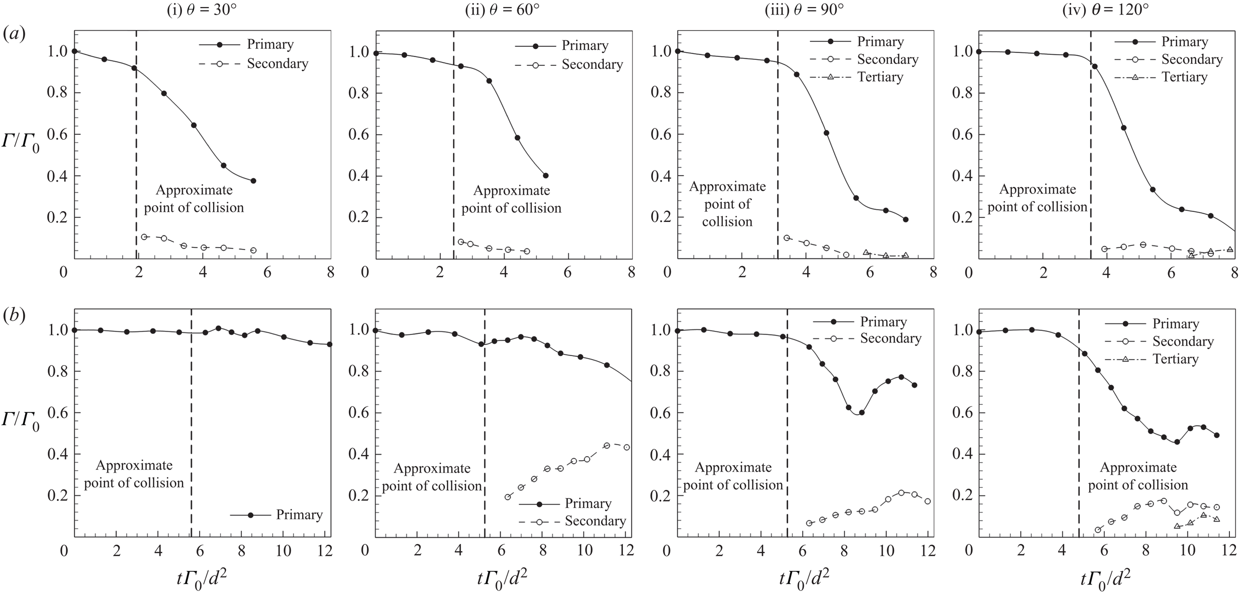
In this section, changes to the circulation levels of the primary, secondary and tertiary vortex-ring cores will be presented and discussed. Figure 17 shows non-dimensionalized circulations associated with these vortex structures determined along the valley and orthogonal planes plotted against non-dimensionalized times. The circulation levels,  $\Gamma$, were determined according to the procedures described in New & Zang (Reference New and Zang2017), where the TR-PIV vorticity fields were integrated over the vortex-core areas through the use of Stokes theorem. It is worth pointing out that, though these circulation levels were derived from two-dimensional TR-PIV measurements, they will provide some indicative information on how the included angle affects the vortex dynamics and structures. The absolute circulation levels were subsequently non-dimensionalized by
 $\Gamma _0$, where the latter is the reference circulation level of the primary vortex ring after it was fully formed but before it was influenced by the presence of the V-wall (in the present study,
 $2.5d$ from the apex of the V-walls for
 $\theta =120^{\circ }$ and 90
 $^{\circ }$ V-walls, and
 $3d$ and
 $4d$ for
 $\theta =60^{\circ }$ and 30
 $^{\circ }$ V-walls, respectively). On the other hand, time
 $t$ was non-dimensionalized by
 $\Gamma _0/d^2$ and this non-dimensionalization was in accordance with the vortex-ring studies conducted earlier by Cheng et al. (Reference Cheng, Lou and Luo2010, Reference Cheng, Lou and Lim2014). The approximate times of vortex-ring collisions are indicated as vertical dashed lines in the plots to better differentiate the circulation changes before and after the collisions.
Changes to the primary, secondary and tertiary vortex-ring core circulation levels along the valley and orthogonal planes as the included angle varies from  $\theta =30^{\circ }$ to 120
 $^{\circ }$. Approximate points of collisions are indicated in the plots to better highlight when the primary vortex ring collides with the V-walls. Note that the circulation levels are only determined when the vortex cores are sufficiently discernible from the TR-PIV measurements.

Figure 17(a) shows the primary and secondary vortex-ring core circulation variations along the valley plane as the included angle increases from  $\theta =30^{\circ }$ to 120
 $^{\circ }$. At first glance, it can be observed that the primary vortex-ring core circulation becomes increasingly more affected even before colliding with the V-wall as the included angle decreases. Specifically, it can be seen in figure 17(a(i)–(iii)) that reductions in the primary vortex-ring core circulation levels increase as the primary vortex ring translates towards the
 $\theta =90^{\circ }$, 60
 $^{\circ }$ and 30
 $^{\circ }$ V-walls. In contrast, this is hardly the case for the
 $\theta =120^{\circ }$ V-wall, where the primary vortex-ring core circulation remains relatively constant before the collision. Such an observation can be attributed to the increasingly more adverse pressure gradients set up by V-walls with progressively smaller included angles, due to the physical limitations imposed by the enclosed valleys. After the collisions, however, the primary vortex-ring core circulation decreases dramatically in a similar fashion as with vortex-ring collisions upon flat walls, where a more rapid reduction is associated with a larger included angle. This circulation reduction is associated with heightened vortex stretching caused by primary vortex-ring segments continuing to translate towards the wall inner edge, as well as other segments translating out of the orthogonal plane due to the confined boundary. However, it can also be seen that the primary vortex-ring core circulations for
 $\theta =90^{\circ }$ and 120
 $^{\circ }$ V-walls tend to approach a relatively ‘plateau’ level of approximately 20 % of the initial value (i.e. before the collision) at
 $t\Gamma _0/d^2\approx 6$, where further reductions can be attributed to gradual viscous dissipation.
In contrast, for  $\theta =30^{\circ }$ and 60
 $^{\circ }$ V-walls, rapid reductions in the primary vortex-ring core sizes mean that it is not possible to determine the primary vortex-ring circulations reliably from the TR-PIV measurements from
 $t\Gamma _0/d^2\approx 5.5$ onwards. Nevertheless, together with the experimental results presented earlier, the primary vortex-ring core circulations for
 $\theta =30^{\circ }$ and 60
 $^{\circ }$ V-walls are not expected to demonstrate a ‘plateau’-like behaviour at any point in time. Instead, all the evidence points towards rapid reductions in the circulation level due to stronger vortex-stretching behaviour associated with smaller included angles. Recall that earlier works by Lim (Reference Lim1989) and New et al. (Reference New, Shi and Zang2016) demonstrated strong circumferential flows along the vortex-ring filament, starting from the vortex-ring segment that first collides with an inclined wall to the diametrically opposite segment. Lastly, secondary vortex-ring core circulations are significantly lower regardless of the included angle, staying between approximately 5 % and 10 % of the initial primary vortex-ring circulation.
As for the circulation behaviour along the orthogonal plane as depicted in figure 17(b), there are discernible trends as the included angle varies as well. In particular, similar to the circulation behaviour along the valley plane discussed above, the circulation behaviour appears to be distinguishable between smaller (i.e.  $\theta =30^{\circ }$ and 60
 $^{\circ }$) and larger included angles (i.e.
 $\theta =90^{\circ }$ and 120
 $^{\circ }$) here. For
 $\theta =30^{\circ }$ and 60
 $^{\circ }$ V-walls, the primary vortex-ring circulation undergoes a relatively straightforward gentle reduction after it collides with the V-wall, where a smaller included angle leads to a smaller reduction. Additionally, it should be noted that it was difficult to reliably estimate the circulation of the secondary vortex-ring cores for the
 $\theta =30^{\circ }$ V-wall, due to their small physical sizes and resolution limitations in the TR-PIV measurements, even though secondary vortex-ring cores do appear in figures 14 and 16. Nonetheless, secondary vortex-ring core circulations are successfully estimated for the
 $\theta =60^{\circ }$ V-wall and they can be observed to increase once the secondary vortex-ring cores are formed. In fact, the peak circulation level is more than double the initial value.
As for  $\theta =90^{\circ }$ and 120
 $^{\circ }$ V-walls, while the primary vortex-ring core circulations along the orthogonal plane reduce rapidly after the collisions, as expected, they begin to increase after reaching a minimum value. Having said that, the increments reach a maximum and the circulation levels decrease thereafter. This behaviour has not been observed in vortex-ring collisions upon a flat wall under similar flow conditions (New & Zang Reference New and Zang2017), or for
 $\theta =30^{\circ }$ and 60
 $^{\circ }$ V-walls under the current experimental conditions. At this point in time, it is postulated that the differences in the circulation behaviour can be attributed to the rate of vortex compression along the orthogonal plane between
 $\theta =30^{\circ }$ and 60
 $^{\circ }$ and
 $\theta =90^{\circ }$ and 120
 $^{\circ }$ V-walls. Note that it has already been established from earlier experimental evidence that these two sets of V-walls lead to generally different flow behaviour. For
 $\theta =30^{\circ }$ and 60
 $^{\circ }$ V-walls, the much earlier collisions of primary vortex-ring segments with the V-wall surfaces will lead to earlier initiation of circumferential flow along the vortex-ring filament and hence vortex compression along the orthogonal plane. As such, this results in significant influx of compressed bi-helical lines around the primary vortex-ring cores towards the orthogonal plane shortly after the collisions with the V-wall surfaces. Furthermore, the earlier collisions with the V-wall surfaces limit the extents to which the primary vortex-ring cores move away from the collision axis and hence vortex stretching. These are likely to account for the much more gradual decreases in the overall primary vortex-ring circulations along the orthogonal plane than those along the valley plane. It has to be noted at this point that, due to the influx of compressed bi-helical lines occurring within close proximity of the primary vortex-ring cores, changes in the estimated circulation levels of the primary vortex-ring cores along the orthogonal plane should be approached with care. The use of two-dimensional TR-PIV measurement results here to estimate circulation levels means that it is not possible to distinguish between the local vorticities associated with the actual primary vortex-ring cores and compressed bi-helical lines. Hence, the overall primary vortex-ring core circulation should be treated as the total circulation arising from both vortical entities when vortex compression exists along the measurement plane, as opposed to the actual primary vortex-ring circulation.
As for  $\theta =90^{\circ }$ and 120
 $^{\circ }$ V-walls, they produce more gradual vortex compression along the orthogonal plane due to smaller discrepancies between the times when the primary vortex-ring segments collide with the V-wall surfaces and the vertex of the valley. Additionally, their significantly larger included angles allow the primary vortex-ring cores to move further away from the collision axis and hence comparatively higher levels of vortex stretching over the
 $\theta =30^{\circ }$ and 60
 $^{\circ }$ V-walls. Based on figure 17(b(iii),b(iv)), it is postulated that the vortex-stretching effects dominate over the more modest vortex-compression effects, such that the overall primary vortex-ring circulations decrease for both
 $\theta =90^{\circ }$ and 120
 $^{\circ }$ V-walls. This will agree well with the observation that the
 $\theta =120^{\circ }$ V-wall produces a lower minimum overall primary vortex-ring core circulation level than the
 $\theta =90^{\circ }$ V-wall, since the former will produce comparatively lower vortex compression and larger movements of the primary vortex-ring cores due to the larger included angle. The small increments in the overall primary vortex-ring core circulations after they reached minimum levels may seem to run counter to Kelvin's theorem, where they should not increase due to the preservation of circulation principle. However, as mentioned earlier, the estimated circulation levels here cannot differentiate contributions due to vorticities from the actual primary vortex-ring cores and compressed bi-helical lines. Hence, even as the primary vortex-ring cores cease to move away from the collision axis with reduced vortex-stretching levels due to significant interactions with the secondary and tertiary vortex-ring cores, the continuing influx of compressed bi-helical lines towards the orthogonal plane will eventually drive up the overall primary vortex-ring core circulation. Note the smaller extent to which the overall primary vortex-ring core circulation reaches its maximum level after the increment for the
 $\theta =120^{\circ }$ V-wall as compared to the
 $\theta =90^{\circ }$ V-wall, which could be explained by lower vortex compression levels conferred by a larger included angle V-wall. Last but not least, secondary vortex-ring core circulation levels for these two V-walls are significantly lower than their corresponding primary vortex-ring core counterparts and that of the
 $\theta =60^{\circ }$ V-wall, with peak levels approximately half of that associated with the latter. Finally, tertiary vortex-ring core circulations estimated for this test case are lower than those of the secondary vortex-ring core circulations.
3.5. Vortex-core trajectories and behaviour
Since the V-walls used here are in principle geometrically similar to two symmetrically arranged inclined walls, it will be logical to compare the trajectories of the more dominant vortex cores not only between the different V-walls here but also against those determined for inclined walls studied earlier under similar experimental conditions (New et al. Reference New, Shi and Zang2016). Note that the inclined surfaces associated with  $\theta =120^{\circ }$, 60
 $^{\circ }$ and 30
 $^{\circ }$ V-walls here have the same effective inclinations as the
 $\theta =30^{\circ }$, 60
 $^{\circ }$ and 75
 $^{\circ }$ inclined walls studied earlier. Similar to New & Zang (Reference New and Zang2017), vortex-core locations were extracted from the flow visualization images based on image-processing procedures. It should be pointed out that comparisons of vortex-core trajectories are only conducted along the valley plane, as the vortex cores observed along the orthogonal plane transit into flow incoherence too rapidly.
Comparisons of the vortex-core trajectories (not shown here for the sake of brevity) indicate that, for the same primary vortex-ring Reynolds number and effective wall inclination, the formation of secondary vortex-ring cores along the V-wall surfaces consistently initiates slightly earlier than that for inclined walls. Since these results were obtained under the same conditions based on the same experimental set-up (except for the walls used for vortex-ring collisions) as those in New et al. (Reference New, Shi and Zang2016), experimental inconsistencies are unlikely to be responsible for such a consistent observation. Instead, it may be explained by the differences in the vortex-stretching/compression behaviour along the primary vortex-ring filament when it collides with a significantly less-constrained inclined wall as opposed to a V-wall which is more physically constrained. For the former, the stretching of the vortex-ring segment that collides with the inclined wall first will induce circumferential flows towards the vortex-ring segment that is diametrically opposite relatively unimpeded, where the latter continues to convect towards the wall. Even after the latter collides with the wall, it can be observed from the flow visualization results in New et al. (Reference New, Shi and Zang2016) that it continues to convect further downstream along the inclined-wall surface without any physical constraints. This is particularly the case as the inclined-wall inclination becomes increasingly significant. In contrast, consider the same vortex ring colliding with a V-wall of similar effective inclination: the vortex-stretching/compression behaviour will not play out so freely. In this case, there will actually be several vortex segments undergoing stretching/compression behaviour simultaneously due to the two inclined walls that make up each V-wall, as mentioned in the previous section when orthogonal plane results were discussed.
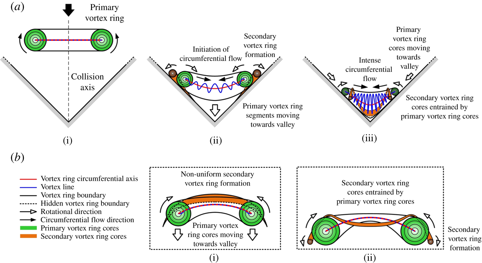
To better explain this particular flow scenario and the resulting flow behaviour, figure 18 illustrates the flow dynamics as interpreted from the flow visualization results presented earlier. Note that the vortex-ring circumferential axis and vortex-line nomenclature conform to those used by Lim (Reference Lim1989) for the sake of consistency. To begin, figure 18(a)(i) shows the primary vortex ring translating towards the valley initially but remaining sufficiently far upstream such that the presence of the V-wall does not influence its behaviour. As it collides with the V-wall subsequently, as shown in figure 18(a)(ii), vortex-ring segments impacting along the V-wall will decelerate and initiate the formation of the secondary vortex ring, while the non-impacting vortex-ring segments along the orthogonal plane continue to translate towards the valley bottom (see figure 18b(i)). Based on the earlier observations by Lim (Reference Lim1989) and New et al. (Reference New, Shi and Zang2016), the vortex line associated with the primary vortex ring will take up a bi-helical form around its circumferential axis and produce a circumferential flow from the vortex-ring segments that first collide with the inclined surfaces of the V-walls (i.e. valley plane) towards the other segments that have not collided with any part of the V-wall (i.e. orthogonal plane). In other words, earlier collisions between primary vortex-ring segments and the V-wall surfaces will produce a non-uniform secondary vortex ring. Specifically, the secondary vortex-ring formation will initiate along the V-wall surfaces before propagating towards the orthogonal plane gradually as other primary vortex-ring segments continue to translate towards the valley bottom, as depicted in figure 18(b)(i). The increasing proximity of the primary vortex-ring segments to the boundary layer closer to the valley bottom will gradually cause the latter to separate to form the rest of the secondary vortex ring.
Flow dynamics along the (a) valley and (b) orthogonal plane as interpreted from the flow visualizations.

As the collision process continues, figure 18(a)(iii) shows the entrainment of the secondary vortex-ring cores by their primary vortex-ring counterparts along the valley plane. Concurrently, the primary vortex-ring cores would have travelled further along both V-wall surfaces towards the valley bottom. This subsequently leads to comparatively more severe vortex compressions along the vortex-ring segments located along the orthogonal plane, which will account for the rapid bulging and transition to incoherence in the primary vortex-ring cores observed earlier. It should, however, be noted that the heightened compression level would also limit the extent of circumferential flows and hence vortex-stretching behaviour along vortex-ring segments that had collided with the V-wall surfaces earlier on. This in turn suggests that higher adverse pressure gradients exist along the two inclined surfaces of a V-wall, as compared to the scenario when only an inclined wall is present. As a result, the wall boundary layers will separate earlier along the V-wall inclined surfaces as compared to an equivalent inclined wall, which would then support the vortex-core trajectory behaviour. On the other hand, the formation of the secondary vortex ring would have propagated till the orthogonal plane as illustrated in figure 18(b)(ii). As the flow progresses, it is expected that increasingly more of the secondary vortex ring will be entrained by the primary vortex ring, after which the flow will become more incoherent due to the significant vortical interactions.
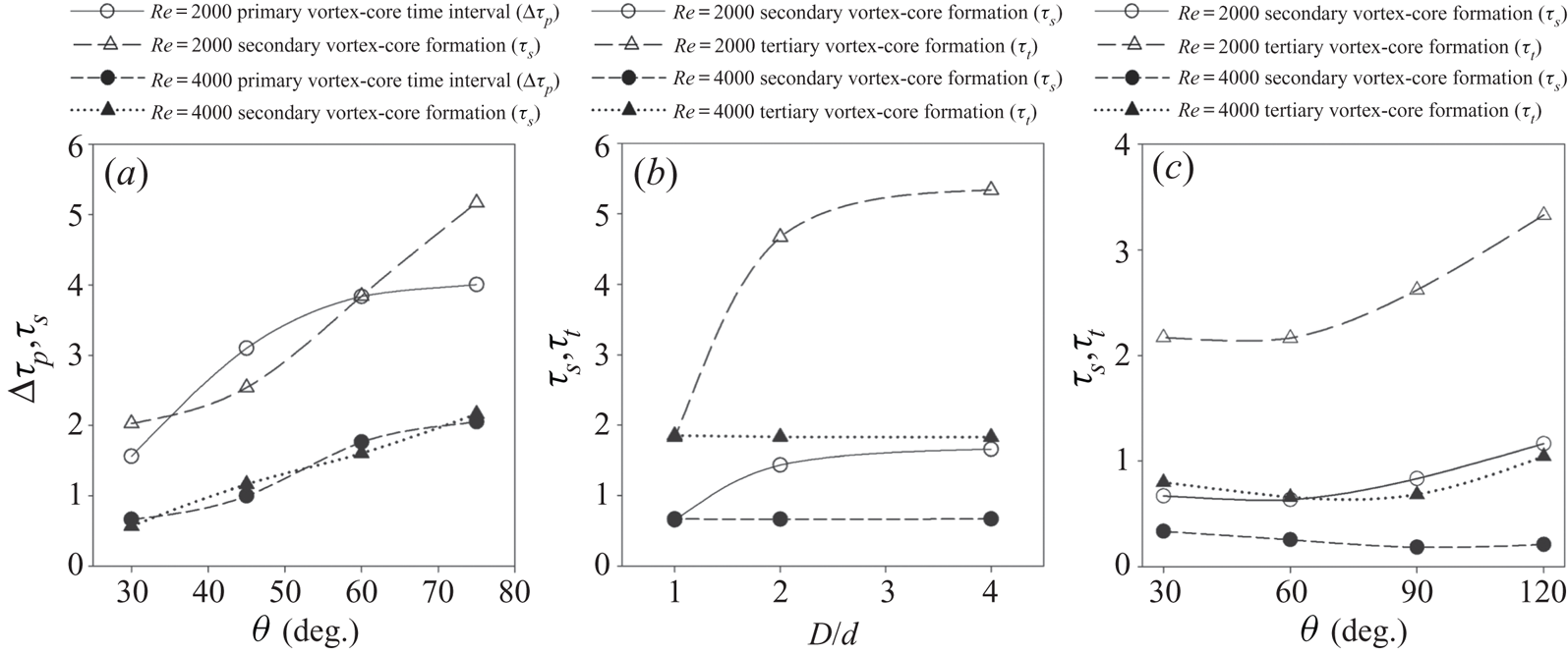
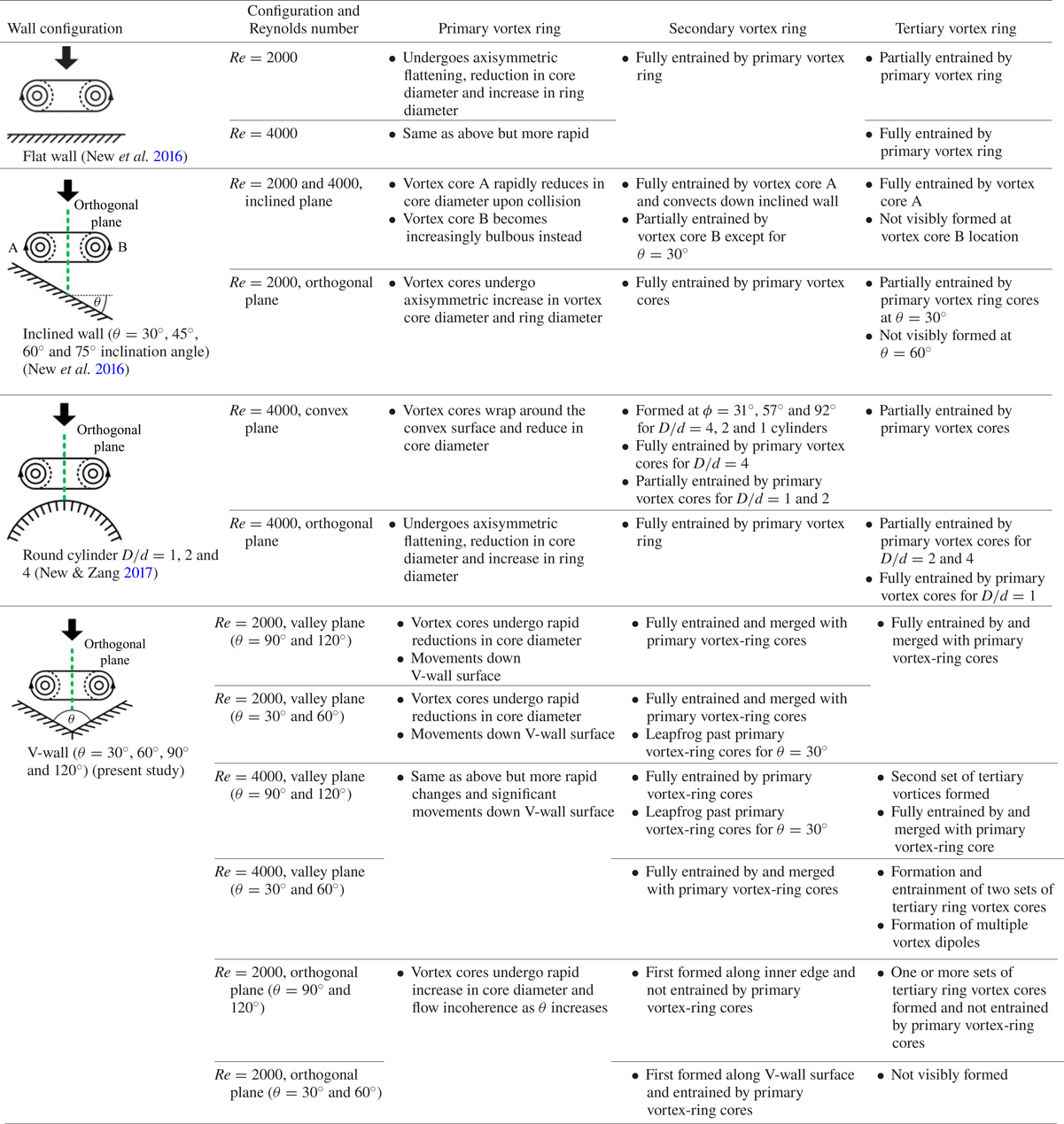
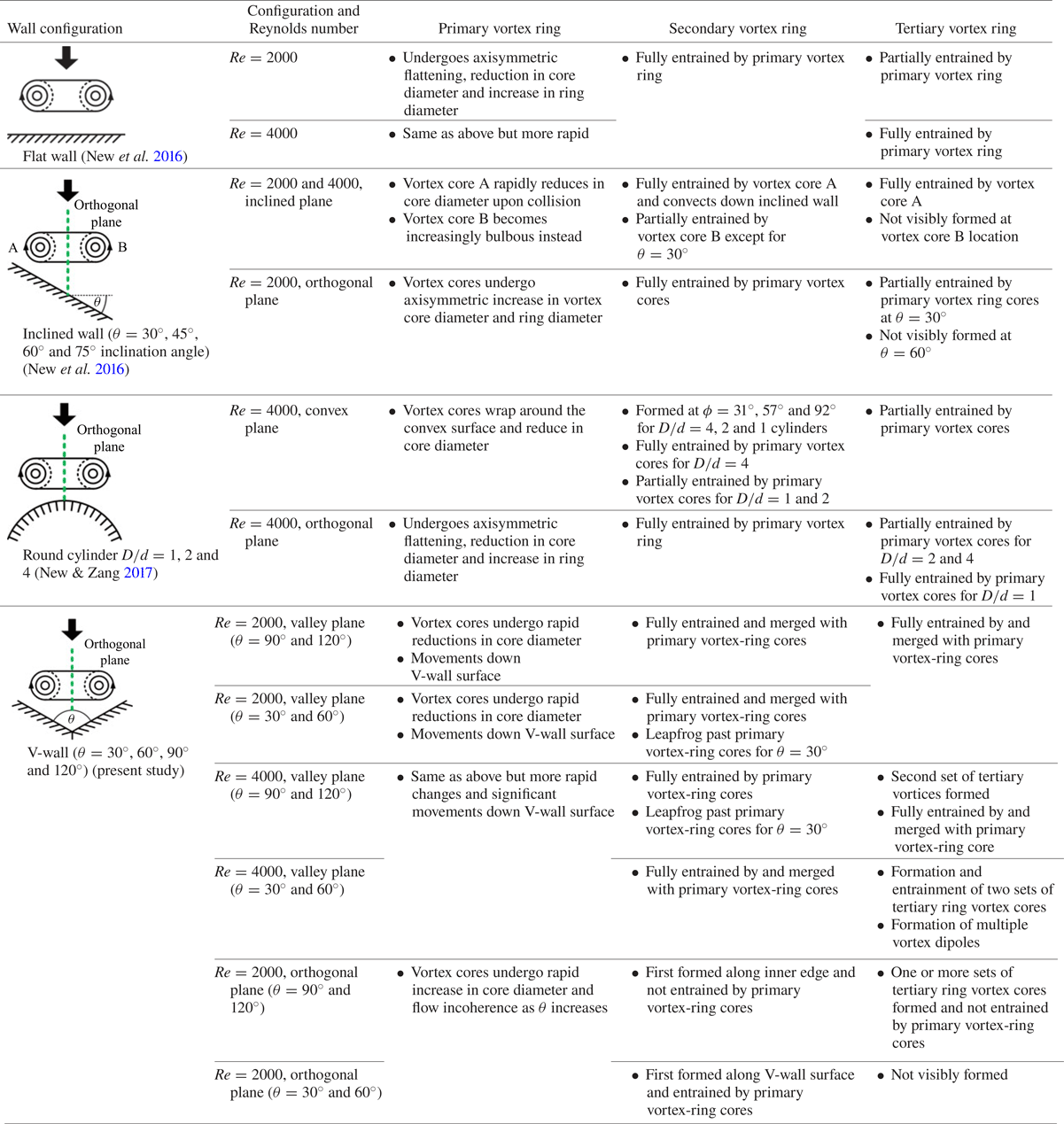
Finally, since New et al. (Reference New, Shi and Zang2016) and New & Zang (Reference New and Zang2017) conducted vortex-ring collisions with other surface configurations using quite similar equipment and experimental conditions, it will be appropriate to take stock of the impact of surface configurations upon the primary vortex-ring behaviour, the formation of secondary and tertiary vortex rings and their mutual interactions after the collisions. Table 1 shows a brief summary of all this behaviour associated with vortex-ring collisions with a flat wall, inclined walls, round cylinders and the present V-walls. Note that the accompanying figures in table 1 for the inclined wall, round cylinder and V-wall vortex-ring collisions show the inclined plane, convex plane and valley plane, respectively. The orthogonal plane is aligned into the figures and represented by the green dashed lines. It is clear from the comparisons between the different flow configurations that the outcomes from the vortex-ring collisions are highly sensitive to the boundary conditions, and it remains challenging to infer the outcome of one collision configuration based on another. Nevertheless, the availability of these observations arising from three systematic studies based on a common experimental set-up and conditions will be useful to understand more complex collision scenarios in the future. It should also be noted that not only do the different vortex-ring collision scenarios produce different vortex structures and behaviour, but also the timings at which these vortex structures formed after the collision will be of interest as well. This is particularly the case for asymmetric collision scenarios and when a systematic comparison of these timings has not been carried out previously. Since these timings are available from the two earlier studies and the present one, they were extracted from flow visualization video recordings captured at  ${Re} =2000$ and 4000 and compiled here in figure 19. Note that only timings associated with collisions along the inclination plane of inclined walls, the convex plane of round cylinders and the valley plane of V-walls will be of interest here, as they best reflect the impact of surface geometries upon vortex-ring collisions.
Comparisons of formation time lags between diametrically opposite primary/secondary vortex-ring cores for (a) inclined-wall collisions, as well as formation times of secondary/tertiary vortex-ring cores for (b) round cylinder and (c) V-wall collisions. Empty symbols are for  ${Re} =2000$, and filled symbols for
 ${Re} =4000$.

Brief summary and comparisons between vortex-ring collisions upon flat-wall, inclined-walls, round cylinders and V-walls.
As the collisions of primary vortex-ring cores A and B (see table 1) with the inclined walls, as well as the resulting formation of their respective secondary vortex-ring cores, occur at different times, the time intervals between their collisions and formation times (relative to A or B) were non-dimensionalized as before and are shown in figure 19(a). The results portray a logical trend whereby the primary vortex-core collision time interval ( $\Delta {\tau _p}$) and secondary vortex-ring formation times (
 $\tau _s$) become increasingly larger as the inclination angle increases, regardless of the exact Reynolds number. However, it is interesting to note that, at
 ${Re} =2000$ here, the rate at which
 $\Delta {\tau _p}$ increases slows down while that of
 $\tau _s$ increases further as the inclination angle increases. As the Reynolds number doubled from
 ${Re} =2000$ to 4000, the collision time intervals and formation times decrease drastically.
However, that should not come as a surprise, as table 1 has already provided indications that flow transitions will be more rapid at higher Reynolds numbers. Nevertheless,  $\Delta {\tau _p}$ and
 $\tau _s$ increase in more linear-like manner at
 ${Re} =4000$ here. This also suggests that the collision times become less dependent on the exact Reynolds number and more directly upon the inclination angle, once a threshold Reynolds number is exceeded. The differences in the behaviour observed at the two different Reynolds numbers are likely to be due to the greater discrepancies in the nonlinear vortex-stretching/compression behaviour for vortex cores A and B.
Intriguingly, figure 19(b) shows that round-cylinder-based collisions demonstrate more consistent trends when it comes to secondary and tertiary vortex-ring core formation times ( $\tau _t$) at each Reynolds number used. For instance,
 $\tau _s$ and
 $\tau _t$ undergo significant increments before plateauing as the diameter ratio increases from
 $D/d=1$ to 4 at
 ${Re} =2000$. Furthermore,
 $\tau _s$ and
 $\tau _t$ remain practically flat across all diameter ratios at
 ${Re} =4000$. In contrast, inclined-wall and V-wall collisions produce less consistent trends at the same corresponding Reynolds numbers. In particular, note that flat-wall-based (i.e. assumed as
 $D/d\rightarrow \infty$) collision leads to approximately
 $\tau _s=1.815$ and
 $\tau _t=5.150$ at
 ${Re} =2000$ and approximately
 $\tau _s=0.665$ and
 $\tau _t=1.670$ at
 ${Re} =4000$, which are close to the values observed for
 $D/d=4$ at the same Reynolds number (i.e.
 $\tau _s=1.660$ and
 $\tau _t=5.340$ at
 ${Re} =2000$, and
 $\tau _s=0.670$ and
 $\tau _t=1.830$ at
 ${Re} =4000$). Hence, this significantly strengthens the notion that round-cylinder-based collisions increasingly resemble flat-wall-based collisions when the diameter ratio increases (New & Zang Reference New and Zang2017).
Last, but not least, V-wall-based collision results are shown in figure 19(c), where  $\tau _s$ and
 $\tau _t$ can be observed to increase with the included angle. It should also be highlighted that the rate of increase grows as the included angle increases, at least for
 ${Re} =2000$. In fact, note that
 $\tau _s=1.165$ and
 $\tau _t=3.330$ at
 ${Re} =2000$, and
 $\tau _s=0.210$ and
 $\tau _t=1.045$ at
 ${Re} =4000$, for the
 $\theta =120^{\circ }$ V-wall, which are approaching those for flat-wall-based (i.e.
 $\theta =180^{\circ }$) collisions. Interestingly, though, both
 $\tau _s$ and
 $\tau _t$ appear to decrease initially as the included angle increases from
 $\theta =30^{\circ }$ to 90
 $^{\circ }$, before they increase at
 $\theta =120^{\circ }$ for
 ${Re} =4000$.
Interestingly, round-cylinder-based collisions demonstrate more consistent correlations between the diameter ratio and the secondary/tertiary vortex-ring core formation times, followed by V-wall-based collisions and then inclined-wall-based collisions, at least for the range of physical configurations, vortex-ring conditions and Reynolds numbers used here. While this is surprising at the first instance since inclined walls are physically closest to flat walls, it may be better appreciated if one considers that inclined-wall collisions are asymmetrical while round-cylinder- and V-wall-based collisions are not. For symmetrical surface geometries, the primary effects of the surface configuration (i.e. round or V-shaped) are expected to be in terms of vortex-stretching/compression effects conferred upon the various vortex-ring structures after the collisions, which occur symmetrically about the collision axis in flat-wall, round-cylinder and V-wall configurations. In contrast, vortex rings colliding with inclined walls are subjected to asymmetrical vortex stretching/compression and secondary/tertiary vortex-ring formation, which would have led to highly asymmetrical and more complex three-dimensional mutual interactions between the primary, secondary and tertiary vortex rings. As such, the correlation between the inclination angle and primary/secondary vortex-ring collision times could conceivably be weaker than those for round-cylinder- and V-wall-based collisions.
4. Conclusion
Collisions between circular vortex rings and V-walls were studied experimentally using LIF and TR-PIV techniques. Results show that, while there exist some similarities between the present scenario and that associated with vortex-ring collisions upon flat inclined walls, additional physical constraints imposed by the V-walls lead to more complex three-dimensional vortical changes. For instance, the formation of secondary and tertiary vortex-ring segments along the orthogonal plane lag behind those along the valley plane (i.e. V-wall surfaces), since the primary vortex ring collides with the latter earlier. Primary, secondary and tertiary ring core sizes are observed to undergo significant reductions, which become progressively more rapid as the included angle reduces. Additionally, using a higher-Reynolds-number vortex ring and/or smaller included angle will result in secondary and tertiary vortex-ring cores leapfrogging past the primary vortex-ring cores along the V-wall surfaces after their entrainment. This introduces adverse pressure gradients and produces wall-separated vortices upstream of the primary vortex-ring cores, the former of which pair up with the secondary and tertiary vortex-ring cores to form series of daisy-chained vortex dipoles. Along the orthogonal plane, however, the primary vortex-ring cores become increasingly bulbous and incoherent as the flow progresses. Secondary vortex-ring cores are also observed along this plane at later times as well, when the secondary vortex-ring formation eventually propagates towards this plane. Interactions between the primary and secondary vortex rings further give rise to additional vortex structures observed and movements of the former away from the collision axis along this plane.
Circulations of the primary, secondary and tertiary vortex-ring cores determined from the TR-PIV measurements provide support for the notion that the flow behaviour for  $\theta =30^{\circ }$ to 60
 $^{\circ }$ V-walls differs from that associated with
 $\theta =90^{\circ }$ to 120
 $^{\circ }$ V-walls. In particular, momentary increases in the primary vortex-ring core circulations along the orthogonal plane are observed only for the latter configurations after they have been drastically reduced from the collisions. In addition, secondary vortex-ring core circulations tend to increase after they are formed along this plane, in contrast to the scenario along the valley plane, where they tend to decrease instead. Along the valley plane, primary vortex-ring circulation decreases discernibly earlier for smaller included angles, alongside a more gradual reduction incurred after the V-wall collisions. Vortex-core trajectory observations show slightly earlier secondary vortex-core formations in V-walls over inclined walls of equivalent inclinations as well. The preceding observations can be accounted for by the bi-helical vortex line flow model proposed by Lim (Reference Lim1989) for vortex-ring collisions upon single inclined walls. Unlike an inclined wall, however, V-walls possess two inclined surfaces facing towards each other about a symmetrical plane with a physically constrained valley where they meet at the vertex. As such, collision of each primary vortex-ring core upon each inclined surface of every V-wall will cause the former vortex line to transit into bi-helical mode, thus driving circumferential flows from the collided vortex-ring segments along the valley plane towards those along the orthogonal plane. To illustrate this, a flow model is provided here to highlight the general behaviour of and interactions between primary and secondary vortex rings after the collisions.
Last but not least, a comparison between vortex-ring collisions upon flat walls, inclined walls, round cylinders and the present V-walls conducted under similar experimental conditions by the authors previously is carried out to provide a more systematic overview on the range of collision behaviour and vortical outcomes. Furthermore, temporal information on the different primary vortex-ring core collision times, and secondary and tertiary vortex-ring core formation times are extracted from the earlier and present studies to quantify the effects of Reynolds number, inclination angle, round cylinder diameter ratio and V-wall included angle. The comparison shows that round-cylinder- and V-wall-based collisions produce non-dimensionalized collision times that converge towards flat-wall-based collisions more consistently when the diameter ratio and included angle become progressively larger, respectively. Interestingly, this appears to be less consistent for inclined-wall-based collisions, presumably due to the asymmetrical formations of and interactions between various asymmetric vortex-ring structures.
Acknowledgements
The authors acknowledge the support for the study by the School of Mechanical and Aerospace Engineering, Nanyang Technological University, Singapore, Singapore Ministry of Education AcRF Tier-2 grant (MOE2014-T2-1-002) and National Science Foundation of China grant (grant number: 11772197).
Declaration of interests
The authors report no conflict of interest.
Supplementary movies
Supplementary movies are available at https://doi.org/10.1017/jfm.2020.425.