
I. INTRODUCTION
The rapid increasing demand for multifunctional and miniaturized communication devices results in a need for further integration and high density package of electronic components. This is especially true for antenna, since its size is an important factor, which determines the overall size of mobile devices.
Reference Kong, Li, Liu, Huang, Abshinova, Yang, Tang, Tan, Deng and Matitsine1
The length of the electromagnetic wave is influenced by the permittivity and permeability of the substrate materials (
 $\lambda = {{{\lambda _0}} \over {\sqrt {\varepsilon '\mu '} }}$
, where λ and λ0 are the wave length in the material and in vacuum, ε′ and μ′ are the relative permittivity and permeability of the material). Hence, the magneto-dielectric composite is desired as the substrate materials in the miniaturization design of antennas. Usually, the magnetic-dielectric composite possesses much higher permittivity than the permeability, which is not suitable to be used as the antenna substrate materials.
Reference Yan, Zhen, Xu, Jiang, Shao and Tang2,Reference Lee, Hong, Bae, Jalli, Abo, Park, Seong, Park and Ahn3
That may lead to very high parasitic capacitance in device, as well as the mismatch of the antenna impedance to free space environment (
 $Z = {Z_0}\sqrt {{{\mu '} \over {\varepsilon '}}}$
, where Z and Z
0 are impedances of the materials and free space). This problem can be solved better by using the materials with almost equal values of relative permittivity and permeability, which are rarely found in nature. So the composite with the combination of high and almost equal permittivity and permeability as well as low-loss tangent is very necessary.
Reference Keun, Ki, Sig, Hoon, Ho and Mo4–Reference Thakur, Chevalier, Mattei and Queffelec6
Generally speaking, the ceramic-based composite always shows higher magnetic and dielectric loss than the polymer-based composite. And in most cases, composite with high permittivity is much easier to achieve than that with high permeability, which caused by the higher conductivity magnetic materials especially the metal alloys.
Reference Shirakata, Hidaka, Ishitsuka, Teramoto and Ohmi7
Thus the ferrite-polymer composite is always selected for the preparation of this kind of composite.
The physical and chemical properties of ultrafine particles on the nanoscale and microscale strongly depend on their size, shape and crystallinity, including electrical, magnetic, optical, and other related properties. Reference Fu, Jiang, Xu and Zhen8,Reference Bellucci, Lobato de Almeida, Lima Nobre, Angel Rodriguez-Perez, Paschoalini and Job9 The ferrite powders synthesized through solid-state reaction method have many microdefects, such as microcracks, pores, and lattice imperfections etc., which can seriously affect the magnetic properties of the composite. Therefore, the annealing treatment, which could modify the defects and stress in the ferrite grains, is used to improve the magnetic properties of the composite materials. Reference Wen, Liu and Zhao10
In this work, we chose a common Ni0.5Zn0.5Fe2O4 (NZO) ferrite and present an effective and simple method to improve the crystallinity and the micromorphology of the ferrite powders through annealing treatment. Poly(vinylidene fluoride) (PVDF) is a semicrystalline polymer with excellent piezoelectric and dielectric properties among polymers. These properties combined with its high elasticity, plasticity, and easy processing make this material suitable for numerous technological applications. Reference Guo, Liu, Wang, Withers, Chen, Jin and Smith11,Reference Martins, Costa, Botelho, Lanceros-Mendez, Barandiaran and Gutierrez12 The annealed NZO powders (at 700, 900, 1100 °C) and the derived NZO/PVDF composites were synthesized and characterized. Effects of the annealing treatment on the dielectric-magnetic properties of the powders and the NZO/PVDF composites were investigated. The relationship between the microstructures and properties were discussed.
II. EXPERIMENTAL
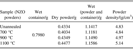
NZO powders were synthesized via the solid-state reaction method. Reagent-grade NiO (>99%), ZnO (>99%), and Fe2O3 (>99%) were mixed thoroughly and calcined at 1000 °C in air for 2 h to form spinel-phase NZO powders. Then the crushed NZO powders were milled in a ball mill, where the mass ratio of zirconia ball and ferrite powder is 3:1. The obtained ultrafine powders were annealed at the different temperatures of 700 °C, 900 °C, and 1100 °C for 3 h, respectively. The densities of the powders before and after annealing treatment were measured by the Archimedean method, while a small container was added into the density measuring equipment. The densities of the annealed powder can be calculated by the following equation:
 $${\rho _{{\rm{powder}}}} = {{{d_{\rm{p}}}} \over {{w_{\rm{c}}} + {d_{\rm{p}}} - {w_{{\rm{cp}}}}}}\quad ,$$
where d p is the quality of the NZO powders measured in air, w c, and w cp denote the mass of the container and the mass sum of the container and powders, which are measured in the water. The measured and calculated results are shown in Table I.
The measuring results of the powder density.

NZO powders were characterized by x-ray powder diffraction (XRD) recorded in the range from 2θ = 15–70° using an x-ray diffractometer (D/MAX-2400, Rigaku Corporation, Tokyo, Japan) with Cu Kα radiation. The crystallite size of the samples were calculated from the most intense peak (311) using the Debye–Scherrer formula. The micromorphology of the NZO powders were studied with a scanning electron microscope (SEM; Quanta F250, FEI Company, Hillsboro, Oregon) and a specific surface area and porosity analyzer (ASAP 2020, Micromeritics, Norcross, Georgia). The magnetic hysteresis loops of the NZO powders were measured by vibrating sample magnetometer (VSM-7410; Lake Shore, Westerville, Ohio).
The PVDF was used as the dielectric matrix to make magnetic-dielectric composite with the NZO powders (the powder after ball mill, annealed at 700 °C, 900 °C, 1100 °C) and the corresponding samples are named S1 to S4, respectively. They were fully mixed together with a volume fraction of 50%. The mixture was molded into discs (d = 15 mm, h = 1 mm) and rings (d out = 15 mm, d in = 9 mm, h = 1 mm) by hot pressing at about 200 °C and 20 MPa for 5 min. The dielectric properties of the ceramic in the low-frequency range (100 Hz–1 MHz) were measured by an impedance analyzer (4980, Agilent, Palo Alto, California). The magnetic and dielectric measurements of the composite in higher frequency range of 1 MHz–1 GHz were carried out by an impedance analyzer (4291B Agilent) with a 16454L magnetic material test fixture and a 16453A dielectric material test fixture, respectively.
III. RESULTS AND DISCUSSION
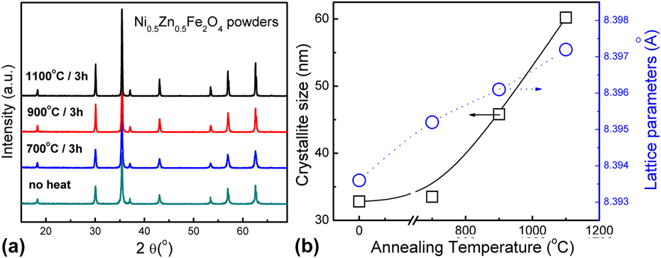
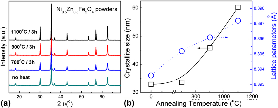
The x-ray diffraction patterns of the NZO powders are shown in Fig. 1(a). It reveals the effect of annealing on the crystallinity of the NZO particles. All the peaks of the samples can be clearly indexed to the eight major peaks of the spinel ferrites, which are (111), (220), (311), (222), (400), (422), (511), and (440) planes of cubic unit cell. The intensities are obviously enhanced through annealing, which indicates the improvement of annealing treatment on the crystallinity of the NZO powders. The average crystallite size of the samples was calculated from the most intense (311) peak using the well-known Debye Scherrer equation: D = 0.94λ/(β·cos θ), where D is the average crystallite size, λ is the wave length of x-ray, β is the full width half maximum, and θ is the angle of diffraction. The crystallite size of the samples is presented in Fig. 1(b). It is seen that with the annealing temperature increase, the crystallite size of the samples lies in nanocrystalline range and increases, similar variation has been reported in the sintered spinel ferrites. Reference Azhagushanmugam, Suriyanarayanan and Jayaprakash13,Reference Zheng, Zhang, Xiao, Yang and Jia14 While the lattice constant also increases slightly at the same time. The densities of the NZO powders are shown in Table I. It can be seen that the powder density increases with the annealing temperature, which is due to the fact that the crystallinity has been improved in the annealing process.
(a) XRD patterns of the NZO powders and (b) the calculated crystallite size and lattice parameters of the powder samples.
The microphotographs of the powder samples are shown in Fig. 2. The milled powder is composed of angular grains with rough grain surface. The details from the insets of Figs. 2(a)–2(c) show that in the ball mill process, the starting powders were subjected to the repeated cracking and their surface lattices have been significantly broken, and thus the microcrack can be observed clearly on the surface of the fine powders. The grain size remains unchanged compared to the starting powders when the annealing temperature is at 700 and 900 °C. However, the grains become larger (1 µm) and show more spherical morphological grains after the annealing treatment at 1100 °C. The spiral growth steps on the NZO grains indicating the annealing process can promote the development and crystallinity of the ferrite grains [Fig. 2(d)].
SEM micrographs of the NZO powder samples: (a) unannealed, (b) 700 °C, (c) 900 °C, and (d) 1100 °C.

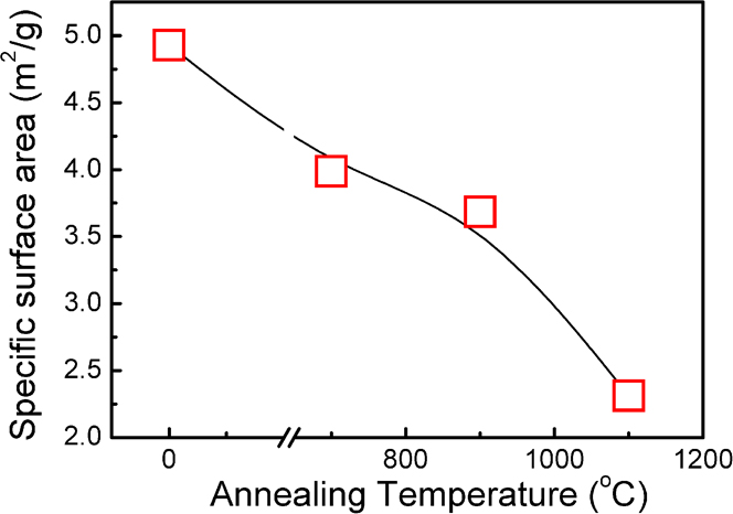
The measuring result of specific surface area of the NZO powders is shown in Fig. 3. It can be seen that the specific surface area value decreases sharply with the increase of the annealing temperature. It drops from 4.93 to 3.99 m2/g after being annealed for 3 h at 700 °C and further decrease to 2.31 m2/g when the annealing temperature rises up to 1100 °C. The decrease of the specific surface area is mainly due to the grain crystallize and development in the annealing treatment, which lead to the reduction of the microdefects, such as the microcracks, pores, lattice defects etc., caused by the milling process.
Variation of the specific surface area values of the NZO powders samples.

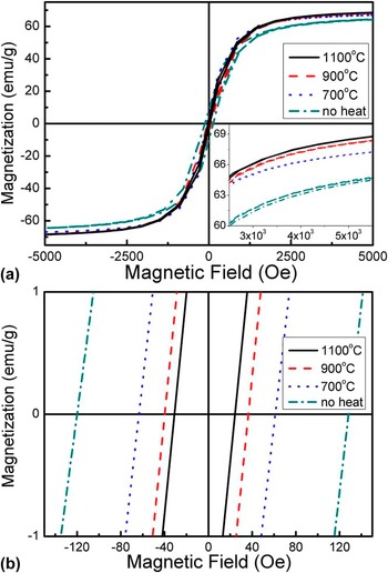
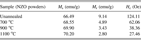
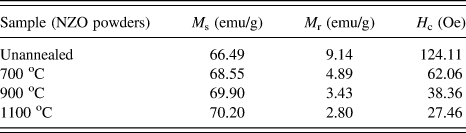
Figure 4 shows the magnetic hysteresis loops in the magnetic field range of (a) −5000 to 5000 Oe, and (b) −150 to 150 Oe of the NZO powders annealed at different temperatures, the relative magnetic parameters are shown in Table II. It is obvious that the coercivity (H c) decreases with increase of annealing temperature. It is reported that the H c value can be influenced by the microstress and defects of the ferrite grains and proportional to the stress value. Reference Zou, Yu and Bain15,Reference Staunton, Szunyogh, Buruzs, Gyorffy, Ostanin and Udvardi16 This kind of microscopic stress can result from the microcrack and defects that formed under the external force in the ball milling process. The research result on the high energy ball milling shows the microstress and the average strain of fine powder gains with the increasing ball milling time. Reference Moyet, Cardona, Vargas, Silva and Uwakweh17,Reference Abdoli, Ghanbari and Baghshahi18 Consequently, the reduction of the H c value can be attributed to the annealing process, which decreases the microstress derived from the defects. Meanwhile, the saturation magnetization (M s) increases slightly as expected, since it depends mainly upon the movement of magnetic domain walls, which are influenced much by the measuring temperature. Reference Staunton, Szunyogh, Buruzs, Gyorffy, Ostanin and Udvardi16,Reference Fang, Wang, Zhang and Mao19
Magnetic hysteresis loops in the magnetic field range of (a) −5000 to 5000 Oe and (b) −150 to 150 Oe of the NZO powders.

Magnetic parameters of NZO powders annealed at different temperatures.
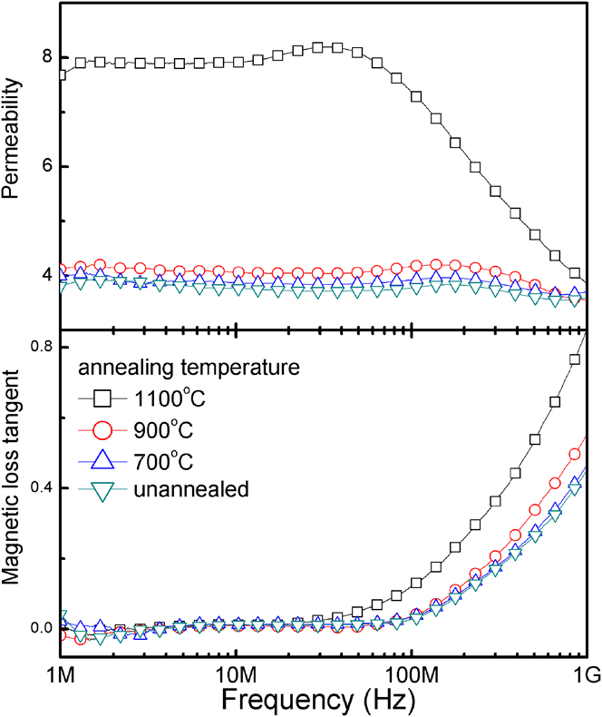
The frequency dependence of the magnetic properties of the NZO/PVDF composite is shown in Fig. 5. Generally, for the ferrite materials, some different factors will influence the permeability simultaneously. These are the intrinsic factors such as saturation magnetization, magnetostriction, and anisotropy as well as the extrinsic factors such as microstructure, grain size, porosity, stress, etc. It can be seen that the initial permeability and magnetic loss increase with the increasing of annealing temperature. Especially, the sample S4, has much larger initial permeability. This mainly attributed to two aspects caused by the annealing treatment, one is the growth of the grain size and the other one is the improvement of the microstructure. In the sintered Ni–Zn ferrite, the permeability increases with increasing grain size, following the relation μ ∝ D 1/3, where D is the diameter of a grain. Reference Igarashi and Okazaki20 In the previous works, it has been proved that ferrite with larger grain size shows higher initial permeability. Reference Clausell, Barba, Nuno and Jarque21–Reference Deka and Joy23 Moreover, the increasing annealing temperature always leads to decreasing magnetic anisotropy thereby reducing the internal stresses and crystal anisotropy, which will result in minimum hindrance required for movement of the domain walls. Reference Deka and Joy23,Reference Sakellari, Tsakaloudi, Polychroniadis and Zaspalis24 Therefore, the initial permeability increases with the increase of annealing temperature.
Complex permeability of the NZO/PVDF composite samples in the frequency range of 1 MHz–1 GHz.

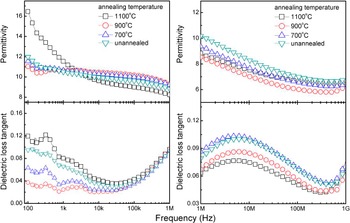
Figure 6 shows the frequency dependence of the dielectric properties of the NZO/PVDF composite in a wide frequency range from 100 Hz to 1 GHz. At low frequency (<1 kHz), the sample S4 shows much higher permittivity than other samples. Based on Koops' theory, Larsen and Metselaar derived a formula to estimate the static permittivity value (εs) of the polycrystalline yttrium iron garnet ferrites: εs = εi(d
1 + d
2)/d
1, where d
1 is the thickness of lower conductivity layers, d
2 is the thickness of well-conducting grains, and εi is the relative permittivity at infinite frequency.
Reference Zheng, Zhang, Xiao, Yang and Jia14,Reference Larsen and Metsleaa25
Here, we can take the permittivity at 100 Hz and 1 GHz as εs and εi, respectively, and assume that d
1 does not change significantly. In this case, the thickness of grains d
2 can be written as follows:
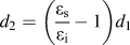 ${d_2} = \left( {{{{\varepsilon _{\rm{s}}}} \over {{\varepsilon _{\rm{i}}}}} - 1} \right){d_1}$
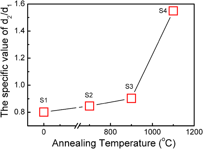
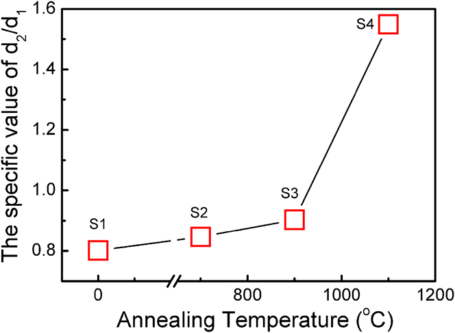
. We can qualitatively plot the variation of d
2/d
1 for all the samples, as shown in Fig. 7. Obviously, the sample S4 shows a large value of d
2/d
1, indicating that the grain size increases significantly after 1100 °C annealing treatment. This result is in full agreement with the results observed in the SEM images. The permittivity shows good stability from 10 MHz to 1 GHz. The loss peak at about 10 MHz is caused by the dielectric properties of PVDF, which is the polymer matrix of the composite.
Reference Dang, Wang, Peng and Nan26
Complex permittivity of the NZO/PVDF composite samples in the frequency range of 100 Hz–1 GHz.

The variation of the calculated d 2/d 1 for the samples.
As mentioned in the introduction, reduction of the antenna size has always been a challenge to the designer. However, with the development in material technology, small antennas can be realized via smart design upon new material properties. Reference Kong, Li, Lin and Gan27 In the previous works, ceramic composites are researched for antenna miniaturization. The reported material shows enhanced miniaturization factors, reduced loss tangent value without compromising performance. Reference Su, Chang, Wang, Sokolov, Hu, Chen and Harris28
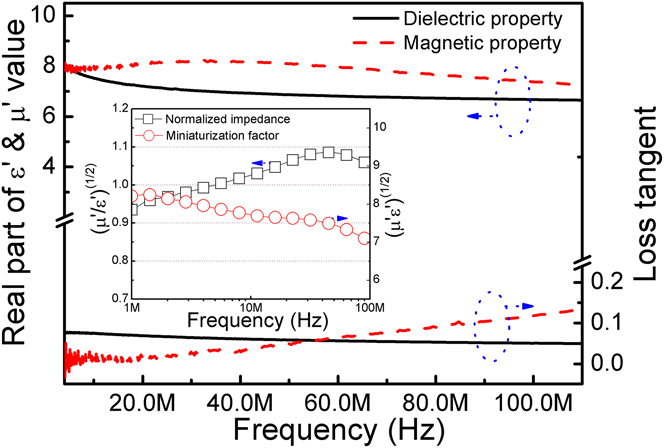
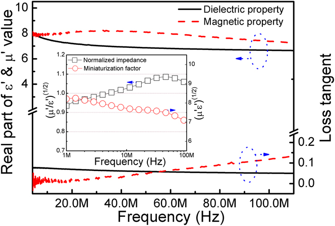
The magnetic and dielectric properties, normalized impedance (μ′/ε′)1/2, and miniaturization factors (μ′ε′)1/2 of the composite made by the composite sample S4 are shown in Fig. 8. It is obvious that the almost equal value of μ′ and ε′ are obtained in the test frequency range from 10 to 100 MHz. Moreover, the impedance value is normalized from 1 MHz to several hundred MHz, which means that the characteristic impedance is almost equal to the impedance of free space in wide frequency range. A large miniaturization factor of about 8 is achieved. These data show desirable characteristics for magneto-dielectric antenna substrate materials in high frequency bands (VHF, 30–300 MHz). It is necessary to mention that low magnetic and dielectric loss tangents are critical for materials used in antenna designs. It could be observed that the dielectric loss is extremely low within the whole studied frequency range, and the magnetic loss remains very low within 60 MHz. Although the magnetic loss of the composite still seems high for practical applications, they can be effectively reduced by substitution and surface modification methods, Reference Fawzi, Sheikh and Mathe29,Reference Yadav, Shinde, Kadam and Rajpure30 and these methods can also help to reduce the dielectric loss by improving the resistivity of the fillers. Reference Berthelot, Basly, Buffiere, Majimel, Chevallier, Weibel, Veillere, Etienne, Chung, Goglio, Maglione, Estournes, Mornet and Elissalde31,Reference Iqbal, Islam, Ali, Khan, Sadiq and Ali32 Furthermore, the dielectric loss of PVDF is not low in the polymer materials, thus using low-loss host matrix, the epoxy resin for example, is another practical approach to decrease the dielectric loss tangent of the composites. Reference Chen, Chang, Hsiang, Hsu and Yen33,Reference Souriou, Mattei, Chevalier and Queffelec34
The magneto-dielectric properties of the composite sample S4.
IV. CONCLUSIONS
NZO powders after ball milling are annealed at different temperatures and dispersed into PVDF polymer matrix with a volume fraction of 50% to obtain a series of NZO/PVDF composite materials. The properties of both the NZO powders and the NZO/PVDF composite materials are characterized.
For the ferrite powder synthesized by the solid-state reaction method, the annealing process is necessary to improve its crystallinity and microdefects, which can lead to a significant improvement in the magneto-dielectric properties. Such magneto-dielectric composite with high and almost equal permeability and permittivity could be a promising candidate for the antenna substrate materials with reduced physical dimension and good impedance matching to free space.
ACKNOWLEDGMENTS
This work is supported by National Natural Science Foundation of China (Grant No. 51602256), and the Scientific Research Starting Foundation, Xi'an University of Technology.