
I. INTRODUCTION
The functionally graded shape memory alloy (FG-SMA) is a new kind of functional composite, which holds the particular properties of both functionally graded materials (FGMs) and shape memory alloys (SMAs). According to the components and structures of this material, FG-SMA can be divided into two categories: one is after special procedures, the SMA whose microstructure varies gradually and thus the macroproperties vary gradually, so as to create the FG-SMAReference Birnbaum, Satoh and Yao1,Reference Mahmud, Liu and Nam2 ; the other is composed of SMA and other materials (such as ceramic and so on), and the component ratio varies gradually, thus producing the FG-SMA.Reference Burkes and Moore3–Reference Xue, Dui and Liu6 Such as NiTi–TiC FG-SMA, the NiTi SMA can reduce the maximum stress, satisfying the needs of large deformation; while the TiC has high strength and wear resistance. The FG-SMA composed of these two materials has both the phase transformation characteristics of SMA at one side and the abrasion resistant properties of TiC at another side. Furthermore, the material failure caused by stress concentration can be relieved due to the gradient variation of the component materials.
As the growing demand in high and new technology applications, a deep understanding of the mechanical properties of the FG-SMA is required, and several literature studies which investigate the properties of this new functional composite have been published recently. Birnbaum provided a novel mechanism and process that can control the shape memory response spatially within monolithic NiTi thin film structures.Reference Birnbaum, Satoh and Yao1 This technique can effectively control the temperature of martensitic phase transformation and thus control the mechanical and shape memory responses as well. Mahmud introduced a new heat treatment approach which can create the functionally graded near-equiatomic NiTi SMA.Reference Mahmud, Liu and Nam2 In this approach, SMA is annealed with a graded temperature after cold work, and thus create a graded structure in the matrix of SMA. Tian reported a novel “hot” target method to produce functionally graded or layered materials.Reference Tian and Schryvers4 Cole developed an approach by depositing Ni47Ti53 films with varying thicknesses onto Ni56Ti44 substrates and annealing the films to fabricate compositional gradients by means of diffusion modification.Reference Cole, Bruck and Roytburd5 Nanoindentation measurements were adopted in this approach to detect the mechanical properties at various depths into the film. However, the existing investigations all concentrate on the fabrication and property test of FG-SMA, there is still not a reliable constitutive model or method which can describe the mechanical properties of this new material. Therefore, in-depth research is still necessary to display and predict the mechanical behavior of FG-SMAs.
Finite element model (FEM) is an efficient and commonly used calculation method, which was developed in 1940s and 1950s. With the rapid development of computer technology, the application scope and level of FEM have been greatly expanded and improved, and it has become an important approach of scientific research and engineering analysis.Reference Su, Fan and Shao7,Reference Liu, Wang, Zeng and Shang8 The existing literature studies investigating FGM with FEM all adopt the layered approach and assumed that the macroproperties vary with a power or exponential function. However, since the material properties of FG-SMA vary not only with the gradient direction but also with the variation of stress and temperature during the loading process, the existing method cannot simulate the mechanical behavior of FG-SMA very well.
In this work, a macroconstitutive model which can describe and predict the thermal mechanical behavior of an FG-SMA cylinder under pressure and graded temperature loads is provided. In this macroconstitutive model, a new concept of conical surface assumption, instead of the plane section hypothesis, is used to consider the axial deformation, and it is more nearing to reality. Besides, according to the structure features of the FG-SMA cylinder, a new layered FEM which can avoid the direct assumption of the macroproperties of the cylinder is given out. Using these two models, the thermal mechanical behavior of an FG-SMA cylinder subjected to different surface pressure and temperature loads is investigated. The characteristics of the stress distribution in the FG-SMA cylinder are discussed through numerical results. The FG-SMA cylinder discussed in this work is composed of material A and SMA, and the volume fraction of SMA in the cylinder along the radial direction is described by a power function. For non-FG-SMA, such as the common ceramic-SMA composite, it cannot reach the application purpose to resist the high temperature and play the particular properties of SMA simultaneously; the common ceramic-SMA laminated cylinder will break down easily during the pressure and temperature varying process due to the stress singularity, while the FG-SMA cylinder can achieve this application purpose and eliminate the stress singularity at the same time. This work can not only display the thermal mechanical behavior of the FG-SMA cylinder under pressure and graded temperature loads but also provide a base for the in-depth study of this kind of material.
II. THEORETICAL ANALYSIS
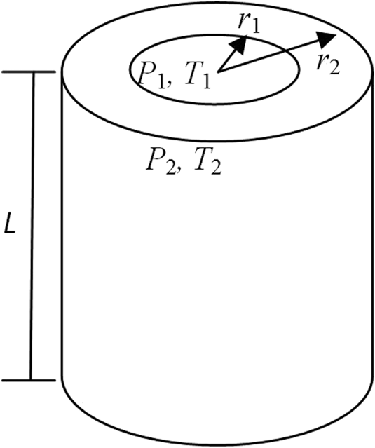
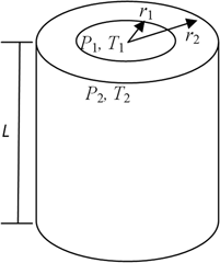
An FG-SMA cylinder consists of elastic material A and SMA subjected to inner and outer pressure and temperature loads is considered here, as shown in Fig. 1. The composition varies from material A at the inner layer of the cylinder to SMA at the outer layer of the cylinder, and the volume fraction of SMA f(r) follows a power function of radial coordinate r: f(r) = [(r − r 1)/(r 2 − r 1)]n, where r 1 and r 2 are the inner diameter and outer diameter of the cylinder, respectively, and n is the power exponent. The initial temperature of the FG-SMA cylinder is T 0. At some time, the FG-SMA cylinder is subjected to two different surface temperatures: T 1 at the inner surface of the cylinder and T 2 at the outer surface of the cylinder. Besides, the inner and outer surfaces are subjected to two different pressures: P 1 and P 2, respectively. After a sufficiently long time, a stable graded temperature field will appear in the cylinder. Owing to the pressure loads and the temperature change, the FG-SMA cylinder will go through a deformation process and a stress field will appear in the cylinder. With the purpose of studying the thermal mechanical behavior of the FG-SMA cylinder in detail, the graded temperature field is needed to be determined first.
Sketch of the FG-SMA cylinder.

A. Graded temperature field
On the basis of the heat conduction theory, the one dimensional steady-state heat conduction equation in this work can be written as
 $${{\rm{d}} \over {{\rm{d}}r}}\left[ {k\left( r \right){{{\rm{d}}T\left( r \right)} \over {{\rm{d}}r}}} \right] = 0\quad ,$$
where T(r) is the temperature in the FG-SMA cylinder. k(r) is the thermal conductivity of the cylinder and can be calculated using the mixing rule as
 $$k\left( r \right) = {k_0} + \left( {{k_1} - {k_0}} \right)f\left( r \right)\quad ,$$
where k 0 is the thermal conductivity of material A. Many articles have reported that the difference between the thermal conductivities of martensite and austenite of SMA is very small,9,Reference Huang, Leary, Ataalla, Probst and Subic10 so, here they are assumed to be equal to simplify the problem and denoted as k 1 (k 1 ≠ k 0). The analytical solution of Eq. (1) is
 $$T\left( r \right) = {{{C_1}\left( {{r_2} - {r_1}} \right)} \over {{k_0}{{\left( {{{{k_1} - {k_0}} \over {{k_0}}}} \right)}^{{1 \over n}}}}} \cdot \int {{1 \over {1 + {R^n}}}} {\rm{d}}R\quad ,$$
where
 $$R = {\left( {{{{k_1} - {k_0}} \over {{k_0}}}} \right)^{{1 \over n}}} \cdot {r \over {{r_2} - {r_1}}}\quad ,$$
 $$\int {{1 \over {1 + {R^n}}}} {\rm{d}}R = \left\{ {\matrix{ \matrix{ - {2 \over n}\sum\limits_{i = 0}^{{n \over 2} - 1} {{P_i}\cos \left( {{{2i + 1} \over n}\pi } \right)} + {2 \over n}\sum\limits_{i = 0}^{{n \over 2} - 1} {{Q_i}\sin \left( {{{2i + 1} \over n}\pi } \right)} \hfill \cr + {C_2},\quad {\rm{for}}\;n\;{\rm{a}}\;{\rm{positive}}\;{\rm{even}}\;{\rm{number}} \hfill \cr} \hfill \cr \matrix{ {1 \over n}\ln \left( {1 + R} \right) - {2 \over n}\sum\limits_{i = 0}^{{{n - 3} \over 2}} {{P_i}\cos \left( {{{2i + 1} \over n}\pi } \right)} + {2 \over n}\sum\limits_{i = 0}^{{{n - 3} \over 2}} {{Q_i}\sin \left( {{{2i + 1} \over n}\pi } \right)} \hfill \cr + {C_2},\quad {\kern 1pt} {\rm{for}}\;n\;{\rm{a}}\;{\rm{positive}}\;{\rm{odd}}\;{\rm{number}} \hfill \cr} \hfill \cr} } \right.\quad ,$$
 $${P_i} = {1 \over 2}\ln \left[ {{R^2} - 2R\cos \left( {{{2i + 1} \over n}\pi } \right) + 1} \right]\quad ,$$
 $${Q_i} = \arctan {{R - \cos \left( {{{2i + 1} \over n}\pi } \right)} \over {\sin \left( {{{2i + 1} \over n}\pi } \right)}}\quad .$$
C 1 and C 2 are unknown constants which can be calculated using the thermal boundary conditions: T(r 1) = T 1 and T(r 2) = T 2. For example, Eq. (5) has different expressions with different n:
 $$\int {{1 \over {1 + {R^n}}}} {\rm{d}}R = \left\{ {\matrix{ {2\sqrt R - 2\ln \left( {\sqrt R + 1} \right) + {C_2},\quad n = 0.5} \cr {\ln \left( {1 + R} \right) + {C_2},\quad n = 1} \cr {\arctan R + {C_2},\quad n = 2} \cr} } \right.\quad .$$
B. Stress and strain analysis
Under the inner and outer pressure and the graded temperature loads, the loads and the structure of the FG-SMA cylinder are symmetry in any direction. So, only the normal components of stress and strain exist, that is, the tangential components of stress and strain are zero. Then the stress and strain tensors σij and εij in the cylinder can be written as
 $${\sigma _{ij}} = \left( {\matrix{ {{\sigma _{\rm{r}}}(r)} & 0 & 0 \cr 0 & {{\sigma _\theta }\left( r \right)} & 0 \cr 0 & 0 & {{\sigma _{\rm{z}}}\left( r \right)} \cr} } \right),\quad {\varepsilon _{ij}} = \left( {\matrix{ {{\varepsilon _{\rm{r}}}\left( r \right)} & 0 & 0 \cr 0 & {{\varepsilon _\theta }\left( r \right)} & 0 \cr 0 & 0 & {{\varepsilon _{\rm{z}}}\left( r \right)} \cr} } \right)\quad ,$$
where the subscript r, θ, and z indicate the radial, circumferential, and axial components, respectively. σ(r) and ε(r) are the equivalent stress and strain in the cylinder, respectively, and they are the functions of radial coordinate r.
By using the assumption of the uniform strain field, the components of the strain of material A and SMA are equal, respectively, that is
 $$\varepsilon _{\rm{r}}^0\left( r \right) = \varepsilon _{\rm{r}}^1\left( r \right) = {\varepsilon _{\rm{r}}}\left( r \right),\quad \varepsilon _\theta ^0\left( r \right) = \varepsilon _\theta ^1\left( r \right) = {\varepsilon _\theta }\left( r \right),\quad \varepsilon _{\rm{z}}^0\left( r \right) = \varepsilon _{\rm{z}}^1\left( r \right) = {\varepsilon _{\rm{z}}}\left( r \right)\quad ,$$
where the superscript 0 and 1 denote the material A and SMA, respectively.
The equivalent stress of the FG-SMA cylinder can be got by using the mixing rule
 $$\left\{ {\matrix{ {{\sigma _{\rm{r}}}\left( r \right) = \left[ {1 - f(r)} \right]\sigma _{\rm{r}}^0\left( r \right) + f\left( r \right)\sigma _{\rm{r}}^1\left( r \right)} \cr {{\sigma _\theta }\left( r \right) = \left[ {1 - f(r)} \right]\sigma _\theta ^0\left( r \right) + f\left( r \right)\sigma _\theta ^1\left( r \right)} \cr {{\sigma _{\rm{z}}}\left( r \right) = \left[ {1 - f\left( r \right)} \right]\sigma _{\rm{z}}^0\left( r \right) + f\left( r \right)\sigma _{\rm{z}}^1\left( r \right)} \cr} } \right.\quad .$$
The stress of material A can be obtained by
 $$\left\{ {\matrix{ {\sigma _{\rm{r}}^0\left( r \right) = \left( {{\lambda _0} + 2{G_0}} \right){\varepsilon _{\rm{r}}}\left( r \right) + {\lambda _0}\left[ {{\varepsilon _\theta }\left( r \right) + {\varepsilon _{\rm{z}}}\left( r \right)} \right] - \left( {3{\lambda _0} + 2{G_0}} \right){\alpha _0}\Delta T\left( r \right)} \cr {\sigma _\theta ^0\left( r \right) = \left( {{\lambda _0} + 2{G_0}} \right){\varepsilon _\theta }\left( r \right) + {\lambda _0}\left[ {{\varepsilon _{\rm{r}}}\left( r \right) + {\varepsilon _{\rm{z}}}\left( r \right)} \right] - \left( {3{\lambda _0} + 2{G_0}} \right){\alpha _0}\Delta T\left( r \right)} \cr {\sigma _{\rm{z}}^0\left( r \right) = \left( {{\lambda _0} + 2{G_0}} \right){\varepsilon _{\rm{z}}}\left( r \right) + {\lambda _0}\left[ {{\varepsilon _{\rm{r}}}\left( r \right) + {\varepsilon _{\rm{\theta }}}\left( r \right)} \right] - \left( {3{\lambda _0} + 2{G_0}} \right){\alpha _0}\Delta T\left( r \right)} \cr} } \right.\quad .$$
The equivalent stress of SMA can be expressed using mixing rule as
 $$\left\{ {\matrix{ {\sigma _{\rm{r}}^1\left( r \right) = \left( {1 - \xi } \right)\left\{ {\left( {{\lambda _{\rm{A}}} + 2{G_{\rm{A}}}} \right){\varepsilon _{\rm{r}}}\left( r \right) + {\lambda _{\rm{A}}}\left[ {{\varepsilon _\theta }\left( r \right) + {\varepsilon _{\rm{z}}}\left( r \right)} \right] - \left( {3{\lambda _{\rm{A}}} + 2{G_{\rm{A}}}} \right){\alpha _{\rm{A}}}\Delta T\left( r \right)} \right\}} \hfill \cr { + \xi \left\{ {\left( {{\lambda _{\rm{M}}} + 2{G_{\rm{M}}}} \right){\varepsilon _{\rm{r}}}\left( r \right) + {\lambda _{\rm{M}}}\left[ {{\varepsilon _\theta }\left( r \right) + {\varepsilon _{\rm{z}}}\left( r \right)} \right] - \left( {3{\lambda _{\rm{M}}} + 2{G_{\rm{M}}}} \right)\left[ {{\alpha _{\rm{M}}}\Delta T\left( r \right) + {\varepsilon ^T}} \right]} \right\}} \hfill \cr {\sigma _\theta ^1\left( r \right) = \left( {1 - \xi } \right)\left\{ {\left( {{\lambda _{\rm{A}}} + 2{G_{\rm{A}}}} \right){\varepsilon _{\rm{\theta }}}\left( r \right) + {\lambda _{\rm{A}}}\left[ {{\varepsilon _{\rm{r}}}\left( r \right) + {\varepsilon _{\rm{z}}}\left( r \right)} \right] - \left( {3{\lambda _{\rm{A}}} + 2{G_{\rm{A}}}} \right){\alpha _{\rm{A}}}\Delta T\left( r \right)} \right\}} \hfill \cr { + \xi \left\{ {\left( {{\lambda _{\rm{M}}} + 2{G_{\rm{M}}}} \right){\varepsilon _\theta }\left( r \right) + {\lambda _{\rm{M}}}\left[ {{\varepsilon _{\rm{r}}}\left( r \right) + {\varepsilon _{\rm{z}}}\left( r \right)} \right] - \left( {3{\lambda _{\rm{M}}} + 2{G_{\rm{M}}}} \right)\left[ {{\alpha _{\rm{M}}}\Delta T\left( r \right) + {\varepsilon ^T}} \right]} \right\}} \hfill \cr {\sigma _{\rm{z}}^1\left( r \right) = \left( {1 - \xi } \right)\left\{ {\left( {{\lambda _{\rm{A}}} + 2{G_{\rm{A}}}} \right){\varepsilon _{\rm{z}}}\left( r \right) + {\lambda _{\rm{A}}}\left[ {{\varepsilon _{\rm{r}}}\left( r \right) + {\varepsilon _\theta }\left( r \right)} \right] - \left( {3{\lambda _{\rm{A}}} + 2{G_{\rm{A}}}} \right){\alpha _{\rm{A}}}\Delta T\left( r \right)} \right\}} \hfill \cr { + \xi \left\{ {\left( {{\lambda _{\rm{M}}} + 2{G_{\rm{M}}}} \right){\varepsilon _{\rm{z}}}\left( r \right) + {\lambda _{\rm{M}}}\left[ {{\varepsilon _{\rm{r}}}\left( r \right) + {\varepsilon _\theta }\left( r \right)} \right] - \left( {3{\lambda _{\rm{M}}} + 2{G_{\rm{M}}}} \right)\left[ {{\alpha _{\rm{M}}}\Delta T\left( r \right) + {\varepsilon ^T}} \right]} \right\}} \hfill \cr} } \right.\quad .$$
Here the subscript 0, A, and M denote the material A, austenite, and martensite, respectively. α is the thermal expansion coefficient. ΔT(r) = T(r) − T 0 is the temperature change in the FG-SMA cylinder, and εT is the martensite transformation strain. λ and G are Lame constants and can be obtained by
 $$\lambda = {E \over {\left( {1 + \nu } \right)\left( {1 - 2\nu } \right)}},\quad G = {E \over {2\left( {1 + \nu } \right)}}\quad ,$$
where E and ν are elastic modulus and Poisson’s ratio, and it is assumed that the Poisson’s ratios of material A, austenite, and martensite are same. ξ is the martensite volume fraction and it can be obtained by using the transformation kinetic relations proposed by Liang and RogersReference Liang and Rogers11:
 $$\xi = \left\{ {\matrix{ {{1 \over 2}\cos \left\{ {{a_{\rm{A}}}\left[ {T\left( r \right) - {A_{\rm{s}}} - {\sigma ^1}\left( r \right){\rm{:}}C_{\rm{A}}^{ - 1}} \right]} \right\} + {1 \over 2},\quad M \to A} \cr {{1 \over 2}\cos \left\{ {{a_{\rm{M}}}\left[ {T\left( r \right) - {M_{\rm{f}}} - {\sigma ^1}\left( r \right){\rm{:}}C_{\rm{M}}^{ - 1}} \right]} \right\} + {1 \over 2},\quad A \to M} \cr} } \right.\quad ,$$
where  ${a_{\rm{A}}} = {\pi \over {{A_{\rm{f}}} - {A_{\rm{s}}}}}$ and
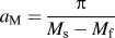 ${a_{\rm{M}}} = {\pi \over {{M_{\rm{s}}} - {M_{\rm{f}}}}}$. A s, A f, M s, and M f are the transformation start and finish temperatures of the austenite and martensite of SMA under stress-free condition, respectively. C A and C M are material constants of SMA related to stress-induced phase transformation.
The equivalent stress of SMA in Eq. (12) can be written into two terms: the first term is the stress of austenite and the second term is the stress of martensite. The equivalent stress of SMA is calculated by the average method using these two terms and the martensite volume fraction. This average method is a frequently used method in the mechanics of composite materials. In this work, due to the gradient of the material and the temperature, the transformation state and stress state in the material are very complex. This average method can help us to get the equivalent stress simply, as well as simplify the calculation and get the analytical solutions.
Many literature studies have investigated the mechanical properties of cylinder under different loads, and most of these investigations treat it as a plane strain problem (εz = 0). However, due to the graded temperature load in this work, there is an obvious deformation along axial direction of the FG-SMA cylinder, and the axial strain is not zero. To consider the axial strain (εz), inspired by the plane section hypothesis commonly used in classical mechanics of materials, a conical surface assumption is proposed in this work. In this assumption, it is assumed that the cross section of the FG-SMA cylinder keeps as a conical surface during the deformation process. Then the strain-displacement relation in this work can be written as
 $${\varepsilon _r}\left( r \right) = {{{\rm{d}}u} / {{\rm{d}}r}},\quad {\varepsilon _\theta }\left( r \right) = {{u\left( r \right)} / r},\quad {\varepsilon _{\rm{z}}}\left( r \right) = a \cdot r + b\quad ,$$
where u is the radial displacement. a and b are undetermined coefficients referring to the conical surface assumption.
The equilibrium functions of the FG-SMA cylinder can be expressed as
 $${{{\rm{d}}{\sigma _{\rm{r}}}\left( r \right)} \over {{\rm{d}}r}} + {{{\sigma _{\rm{r}}}\left( r \right) - {\sigma _\theta }\left( r \right)} \over r} = 0,\quad \int_{{r_1}}^{{r_2}} {{\sigma _{\rm{z}}}\left( r \right){\rm{d}}r = 0} ,\quad \int_{{r_1}}^{{r_2}} {{\sigma _z}\left( r \right)r{\rm{d}}r = 0} \quad .$$
With Eqs. (10)–(16) and the stress boundary conditions: σr(r 1) = −P 1 and σr(r 2) = −P 2, the stress and strain of this FG-SMA cylinder under inner and outer pressure and graded temperature loads can be obtained, and the thermal mechanical behavior of this FG-SMA cylinder can be obtained. Since the volume fraction of martensite ξ is a cosine function of the temperature and equivalent stress of SMA, it is difficult to get the analytical solutions of the stress and strain, and it needs a numerical method to solve these equations.
III. FINITE ELEMENT ANALYSIS
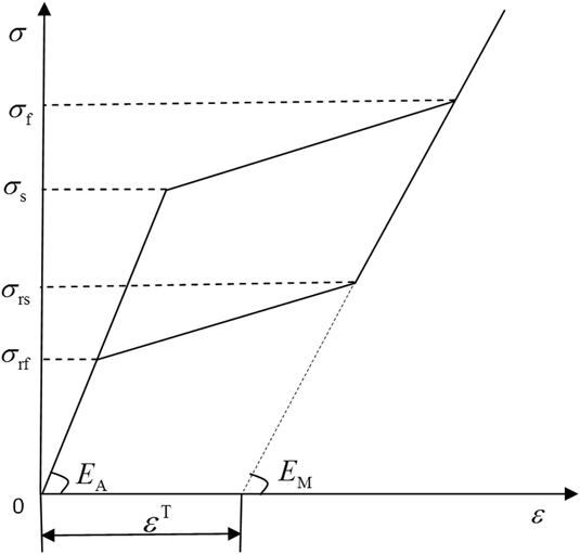
Compared with common FGM, the material properties of FG-SMA vary not only with the gradient direction but also with the variation of stress and temperature during the loading process. To avoid complicated calculation and get relatively accurate results as well, a new layered FEM is provided to simulate the actual FG-SMA cylinder. Specific methods are as follows: the FG-SMA cylinder is divided into m layers with equivalent thickness in the gradient direction (radial direction), and the volume fraction of SMA in each layer is determined by the distribution function f(r); then each layer is divided into two sublayers and the thickness ratio of these two sublayers is determined by the volume fraction of SMA in this layer f(r). The elastic moduli of material A is a constant value, while the constitutive relation of SMA follows the four-line model for simplicity, as shown in Fig. 2, in which the critical stresses σs, σf, σrs, and σrf with different temperatures can be calculated from Eq. (14). It can be concluded that the calculation result is more close to the true value with the increase of the number of layers m. This new layered method can reflect the characteristics of the FG-SMA cylinder fully, avoiding the direct assumption of the macroproperties of the cylinder. The APDL command stream which can be implemented by Ansys 14.0 is written. Once the layer numbers m, the geometric dimensions, and material properties of the component materials of the FG-SMA cylinder are given out, the command stream can establish the FEM, assign the material properties, and mesh and solve automatically.
Stress–strain relation of SMA.

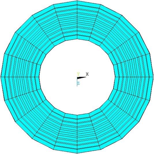
Using the above method, the mechanical behavior of the FG-SMA cylinder subjected to inner and outer pressure and graded temperature loads is investigated. The length of the cylinder is denoted by L, as shown in Fig. 1. With the variation of the loads, the FG-SMA cylinder will undergo a process from elastic deformation to transformation. The FEM of the FG-SMA cylinder is established by two steps: first, a rectangular plane is created and layered to represent different materials as described above, and different material properties were assigned to the corresponding layers; second, the rectangular plane is meshed with the PLANE183 element and then swept to generate the FEM of the FG-SMA cylinder, in which the solid element is SOLID45. The inner and outer pressure and temperature loads are loaded at inner and outer surface of the cylinder, respectively. The obtained FEM is shown in Fig. 3. The above model establishing loading and solving processes are all carried out by the APDL stream automatically.
Cross section of the FEM of the FG-SMA cylinder.

IV. NUMERICAL EXAMPLES AND DISCUSSION
For the purpose of investigating the thermal mechanical behavior of the FG-SMA cylinder clearly, some numerical examples are given here. The length, inner and outer diameters are L = 1 m, r 1 = 0.5 m, and r 2 = 0.8 m, respectively. The elastic moduli of material A, austenite, and martensite are E 0 = 210 GPa, E A = 70 GPa, and E M = 30 GPa, respectively.Reference Bo, Lagoudas and Miller12 The Poisson’s ratio ν = 0.3. The total phase transformation strain εT = 0.069.Reference Zhu and Dui13 The material constants C A = C M = 1.5 MPa/°C.Reference Liang and Rogers11 The initial temperature of the cylinder T 0 = 500 °C. The thermal conductivities of material A and SMA are k 0 = 1.2 W/mK and k 1 = 18 W/mK, respectively.9 The thermal expansion coefficients of material A, austenite, and martensite are α0 = 4 × 10⁻⁶/°C, αA = 11 × 10−6/°C, and αM = 6.6 × 10⁻⁶/°C, respectively.Reference Hamada, Lee, Mizuuchi, Taya and Inoue14 The transformation start and finish temperatures of the austenite and martensite of SMA are A s = 45 °C, A f = 56 °C, M s = 15 °C, and M f = 7 °C, respectively.Reference Zhu and Dui13
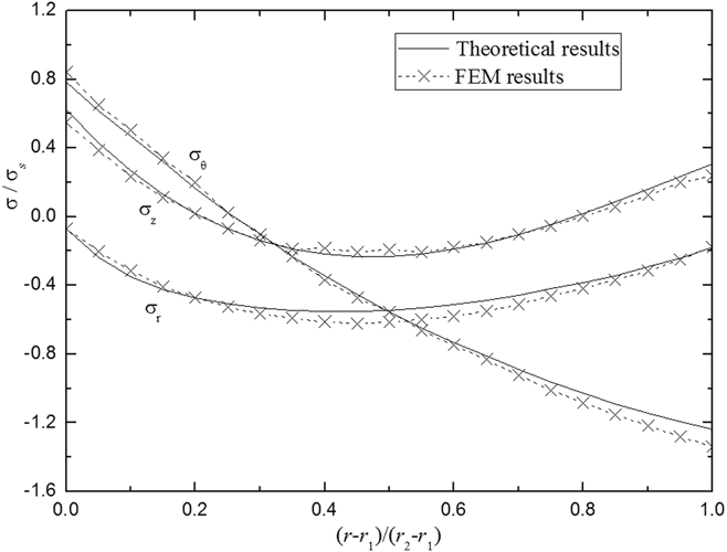
Due to the lack of experimental data of the FG-SMA cylinder subjected to pressure and graded temperature loads, the theoretical results and FEM results of radial stress (σr), circumferential stress (σθ), and axial stress (σz) are shown and compared in Fig. 4, to verify the validity of the theory and FEM method provided in this work. It is easy to find that the theoretical results of σr, σθ, and σz match well with the FEM results, respectively, which indicates that the theory and FEM method provided in this work is valid in describing and predicting the thermal and mechanical properties of the FG-SMA cylinder subjected to pressure and graded temperature loads. Besides, it can also be known from the calculating process that the convergence of the FEM provided in this work is good. It does not have a high requirement on the mesh and load step to achieve convergence, and the nonconvergence case did not occur in the whole calculating process.
Comparison of the theoretical results with FEM results (n = 1; T 1 = 40 °C, T 2 = 80 °C; P 1 = 20 MPa, P 2 = 50 MPa).

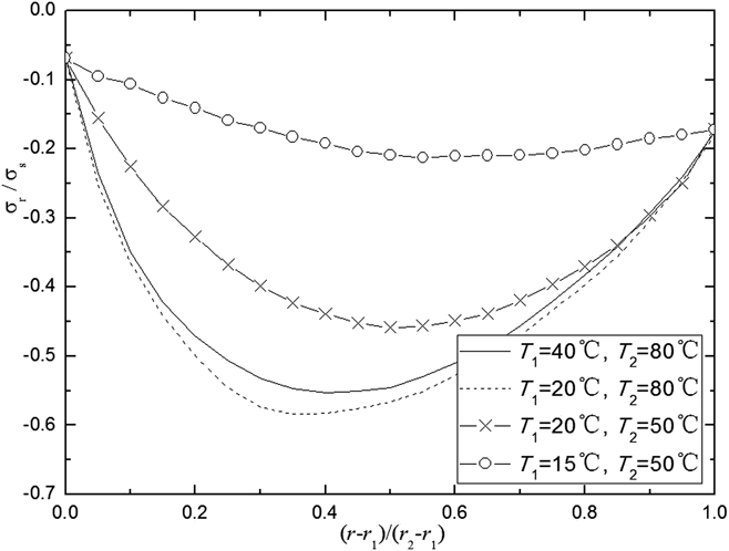
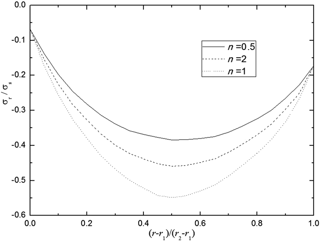
The radial stress distributions along radial direction of the FG-SMA cylinder with different surface temperatures (T 1 and T 2) and different n are shown in Figs. 5 and 6, respectively. In Fig. 5, the two lines with T 2 = 80 °C correspond to the case that only few martensite transformation happens in SMA, while the two lines with T 2 = 50 °C correspond to the case that a lot of martensite transformation happens. It can be seen that the radial stress distributes nonlinearly along the radial direction of the cylinder. The magnitude of radial stress increases and the peak-value position shifts toward the inner surface with the increase of temperature loads (ΔT), when there is little martensite transformation happens. However, with the increase of the martensite transformation, the stress magnitude reduces remarkably, even though the temperature loads (ΔT) increases (from T 1 = 20 °C, T 2 = 50 °C to T 1 = 15 °C, T 2 = 50 °C), which proves the theory that the martensite transformation can reduce the stress of the material, as is known to us. Furthermore, it can be learned from Fig. 6 that the radial stress distribution along the radial direction of the cylinder is affected notably by the distribution function of SMA (different n), while the peak-value position almost unchanged with different n.
Radial stress in the FG-SMA cylinder under different temperatures (n = 1; P 1 = 20 MPa, P 2 = 50 MPa).

Radial stress in the FG-SMA cylinder with different n (T 1 = 20 °C, T 2 = 50 °C; P 1 = 20 MPa, P 2 = 50 MPa).

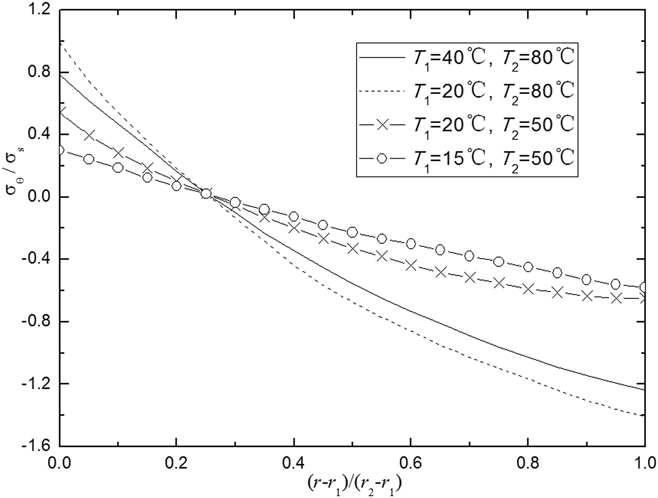
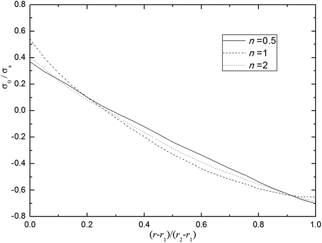
The circumferential stress distributions along the radial direction of the FG-SMA cylinder with different surface temperatures (T 1 and T 2) and different n are shown in Figs. 7 and 8, respectively. Different from radial stress, the circumferential stress distributes approximately linearly in the radial direction, especially in the case that a lot of martensite transformation happens. And it can also be seen that the magnitude of circumferential stress reduces remarkably due to the martensite transformation. Moreover, the distribution of circumferential stress is not notably affected by n, which can be learned from Fig. 8.
Circumferential stress in the FG-SMA cylinder under different temperatures (n = 1; P 1 = 20 MPa, P 2 = 50 MPa).

Circumferential stress in the FG-SMA cylinder with different n (T 1 = 20 °C, T 2 = 50 °C; P 1 = 20 MPa, P 2 = 50 MPa).

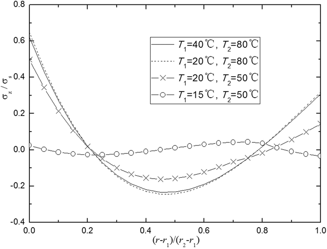
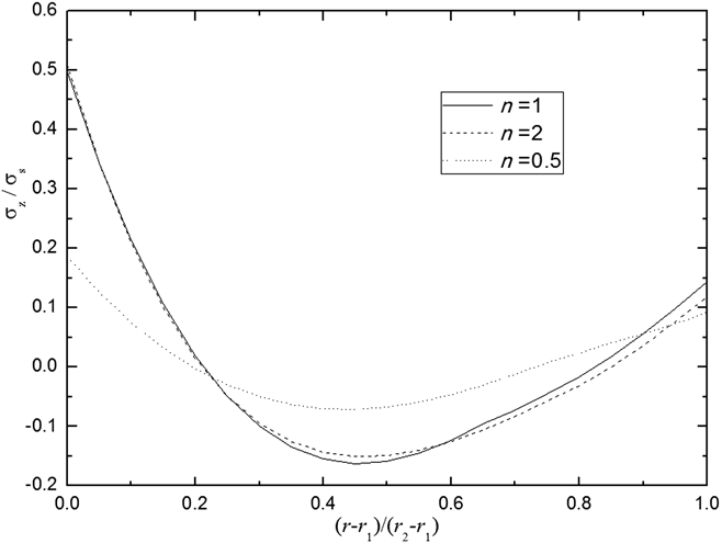
Figures 9 and 10 give out the distributions of axial stress in the FG-SMA cylinder with different surface temperatures (T 1 and T 2) and different n. The characteristics of the distribution of axial stress are similar to that of radial stress, that is, the axial stress distributes nonlinearly and the stress magnitude increases with the increase of temperature loads (ΔT). The magnitude of axial stress reduces remarkably as well, due to the martensite transformation. Furthermore, the distributions of axial stress are very close for n = 1 and 2 but markedly different from n = 0.5. This is also caused by the complex phase transformation field in the FG-SMA cylinder under pressure and graded temperature loads.
Axial stress in the FG-SMA cylinder under different temperatures (n = 1; P 1 = 20 MPa, P 2 = 50 MPa).

Axial stress in the FG-SMA cylinder with different n (T 1 = 20 °C, T 2 = 50 °C; P 1 = 20 MPa, P 2 = 50 MPa).

V. CONCLUSIONS
By bringing in a new concept of conical surface assumption, considering the axial deformation, a macroconstitutive model which can describe the thermal mechanical properties of the FG-SMA cylinder is established in this work, as well as a new layered FEM. With these two models, the thermal mechanical behavior of a FG-SMA cylinder subjected to pressure and graded temperature loads is investigated. It can be seen from numerical results that the temperature in the cylinder distributes nonlinearly under different surface temperatures T 1 and T 2, and the temperature distribution has different forms with different power exponents n. The radial and axial stresses in the cylinder distribute nonlinearly along the radial direction, and the distributions are remarkably affected by the surface temperatures T 1 and T 2 and the power exponent n. However, the circumferential stress distributes almost linearly and it is not notably affected by n. Furthermore, the radial, circumferential, and axial stresses are all decreased a lot due to the martensite transformation.
ACKNOWLEDGMENTS
The authors acknowledge the financial support of National Natural Science Foundation of China (Nos. 11772041, 11272136, 11502284, 11432016, and 11602169) and Tianjin Research Program of Application Foundation and Advanced Technology (16JCQNJC04700). This work is also supported by the Third Level of the “131” Training Funds for Innovative Talents (401009002) of Tianjin, China.