1 Introduction
The flow of droplets on a solid surface is ubiquitous in nature and many industrial applications, ranging from spray coating, crude oil recovery and microfluidics to ink-jet printing (Dupuis & Yeomans Reference Dupuis and Yeomans2005; Blake et al. Reference Blake, Fernandez-Toledano, Doyen and De Coninck2015; Patil et al. Reference Patil, Gada, Sharma and Bhardwaj2016). The droplet dynamics is significantly dependent on the properties of the solid surface, e.g. the wettability (Blake et al. Reference Blake, Fernandez-Toledano, Doyen and De Coninck2015; Shang, Luo & Bai Reference Shang, Luo and Bai2019). Surfactants, interface active agents, can change the wetting properties of a solid surface by altering the contact angle (Lai, Tseng & Huang Reference Lai, Tseng and Huang2010; Xu & Ren Reference Xu and Ren2014; Zhang, Xu & Ren Reference Zhang, Xu and Ren2014). An interesting example in daily life is that detergents (surfactants) are added into a washing machine to clean clothes effectively. Oil droplets that stick to clothes becomes less ‘sticky’ under the effect of surfactants, and the water currents can readily wash away the droplets. Another typical example is surfactant-based enhanced oil recovery in the petroleum industry. Adding surfactants into injected water can greatly improve the efficiency of drainage, since oil droplets attached on the surface of hydrophobic rock are easier to be displaced away (Raffa, Broekhuis & Picchioni Reference Raffa, Broekhuis and Picchioni2016). Surfactants and wettability of reservoir rocks determine the efficiency of drainage and the distribution of residual oil in porous media. In the above examples, water, oil droplets, clothes (rock) and surfactants make up a typical multiphase system involving the moving contact line (MCL) and surfactants. Therefore, an interesting and practically important issue arises concerning how surfactants affect the dynamics of the MCL.
Numerical modelling is taking an increasingly significant position in the investigation of droplet dynamics on a solid surface with surfactants, as it can provide easier access to some quantities such as surfactant concentration, pressure and velocity, which are difficult to measure experimentally (Liu et al. Reference Liu, Ba, Wu, Li, Xi and Zhang2018). However, the efficient and accurate computational modelling of contact line dynamics with surfactants remains a challenging task. The first challenge comes from the modelling of interfacial dynamics with surfactants. The presence of surfactants brings some difficulties to simulations (Booty & Siegel Reference Booty and Siegel2010; Zhang et al. Reference Zhang, Xu and Ren2014; Liu et al. Reference Liu, Ba, Wu, Li, Xi and Zhang2018), including the following: (1) a suitable equation of state is needed to account for the effect of surfactants in reducing the interfacial tension; (2) in addition to the hydrodynamic equations, an advection–diffusion equation should be introduced to describe the evolution of surfactant concentration (Khatri & Tornberg Reference Khatri and Tornberg2014); (3) the non-uniform distribution of surfactants along the interface creates a Marangoni stress, and this effect should be considered in the governing system; and (4) for soluble surfactants, adsorption and desorption of surfactants on the interface further increase the difficulty of modelling (Cuenot, Magnaudet & Spennato Reference Cuenot, Magnaudet and Spennato1997). To address these difficulties, numerous numerical methods have been developed, such as the level set method (Xu, Yang & Lowengrub Reference Xu, Yang and Lowengrub2012; Xu & Ren Reference Xu and Ren2014; Titta et al. Reference Titta, Le Merrer, Detcheverry, Spelt and Biance2018), the volume of fluid method (James & Lowengrub Reference James and Lowengrub2004; Alke & Bothe Reference Alke and Bothe2009), the front tracking method (Zhang, Eckmann & Ayyaswamy Reference Zhang, Eckmann and Ayyaswamy2006; Muradoglu & Tryggvason Reference Muradoglu and Tryggvason2008), the immersed boundary method (Lai et al. Reference Lai, Tseng and Huang2010) and the lattice Boltzmann method (Van der Sman & Van der Graaf Reference Van der Sman and Van der Graaf2006; Zhang et al. Reference Zhang, Kang, Yao, Gao, Sun, Liu and Valocchi2015; Zhao et al. Reference Zhao, Kang, Yao, Viswanathan, Pawar, Zhang and Sun2018; Wei et al. Reference Wei, Hou, Sukop and Liu2019). Although these methods have allowed great progress in the simulation of interfacial flows with surfactants, they still suffer from several drawbacks (Liu et al. Reference Liu, Ba, Wu, Li, Xi and Zhang2018), including the following: (1) the level set and volume of fluid methods require either non-physical re-initialization processes or complex interface reconstruction algorithms to represent the interface and surfactant concentration; (2) the front tracking and immersed boundary methods have difficulty in dealing with large topological changes, for example droplet breakup and coalescence; and (3) most lattice Boltzmann models do not consider the Marangoni stress (Liu et al. Reference Liu, Ba, Wu, Li, Xi and Zhang2018), which is unphysical and could have an important impact on the droplet dynamics. The second challenge is the MCL problem. It is well known that under the usual hydrodynamic assumptions, namely the incompressible Navier–Stokes equations and no-slip boundary condition, non-physical singularities will occur in the vicinity of the MCL, and the velocity field is multi-valued at the contact line (Wang, Qian & Sheng Reference Wang, Qian and Sheng2008; Xu, Di & Yu Reference Xu, Di and Yu2018). To remove the singularities at the MCL, various continuous models have been proposed, and reviews of these models are available (Snoeijer & Andreotti Reference Snoeijer and Andreotti2013; Sui, Ding & Spelt Reference Sui, Ding and Spelt2014). Among these models, the Navier boundary condition (NBC) is a classical and natural boundary condition (Yang et al. Reference Yang, Zhao, Wang and Shen2017; Alpak, Samardžić & Frank Reference Alpak, Samardžić and Frank2018; Zampogna, Magnaudet & Bottaro Reference Zampogna, Magnaudet and Bottaro2019), and it has been used in simulations of contact line dynamics with insoluble surfactants. Lai et al. (Reference Lai, Tseng and Huang2010) used an immersed boundary method to simulate the MCL problem, and studied the effect of insoluble surfactants on contact angles. A level set method for two-phase flows with the MCL and insoluble surfactants was proposed by Xu & Ren (Reference Xu and Ren2014). Zhang et al. (Reference Zhang, Xu and Ren2014) derived a continuous model for the dynamics of two immiscible fluids with the MCL and insoluble surfactants based on thermodynamic principles. Their pioneering studies have greatly promoted the development of simulations for droplet dynamics with the MCL and surfactants. However, the dynamic contact line condition and soluble surfactants were not considered in these studies.
Recently, the phase-field model has shown great potential for the modelling of two-phase flows with the MCL and surfactants. In this model, the interface is treated as a thin diffuse layer between different fluids represented by a phase-field variable (Shen & Yang Reference Shen and Yang2015; Alpak, Riviere & Frank Reference Alpak, Riviere and Frank2016; Frank et al. Reference Frank, Liu, Alpak, Berg and Riviere2018; Kou & Sun Reference Kou and Sun2018a ,Reference Kou and Sun b ). Compared with sharp interface models, the phase-field model has several obvious advantages: (1) it does not need to track the interface explicitly, and the interface is captured implicitly and automatically by the evolution of a phase-field variable (Xu et al. Reference Xu, Di and Yu2018), and thus computations and analysis for the phase-field model are much easier than for other methods and (2) the phase-field model has a firm physical basis for multiphase flow (Liu & Zhang Reference Liu and Zhang2010; Chen, Sun & Wang Reference Chen, Sun and Wang2014), since the governing system can be derived from an energy-based variational formalism, and the developed model normally satisfies thermodynamically consistent energy dissipation law (Shen & Yang Reference Shen and Yang2015; Yang et al. Reference Yang, Zhao, Wang and Shen2017; Zhu et al. Reference Zhu, Chen, Yao and Sun2019a ). These advantages mean that the phase-field model is widely used to simulate interfacial phenomena, e.g. surfactant-driven interfacial flows (Teigen et al. Reference Teigen, Song, Lowengrub and Voigt2011; Yun, Li & Kim Reference Yun, Li and Kim2014). Laradji et al. (Reference Laradji, Guo, Grant and Zuckermann1992) proposed the first phase-field surfactant model. In their pioneering work, two phase-field variables were introduced in the free energy functional, which formed the general framework of phase-field surfactant models, to represent fluid components and surfactant concentration, respectively. Since then, numerous phase-field surfactant models (Copetti & Elliott Reference Copetti and Elliott1992; Komura & Kodama Reference Komura and Kodama1997; Van der Sman & Van der Graaf Reference Van der Sman and Van der Graaf2006) have been proposed and reviews of these models can be found in Li & Kim (Reference Li and Kim2012), Yang & Ju (Reference Yang and Ju2017) and Zhu et al. (Reference Zhu, Kou, Sun, Yao and Li2018). In this study, we adopt a typical representative phase-field surfactant model (free energy functional) developed by Engblom et al. (Reference Engblom, Do-Quang, Amberg and Tornberg2013). In the proposed free energy functional, the classical Cahn–Hilliard potential determines the dynamics of a diffuse interface, and the logarithmic Flory–Huggins potential controls the entropy of mixing surfactants with the bulk phases and restricts the range of concentration variable. The nonlinearly coupled surface energy potential locally attracts surfactants to the interface of fluids, while the enthalpic term globally penalizes free surfactants in the bulk phases and stabilizes the phase-field model. Recently, we coupled this model with the hydrodynamic equations to simulate the interfacial flows with surfactants. Several linear, decoupled and energy-stable schemes were also constructed to solve this complex system effectively (Zhu et al. Reference Zhu, Kou, Sun, Yao and Li2019b ). Our three-dimensional results successfully demonstrate the effect of surfactants on the interfacial dynamics. To date, a series of hydrodynamics coupled phase-field surfactant models have been developed (Pätzold & Dawson Reference Pätzold and Dawson1995; Liu & Zhang Reference Liu and Zhang2010; Teigen et al. Reference Teigen, Song, Lowengrub and Voigt2011; Garcke, Lam & Stinner Reference Garcke, Lam and Stinner2014), but none of them has considered the MCL problem. Hence, it is necessary to extend our current work to the modelling of the MCL problem.
Although the no-slip velocity boundary condition leads to the well-known contact line paradox for sharp interface models, it works well for the phase-field model. The chemical diffusion in a thin interface, arising from the non-equilibrium of chemical potential, can cause the motion of the contact line. Hence, the singularities at the MCL can be successfully removed in the phase-field model when a no-slip boundary condition is imposed. On the other hand, a slip boundary condition also works well for the phase-field model. Using careful molecular dynamics studies of the slip behaviour near the MCL (Qian, Wang & Sheng Reference Qian, Wang and Sheng2004, Reference Qian, Wang and Sheng2006) and principles of thermodynamics, Qian, Wang & Sheng (Reference Qian, Wang and Sheng2003) proposed a generalized Navier boundary condition (GNBC). The GNBC states that the slip velocity at the MCL is proportional to the sum of viscous stress and unbalanced Young stress; the latter arises from the deviation of the fluid–fluid interface from its equilibrium configuration (Wang et al. Reference Wang, Qian and Sheng2008). They further demonstrated that the GNBC can quantitatively reproduce the MCL slip velocity profiles obtained by molecular dynamics simulations (Qian et al. Reference Qian, Wang and Sheng2006). The GNBC can reduce to the typical NBC (Fan et al. Reference Fan, Sun, Yao, Fan and Yang2019) in equilibrium, and the NBC would reduce to the no-slip boundary condition when the slip length of fluid on a solid substrate is zero (Yu & Yang Reference Yu and Yang2017). For the wetting boundary condition, the GNBC uses the typical surface-energy approach (Jacqmin Reference Jacqmin2000; Frank et al. Reference Frank, Liu, Alpak, Berg and Riviere2018) to prescribe a dynamic contact angle between diffuse interface and solid substrate. Note that there are also some other well-known approaches to describe contact angles in the framework of the phase-field model, for example, the geometric contact angle approach derived by Ding & Spelt (Reference Ding and Spelt2007) and the extended geometric approach developed by Alpak et al. (Reference Alpak, Riviere and Frank2016). The GNBC shows great advantages and prospects for simulating the MCL dynamics, and several attempts have been made to develop energy-stable schemes for the GNBC-based phase-field models. In this work, the GNBC is adopted to handle the slip boundary condition and dynamic contact angle at the fluid–solid interface.
As a first attempt, we present a derivation of the phase-field MCL model with soluble surfactants through the first law of thermodynamics, associated thermodynamic relations and the Onsager variational principle. The derived thermodynamically consistent model consists of two Cahn–Hilliard type of equations governing the evolution of interface and surfactant concentration, the incompressible Navier–Stokes equations and the GNBC for the MCL. With chemical potentials derived from the free energy functional, we analytically obtain certain equilibrium properties of surfactant adsorption, including equilibrium profiles for phase-field variables, the Langmuir isotherm and the equilibrium equation of state. A classical droplet spread case is used to numerically validate the MCL model and equilibrium properties of surfactant adsorption. Using the proposed model, we investigate the droplet dynamics with soluble surfactants on a chemically patterned surface.
2 Derivation of MCL hydrodynamics with surfactants
In this section, we present a derivation of the phase-field MCL model with soluble surfactants. The governing equation is derived through three key steps: (1) the first law of thermodynamics and associated thermodynamic relations are used to derive an entropy equation; (2) the momentum equation and the slip boundary condition are obtained through the Galilean invariance; and (3) the Onsager variational principle is used to obtain diffusive fluxes and the stress tensor. The derived model consists of two Cahn–Hilliard type of equations for phase-field variables, the incompressible Navier–Stokes equations and the GNBC for the MCL.
2.1 Free energy functional and entropy equation
In an immiscible two-phase system with soluble surfactants, there are three types of free energy. These are the mixing energy, free energies associated with surfactants and the surface energy at the fluid–solid interface.
Mixing energy. In the phase-field model, a phase-field variable is introduced to distinguish two phases, and the interface is treated as a thin and continuous layer, inside which the two phases are mixed and store the mixing energy. The classical Cahn–Hilliard free energy functional (Gao & Wang Reference Gao and Wang2012; Engblom et al. Reference Engblom, Do-Quang, Amberg and Tornberg2013) is used to represent the mixing energy,
 $$\begin{eqnarray}F_{mix}(\unicode[STIX]{x1D719})=\int \left[-\frac{A}{2}\unicode[STIX]{x1D719}^{2}+\frac{B}{4}\unicode[STIX]{x1D719}^{4}+\frac{A}{4}+\frac{\unicode[STIX]{x1D705}}{2}|\unicode[STIX]{x1D735}\unicode[STIX]{x1D719}|^{2}\right]\text{d}\unicode[STIX]{x1D6FA},\end{eqnarray}$$
where
 $\unicode[STIX]{x1D719}$
is the phase-field variable measuring the local composition of fluids. Parameters
 $A$
,
 $B$
and
 $\unicode[STIX]{x1D705}$
can be determined from the two equilibrium phases
 $\unicode[STIX]{x1D719}_{\pm }=\pm \sqrt{A/B}$
, and the interfacial thickness parameter
 $\unicode[STIX]{x1D700}=\sqrt{\unicode[STIX]{x1D705}/A}$
. The polynomial part
 $-A\unicode[STIX]{x1D719}^{2}/2+B\unicode[STIX]{x1D719}^{4}/4+A/4$
in
 $F_{mix}$
prefers the total separation of two phases and produces the classical sharp-interface picture (Yue et al.
Reference Yue, Feng, Liu and Shen2004). The square gradient term
 $\unicode[STIX]{x1D705}|\unicode[STIX]{x1D735}\unicode[STIX]{x1D719}|^{2}/2$
represents weakly non-local interactions between fluids that prefers the complete mixing of phases. Competition between the two terms leads to a diffuse interface in equilibrium (Shen & Yang Reference Shen and Yang2015), where
 $F_{mix}$
reaches a minimum.
Free energies associated with surfactants. The presence of surfactants would greatly affect the dynamics of fluid mixtures. To account for the effect of surfactants, additional energy terms are introduced to the Cahn–Hilliard free energy functional, including a logarithmic free energy, a nonlinearly coupled surface energy and an energy term measuring the cost of free surfactants.
Free energy
 $F_{1}$
is a typical logarithmic free energy (Yang & Ju Reference Yang and Ju2017) governing the entropy of mixing surfactants with the bulk phases
 $$\begin{eqnarray}\left.\begin{array}{@{}l@{}}F_{1}(\unicode[STIX]{x1D713})=\displaystyle \int \left[k_{b}T_{e}G(\unicode[STIX]{x1D713})\right]\text{d}\unicode[STIX]{x1D6FA},\\ G(\unicode[STIX]{x1D713})=\unicode[STIX]{x1D713}\ln \unicode[STIX]{x1D713}+(1-\unicode[STIX]{x1D713})\ln (1-\unicode[STIX]{x1D713}),\end{array}\right\}\end{eqnarray}$$
where
 $\unicode[STIX]{x1D713}$
is a phase-field variable representing the surfactant concentration,
 $k_{b}$
is the Boltzmann constant and
 $T_{e}$
denotes the temperature. The constant
 $k_{b}T_{e}$
takes the role of a diffusion coefficient for
 $\unicode[STIX]{x1D713}$
at a given temperature. The first term
 $\unicode[STIX]{x1D713}\ln \unicode[STIX]{x1D713}$
in the Flory–Huggins potential
 $G(\unicode[STIX]{x1D713})$
models the ideal mixing of surfactants in the bulk phases and guarantees the value of
 $\unicode[STIX]{x1D713}$
being positive, and the second term
 $(1-\unicode[STIX]{x1D713})\log (1-\unicode[STIX]{x1D713})$
restricts
 $\unicode[STIX]{x1D713}<1$
. Thus, the surfactant concentration
 $\unicode[STIX]{x1D713}$
varies within the range of 0 to 1 in this study.
Surfactants can automatically adsorb onto the interface and form a buffer zone to reduce the system energy. A surface energy
 $F_{2}$
(Engblom et al.
Reference Engblom, Do-Quang, Amberg and Tornberg2013) is adopted to account for the high surfactant concentration near the interface
 $$\begin{eqnarray}F_{2}(\unicode[STIX]{x1D719},\unicode[STIX]{x1D713})=\int \left[-\frac{\unicode[STIX]{x1D701}}{4}\unicode[STIX]{x1D713}(1-\unicode[STIX]{x1D719}^{2})^{2}\right]\text{d}\unicode[STIX]{x1D6FA}.\end{eqnarray}$$
Here we set
 $\unicode[STIX]{x1D701}=A$
to reduce unnecessary free parameters (Engblom et al.
Reference Engblom, Do-Quang, Amberg and Tornberg2013). Theoretically, the surface energy
 $F_{2}$
is inactive in the bulk phases and reaches a minimum on the interface. The energy term
 $F_{3}$
is used to penalize free surfactants in the bulk phases:
 $$\begin{eqnarray}F_{3}(\unicode[STIX]{x1D719},\unicode[STIX]{x1D713})=\int \left[\frac{W}{2}\unicode[STIX]{x1D713}\unicode[STIX]{x1D719}^{2}\right]\text{d}\unicode[STIX]{x1D6FA},\end{eqnarray}$$
where
 $W$
is a positive parameter. Surface energy
 $F_{3}$
also plays a significant role in stabilizing the phase-field model (Liu & Zhang Reference Liu and Zhang2010). It is obvious that
 $F_{3}$
is inactive on the interface where
 $\unicode[STIX]{x1D719}$
 ${\approx}$
0 and reaches a maximum in the bulk phases. To some extent,
 $F_{2}$
and
 $F_{3}$
are complementary;
 $F_{2}$
locally attracts surfactants to the interface while
 $F_{3}$
globally counteracts the occurrence of free surfactants (Engblom et al.
Reference Engblom, Do-Quang, Amberg and Tornberg2013).
Surface energy at the fluid–solid interface. When the diffuse interface touches a solid surface, the MCL problem arises. The interfacial free energy per unit area
 $M(\unicode[STIX]{x1D719})$
at the fluid–solid interface is determined by the interfacial tension
 $\unicode[STIX]{x1D70E}$
between fluids, the contact angle
 $\unicode[STIX]{x1D703}_{s}$
between the diffuse interface and solid surface, and the local composition of fluids on the solid surface. The typical free energy at the fluid–solid surface (Gao & Wang Reference Gao and Wang2014) reads
 $$\begin{eqnarray}F_{wf}(\unicode[STIX]{x1D719})=\int M(\unicode[STIX]{x1D719})\,\text{d}S=\int \left[-\frac{\unicode[STIX]{x1D70E}}{2}\cos \unicode[STIX]{x1D703}_{s}\sin \left(\frac{\unicode[STIX]{x03C0}}{2}\unicode[STIX]{x1D719}\right)\right]\text{d}S.\end{eqnarray}$$
The total free energy
 $F$
of a two-phase system with soluble surfactants can be written as the sum of the mixing energy, free energies associated with surfactants and the free energy at the fluid–solid interface:
 $$\begin{eqnarray}F(\unicode[STIX]{x1D719},\unicode[STIX]{x1D713})=F_{mix}(\unicode[STIX]{x1D719})+F_{1}(\unicode[STIX]{x1D713})+F_{2}(\unicode[STIX]{x1D719},\unicode[STIX]{x1D713})+F_{3}(\unicode[STIX]{x1D719},\unicode[STIX]{x1D713})+F_{wf}(\unicode[STIX]{x1D719}).\end{eqnarray}$$
The three quantities
 $w_{\unicode[STIX]{x1D719}}$
,
 $w_{\unicode[STIX]{x1D713}}$
and
 $L$
can be variationally derived from the total free energy
 $F$
as
 $$\begin{eqnarray}\unicode[STIX]{x1D6FF}F(\unicode[STIX]{x1D719},\unicode[STIX]{x1D713})=\int [w_{\unicode[STIX]{x1D719}}\unicode[STIX]{x1D6FF}\unicode[STIX]{x1D719}]\,\text{d}\unicode[STIX]{x1D6FA}+\int [w_{\unicode[STIX]{x1D713}}\,\unicode[STIX]{x1D6FF}\unicode[STIX]{x1D713}]\,\text{d}\unicode[STIX]{x1D6FA}+\int [L\,\unicode[STIX]{x1D6FF}\unicode[STIX]{x1D719}]\,\text{d}S,\end{eqnarray}$$
where
 $w_{\unicode[STIX]{x1D719}}$
is the chemical potential determining the composition diffusion as follows:
 $$\begin{eqnarray}w_{\unicode[STIX]{x1D719}}=-A\unicode[STIX]{x1D719}+B\unicode[STIX]{x1D719}^{3}-\unicode[STIX]{x1D705}\unicode[STIX]{x0394}\unicode[STIX]{x1D719}+W\unicode[STIX]{x1D713}\unicode[STIX]{x1D719}-\unicode[STIX]{x1D701}\unicode[STIX]{x1D713}\unicode[STIX]{x1D719}(\unicode[STIX]{x1D719}^{2}-1).\end{eqnarray}$$
Equation (2.8) indicates that the surfactant concentration may greatly affect the composition diffusion, and change the equilibrium profile of the phase-field variable
 $\unicode[STIX]{x1D719}$
. A detailed discussion of this issue will be presented in § 3. The variable
 $w_{\unicode[STIX]{x1D713}}$
is the chemical potential governing the diffusion of surfactants,
 $$\begin{eqnarray}w_{\unicode[STIX]{x1D713}}=k_{b}T_{e}\ln \left(\frac{\unicode[STIX]{x1D713}}{1-\unicode[STIX]{x1D713}}\right)+\frac{W}{2}\unicode[STIX]{x1D719}^{2}-\frac{\unicode[STIX]{x1D701}}{4}(\unicode[STIX]{x1D719}^{2}-1)^{2},\end{eqnarray}$$
and
 $L$
is the chemical potential at the solid surface,
 $$\begin{eqnarray}L=\unicode[STIX]{x1D705}\unicode[STIX]{x2202}_{n}\unicode[STIX]{x1D719}+M^{\prime }(\unicode[STIX]{x1D719}).\end{eqnarray}$$
By minimizing the total free energy
 $F$
with respect to phase-field variables
 $\unicode[STIX]{x1D719}$
and
 $\unicode[STIX]{x1D713}$
, we can obtain equilibrium conditions, where chemical potentials are constants throughout the whole system. Deviations from equilibrium conditions, measured by the chemical potential gradients
 $\unicode[STIX]{x1D735}w_{\unicode[STIX]{x1D719}}$
and
 $\unicode[STIX]{x1D735}w_{\unicode[STIX]{x1D713}}$
in the bulk phases and
 $L$
at the fluid–solid interface (Qian et al.
Reference Qian, Wang and Sheng2006), will lead to composition diffusion, surfactant diffusion in the bulk phases and relaxation at the fluid–solid interface. The conservation of
 $\unicode[STIX]{x1D719}$
and
 $\unicode[STIX]{x1D713}$
requires that diffusive fluxes and material derivatives of phase-field variables satisfy the continuity equation, namely
 $$\begin{eqnarray}\dot{\unicode[STIX]{x1D719}}=\unicode[STIX]{x1D719}_{t}+\boldsymbol{u}\boldsymbol{\cdot }\unicode[STIX]{x1D735}\unicode[STIX]{x1D719}=-\unicode[STIX]{x1D735}\boldsymbol{\cdot }\boldsymbol{J}_{\unicode[STIX]{x1D719}}\end{eqnarray}$$
and
 $$\begin{eqnarray}\dot{\unicode[STIX]{x1D713}}=\unicode[STIX]{x1D713}_{t}+\boldsymbol{u}\boldsymbol{\cdot }\unicode[STIX]{x1D735}\unicode[STIX]{x1D713}=-\unicode[STIX]{x1D735}\boldsymbol{\cdot }\boldsymbol{J}_{\unicode[STIX]{x1D713}},\end{eqnarray}$$
where
 $\boldsymbol{J}_{\unicode[STIX]{x1D719}}$
and
 $\boldsymbol{J}_{\unicode[STIX]{x1D713}}$
are diffusive fluxes resulting from the composition diffusion and surfactant diffusion, respectively. The variable
 $\boldsymbol{u}$
is the flow velocity field. The relaxation arising from
 $L$
can be described by the material derivative
 $\unicode[STIX]{x1D719}$
at the solid surface, i.e.
 $\dot{\unicode[STIX]{x1D719}}=\unicode[STIX]{x1D719}_{t}+\boldsymbol{u}_{\unicode[STIX]{x1D70F}}\unicode[STIX]{x2202}_{\unicode[STIX]{x1D70F}}\unicode[STIX]{x1D719}$
, where
 $\boldsymbol{u}_{\unicode[STIX]{x1D70F}}$
is the tangential velocity of fluid on the solid surface. The mass conservation of system requires that
 $$\begin{eqnarray}\dot{\unicode[STIX]{x1D70C}}=\unicode[STIX]{x1D70C}_{t}+\boldsymbol{u}\boldsymbol{\cdot }\unicode[STIX]{x1D735}\unicode[STIX]{x1D70C}=-\unicode[STIX]{x1D735}\boldsymbol{\cdot }\boldsymbol{J},\end{eqnarray}$$
where
 $\unicode[STIX]{x1D70C}$
is the fluid density and
 $\boldsymbol{J}$
is the diffusive mass flux, which is determined by the diffusive flux
 $\boldsymbol{J}_{\unicode[STIX]{x1D719}}$
and density difference between fluids.
Now we will combine the first law of thermodynamics and classical thermodynamic relations to derive the entropy balance equation. Then, we can obtain the momentum equation and the slip boundary condition using the Galilean invariance.
Similar to the variation of the total free energy
 $F$
, the rate of change of
 $F$
can be written as
 $$\begin{eqnarray}{\dot{F}}=\int [w_{\unicode[STIX]{x1D719}}\unicode[STIX]{x1D719}_{t}]\,\text{d}\unicode[STIX]{x1D6FA}+\int [w_{\unicode[STIX]{x1D713}}\unicode[STIX]{x1D713}_{t}]\,\text{d}\unicode[STIX]{x1D6FA}+\int [L\unicode[STIX]{x1D719}_{t}]\,\text{d}S.\end{eqnarray}$$
Substituting (2.11), (2.12) and
 $\unicode[STIX]{x1D719}_{t}=\dot{\unicode[STIX]{x1D719}}-\boldsymbol{u}_{\unicode[STIX]{x1D70F}}\unicode[STIX]{x2202}_{\unicode[STIX]{x1D70F}}\unicode[STIX]{x1D719}$
into (2.14), we obtain
 $$\begin{eqnarray}\displaystyle {\dot{F}} & = & \displaystyle \int [-w_{\unicode[STIX]{x1D719}}\unicode[STIX]{x1D735}\boldsymbol{\cdot }\boldsymbol{J}_{\unicode[STIX]{x1D719}}-w_{\unicode[STIX]{x1D719}}\boldsymbol{u}\boldsymbol{\cdot }\unicode[STIX]{x1D735}\unicode[STIX]{x1D719}]\,\text{d}\unicode[STIX]{x1D6FA}+\int [-w_{\unicode[STIX]{x1D713}}\unicode[STIX]{x1D735}\boldsymbol{\cdot }\boldsymbol{J}_{\unicode[STIX]{x1D713}}-w_{\unicode[STIX]{x1D713}}\boldsymbol{u}\boldsymbol{\cdot }\unicode[STIX]{x1D735}\unicode[STIX]{x1D713}]\,\text{d}\unicode[STIX]{x1D6FA}\nonumber\\ \displaystyle & & \displaystyle +\,\int [L(\dot{\unicode[STIX]{x1D719}}-\boldsymbol{u}_{\unicode[STIX]{x1D70F}}\unicode[STIX]{x2202}_{\unicode[STIX]{x1D70F}}\unicode[STIX]{x1D719})]\,\text{d}S.\end{eqnarray}$$
Considering the fact that normal diffusion fluxes disappear at the solid surface because of the impermeability condition, specifically
 $\boldsymbol{J}_{\unicode[STIX]{x1D719}}\boldsymbol{\cdot }\boldsymbol{n}|_{\mathit{S}}=0$
and
 $\boldsymbol{J}_{\unicode[STIX]{x1D713}}\boldsymbol{\cdot }\boldsymbol{n}|_{\mathit{S}}=0$
, we obtain identities
 $$\begin{eqnarray}-\int [w_{\unicode[STIX]{x1D719}}\unicode[STIX]{x1D735}\boldsymbol{\cdot }\boldsymbol{J}_{\unicode[STIX]{x1D719}}]\,\text{d}\unicode[STIX]{x1D6FA}=-\int [w_{\unicode[STIX]{x1D719}}\boldsymbol{J}_{\unicode[STIX]{x1D719}}\boldsymbol{\cdot }\boldsymbol{n}]\text{d}S+\int [\unicode[STIX]{x1D735}w_{\unicode[STIX]{x1D719}}\boldsymbol{\cdot }\boldsymbol{J}_{\unicode[STIX]{x1D719}}]\,\text{d}\unicode[STIX]{x1D6FA}=\int [\unicode[STIX]{x1D735}w_{\unicode[STIX]{x1D719}}\boldsymbol{\cdot }\boldsymbol{J}_{\unicode[STIX]{x1D719}}]\,\text{d}\unicode[STIX]{x1D6FA}\end{eqnarray}$$
and
 $-\!\int [w_{\unicode[STIX]{x1D713}}\unicode[STIX]{x1D735}\boldsymbol{\cdot }\boldsymbol{J}_{\unicode[STIX]{x1D713}}]\,\text{d}\unicode[STIX]{x1D6FA}=\int [\unicode[STIX]{x1D735}w_{\unicode[STIX]{x1D713}}\boldsymbol{\cdot }\boldsymbol{J}_{\unicode[STIX]{x1D713}}]\,\text{d}\unicode[STIX]{x1D6FA}$
. Similarly, we can obtain
 $-\!\int [w_{\unicode[STIX]{x1D719}}\boldsymbol{u}\boldsymbol{\cdot }\unicode[STIX]{x1D735}\unicode[STIX]{x1D719}]\,\text{d}\unicode[STIX]{x1D6FA}=\int [\unicode[STIX]{x1D719}\boldsymbol{u}\boldsymbol{\cdot }\unicode[STIX]{x1D735}w_{\unicode[STIX]{x1D719}}]\,\text{d}\unicode[STIX]{x1D6FA}$
and
 $-\!\int [w_{\unicode[STIX]{x1D713}}\boldsymbol{u}\boldsymbol{\cdot }\unicode[STIX]{x1D735}\unicode[STIX]{x1D713}]\,\text{d}\unicode[STIX]{x1D6FA}=\int [\unicode[STIX]{x1D713}\boldsymbol{u}\boldsymbol{\cdot }\unicode[STIX]{x1D735}w_{\unicode[STIX]{x1D713}}]\,\text{d}\unicode[STIX]{x1D6FA}$
using the boundary condition
 $\boldsymbol{u}\boldsymbol{\cdot }\boldsymbol{n}|_{\mathit{S}}=0$
, where
 $\boldsymbol{n}$
is the unit vector orthogonal to boundaries. Then (2.15) can be rewritten as
 $$\begin{eqnarray}{\dot{F}}=\int [\unicode[STIX]{x1D735}w_{\unicode[STIX]{x1D719}}\boldsymbol{\cdot }\boldsymbol{J}_{\unicode[STIX]{x1D719}}+\unicode[STIX]{x1D735}w_{\unicode[STIX]{x1D713}}\boldsymbol{\cdot }\boldsymbol{J}_{\unicode[STIX]{x1D713}}]\,\text{d}\unicode[STIX]{x1D6FA}+\int [\unicode[STIX]{x1D719}\boldsymbol{u}\boldsymbol{\cdot }\unicode[STIX]{x1D735}w_{\unicode[STIX]{x1D719}}+\unicode[STIX]{x1D713}\boldsymbol{u}\boldsymbol{\cdot }\unicode[STIX]{x1D735}w_{\unicode[STIX]{x1D713}}]\,\text{d}\unicode[STIX]{x1D6FA}+\int [L\dot{\unicode[STIX]{x1D719}}-L\boldsymbol{u}_{\unicode[STIX]{x1D70F}}\unicode[STIX]{x2202}_{\unicode[STIX]{x1D70F}}\unicode[STIX]{x1D719}]\,\text{d}S.\end{eqnarray}$$
The first law of thermodynamics states that
 $$\begin{eqnarray}(\dot{U}+{\dot{E}}_{k})={\dot{W}}+\dot{Q},\end{eqnarray}$$
where
 $U$
is the internal energy,
 $W$
is the work done by the face force
 $F_{t}$
and
 $Q$
denotes the heat from the surroundings that keeps the system temperature constant. The variable
 $E_{k}$
is the kinetic energy, and it is defined as
 $E_{k}=\frac{1}{2}\int [\unicode[STIX]{x1D70C}|\boldsymbol{u}|^{2}]\,\text{d}\unicode[STIX]{x1D6FA}$
. The total entropy
 $S$
is contributed by two components, namely the entropy of the system
 $S_{\mathit{sys}}$
and the entropy of the surroundings
 $S_{\mathit{surr}}$
, the latter of which is related to
 $Q$
as
 ${\dot{S}}_{\mathit{surr}}=-\dot{Q}/T$
. Using the thermodynamic relation
 $\dot{U}={\dot{F}}+T{\dot{S}}_{\mathit{sys}}$
, we have
 $$\begin{eqnarray}{\dot{S}}={\dot{S}}_{\mathit{sys}}+{\dot{S}}_{\mathit{surr}}={\dot{S}}_{\mathit{sys}}-\frac{\dot{Q}}{T}=-\frac{1}{T}({\dot{F}}+{\dot{E}}_{k})+\frac{1}{T}{\dot{W}}.\end{eqnarray}$$
Applying the Reynolds transport theorem and the Gauss divergence theorem, we can derive that
 $$\begin{eqnarray}\displaystyle {\dot{E}}_{k} & = & \displaystyle \frac{1}{2}\int \left[\frac{\unicode[STIX]{x2202}(\unicode[STIX]{x1D70C}\boldsymbol{u}\boldsymbol{\cdot }\boldsymbol{u})}{\unicode[STIX]{x2202}t}\right]\text{d}\unicode[STIX]{x1D6FA}+\frac{1}{2}\int [\unicode[STIX]{x1D735}\boldsymbol{\cdot }([\unicode[STIX]{x1D70C}\boldsymbol{u}\boldsymbol{\cdot }\boldsymbol{u}]\boldsymbol{u})]\,\text{d}\unicode[STIX]{x1D6FA}\nonumber\\ \displaystyle & = & \displaystyle \int \left[\unicode[STIX]{x1D70C}\boldsymbol{u}\boldsymbol{\cdot }\boldsymbol{u}_{t}+\frac{1}{2}\boldsymbol{u}\boldsymbol{\cdot }\boldsymbol{u}\unicode[STIX]{x1D70C}_{t}\right]\text{d}\unicode[STIX]{x1D6FA}\nonumber\\ \displaystyle & & \displaystyle +\,\frac{1}{2}\int \left[(\unicode[STIX]{x1D70C}\boldsymbol{u}\boldsymbol{\cdot }\boldsymbol{u})\unicode[STIX]{x1D735}\boldsymbol{\cdot }\boldsymbol{u}+(\boldsymbol{u}\boldsymbol{\cdot }\boldsymbol{u})\boldsymbol{u}\boldsymbol{\cdot }\unicode[STIX]{x1D735}\unicode[STIX]{x1D70C}+\unicode[STIX]{x1D70C}\boldsymbol{u}\boldsymbol{\cdot }\unicode[STIX]{x1D735}(\boldsymbol{u}\boldsymbol{\cdot }\boldsymbol{u})\right]\text{d}\unicode[STIX]{x1D6FA}\nonumber\\ \displaystyle & = & \displaystyle \int [\boldsymbol{u}\boldsymbol{\cdot }(\unicode[STIX]{x1D70C}\boldsymbol{u}_{t}+\unicode[STIX]{x1D70C}\boldsymbol{u}\boldsymbol{\cdot }\unicode[STIX]{x1D735}\boldsymbol{u})]\,\text{d}\unicode[STIX]{x1D6FA}+\frac{1}{2}\int [(\boldsymbol{u}\boldsymbol{\cdot }\boldsymbol{u})(\unicode[STIX]{x1D70C}_{t}+\boldsymbol{u}\boldsymbol{\cdot }\unicode[STIX]{x1D735}\unicode[STIX]{x1D70C})]\,\text{d}\unicode[STIX]{x1D6FA}.\end{eqnarray}$$
Substituting (2.13) into (2.20), and using integration by parts, we have
 $$\begin{eqnarray}{\dot{E}}_{k}=\int [\boldsymbol{u}\boldsymbol{\cdot }(\unicode[STIX]{x1D70C}\boldsymbol{u}_{t}+\unicode[STIX]{x1D70C}\boldsymbol{u}\boldsymbol{\cdot }\unicode[STIX]{x1D735}\boldsymbol{u}+\boldsymbol{J}\boldsymbol{\cdot }\unicode[STIX]{x1D735}\boldsymbol{u})]\,\text{d}\unicode[STIX]{x1D6FA}.\end{eqnarray}$$
The work done by the stress
 $\unicode[STIX]{x1D748}$
and the fraction force
 $\boldsymbol{f}_{s}$
at the fluid–solid interface is expressed as
 $$\begin{eqnarray}{\dot{W}}=-\int [\unicode[STIX]{x1D748}^{\text{T}}\mathbf{: }\unicode[STIX]{x1D735}\boldsymbol{u}+\boldsymbol{u}\boldsymbol{\cdot }(\unicode[STIX]{x1D735}\boldsymbol{\cdot }\unicode[STIX]{x1D748})]\,\text{d}\unicode[STIX]{x1D6FA}+\int [(\unicode[STIX]{x1D748}\boldsymbol{\cdot }\boldsymbol{n})\boldsymbol{\cdot }\boldsymbol{u}_{s}]\,\text{d}S+\int [\,\boldsymbol{f}_{\unicode[STIX]{x1D70F}}\boldsymbol{\cdot }\boldsymbol{u}_{s}]\,\text{d}S,\end{eqnarray}$$
where
 $\boldsymbol{u}_{s}$
is the slip velocity of fluids relative to the solid wall. Note that
 $\boldsymbol{u}_{s}$
is equal to
 $\boldsymbol{u}_{\unicode[STIX]{x1D70F}}$
when the solid wall is static.
Substituting (2.17), (2.21) and (2.22) into (2.19), we can obtain the entropy balance equation
 $$\begin{eqnarray}\displaystyle T{\dot{S}} & = & \displaystyle -\int [\boldsymbol{u}\boldsymbol{\cdot }(\unicode[STIX]{x1D70C}\boldsymbol{u}_{t}+\unicode[STIX]{x1D70C}\boldsymbol{u}\boldsymbol{\cdot }\unicode[STIX]{x1D735}\boldsymbol{u}+\boldsymbol{J}\boldsymbol{\cdot }\unicode[STIX]{x1D735}\boldsymbol{u}+\unicode[STIX]{x1D735}\boldsymbol{\cdot }\unicode[STIX]{x1D748}+\unicode[STIX]{x1D719}\unicode[STIX]{x1D735}w_{\unicode[STIX]{x1D719}}+\unicode[STIX]{x1D713}\unicode[STIX]{x1D735}w_{\unicode[STIX]{x1D713}})]\,\text{d}\unicode[STIX]{x1D6FA}\nonumber\\ \displaystyle & & \displaystyle -\,\int [\unicode[STIX]{x1D748}^{\text{T}}\mathbf{: }\unicode[STIX]{x1D735}\boldsymbol{u}-\boldsymbol{J}_{\unicode[STIX]{x1D719}}\boldsymbol{\cdot }\unicode[STIX]{x1D735}w_{\unicode[STIX]{x1D719}}-\boldsymbol{J}_{\unicode[STIX]{x1D713}}\boldsymbol{\cdot }\unicode[STIX]{x1D735}w_{\unicode[STIX]{x1D713}}]\,\text{d}\unicode[STIX]{x1D6FA}-\int [L\dot{\unicode[STIX]{x1D719}}]\,\text{d}S\nonumber\\ \displaystyle & & \displaystyle +\,\int \boldsymbol{u}_{\unicode[STIX]{x1D70F}}\boldsymbol{\cdot }[\unicode[STIX]{x1D748}\boldsymbol{\cdot }\boldsymbol{n}+\boldsymbol{f}_{s}+L\unicode[STIX]{x2202}_{\unicode[STIX]{x1D70F}}\unicode[STIX]{x1D719}]\,\text{d}S.\end{eqnarray}$$
The Galilean invariance yields from (2.23)
 $$\begin{eqnarray}\unicode[STIX]{x1D70C}\boldsymbol{u}_{t}+\unicode[STIX]{x1D70C}\boldsymbol{u}\boldsymbol{\cdot }\unicode[STIX]{x1D735}\boldsymbol{u}+\boldsymbol{J}\boldsymbol{\cdot }\unicode[STIX]{x1D735}\boldsymbol{u}+\unicode[STIX]{x1D735}\boldsymbol{\cdot }\unicode[STIX]{x1D748}+\unicode[STIX]{x1D719}\unicode[STIX]{x1D735}w_{\unicode[STIX]{x1D719}}+\unicode[STIX]{x1D713}\unicode[STIX]{x1D735}w_{\unicode[STIX]{x1D713}}=0\end{eqnarray}$$
in the bulk phases and
 $$\begin{eqnarray}(\unicode[STIX]{x1D748}\boldsymbol{\cdot }\boldsymbol{n}+\boldsymbol{f}_{s}+L\unicode[STIX]{x2202}_{\unicode[STIX]{x1D70F}}\unicode[STIX]{x1D719})\boldsymbol{\cdot }\unicode[STIX]{x1D749}=0\end{eqnarray}$$
at the fluid–solid interface. Equation (2.24) is the Navier–Stokes equation for two-phase flows with soluble surfactants and equation (2.25) is the slip boundary condition. The total stress tensor can be split into
 $\unicode[STIX]{x1D748}=p\unicode[STIX]{x1D644}+\unicode[STIX]{x1D748}_{\mathit{irrev}}$
, where p is the reversible part, i.e. the pressure, and
 $\unicode[STIX]{x1D748}_{\mathit{irrev}}$
is the irreversible part. With the incompressibility constraint
 $\unicode[STIX]{x1D735}\boldsymbol{\cdot }\boldsymbol{u}=0$
, we can derive that
 $$\begin{eqnarray}\unicode[STIX]{x1D748}^{\text{T}}\mathbf{: }\unicode[STIX]{x1D735}\boldsymbol{u}=p\unicode[STIX]{x1D735}\boldsymbol{\cdot }\boldsymbol{u}+\unicode[STIX]{x1D748}_{\mathit{irrev}}^{\text{T}}\mathbf{: }\unicode[STIX]{x1D735}\boldsymbol{u}=\unicode[STIX]{x1D748}_{\mathit{irrev}}^{\text{T}}\mathbf{: }\unicode[STIX]{x1D735}\boldsymbol{u},\end{eqnarray}$$
and (2.25) can reduce to
 $$\begin{eqnarray}(\unicode[STIX]{x1D748}_{\mathit{irrev}}\boldsymbol{\cdot }\boldsymbol{n}+\boldsymbol{f}_{s}+L\unicode[STIX]{x2202}_{\unicode[STIX]{x1D70F}}\unicode[STIX]{x1D719})\boldsymbol{\cdot }\unicode[STIX]{x1D749}=0.\end{eqnarray}$$
Thus, the entropy balance equation (2.23) is simplified as
 $$\begin{eqnarray}-T{\dot{S}}=\int [\unicode[STIX]{x1D748}_{\mathit{irrev}}^{\text{T}}\mathbf{: }\unicode[STIX]{x1D735}\boldsymbol{u}+\boldsymbol{J}_{\unicode[STIX]{x1D719}}\boldsymbol{\cdot }\unicode[STIX]{x1D735}w_{\unicode[STIX]{x1D719}}+\boldsymbol{J}_{\unicode[STIX]{x1D713}}\boldsymbol{\cdot }\unicode[STIX]{x1D735}w_{\unicode[STIX]{x1D713}}]\,\text{d}\unicode[STIX]{x1D6FA}+\int [L\dot{\unicode[STIX]{x1D719}}]\,\text{d}S.\end{eqnarray}$$
Next, we will use the entropy balance equation (2.28) and the dissipation function to obtain diffusive fluxes and the irreversible stress tensor.
2.2 Onsager’s variational principle
An irreversible process (e.g. diffusion) taking place in a thermodynamic system leads to dissipation, and the principle of minimum energy dissipation produces the most probable course of an irreversible process when deviations from equilibrium conditions are small. For a multiphase system with MCL and soluble surfactants, there are several physically distinct sources of dissipations, and now we will discuss them in detail. The work done by a fluid on adjacent layers due to the action of shear force is transformed into heat, and this irreversible process is called viscous dissipation. The rate of viscous dissipation in the bulk phases
 $R_{v}$
can be written as
 $$\begin{eqnarray}R_{v}(\boldsymbol{u})=\int \left[\frac{\unicode[STIX]{x1D748}_{\mathit{irrev}}^{2}}{\unicode[STIX]{x1D702}}\right]\text{d}\unicode[STIX]{x1D6FA},\end{eqnarray}$$
where
 $\unicode[STIX]{x1D702}$
is the fluid viscosity. Obviously,
 $R_{v}$
is positive definite and quadratic in the rate
 $\unicode[STIX]{x1D748}_{\mathit{irrev}}$
.
As we mentioned before, chemical potential gradients in the bulk phases and
 $L$
at the fluid–solid interface measure deviations from equilibrium conditions. The diffusive flux
 $\boldsymbol{J}_{\unicode[STIX]{x1D719}}$
arising from
 $\unicode[STIX]{x1D735}w_{\unicode[STIX]{x1D719}}$
, the diffusive flux
 $\boldsymbol{J}_{\unicode[STIX]{x1D713}}$
resulting from
 $\unicode[STIX]{x1D735}w_{\unicode[STIX]{x1D713}}$
and the composition relaxation
 $\dot{\unicode[STIX]{x1D719}}$
at the solid surface coming from
 $L$
are sources of additional energy dissipation. According to the general rule governing entropy production in a thermodynamic process, the addition rate of dissipation
 $R_{t}$
should be positive definite and quadratic in the rates
 $\{\boldsymbol{J}_{\unicode[STIX]{x1D719}},\dot{\unicode[STIX]{x1D719}}\text{ and }\boldsymbol{J}_{\unicode[STIX]{x1D713}}\}$
, e.g.
 $R_{t}=R_{d}+R_{ds}+R_{r}$
, where
 $$\begin{eqnarray}R_{d}(\unicode[STIX]{x1D719})=\int \left[\frac{\boldsymbol{J}_{\unicode[STIX]{x1D719}}^{2}}{M_{\unicode[STIX]{x1D719}}}\right]\text{d}\unicode[STIX]{x1D6FA},\quad R_{ds}(\unicode[STIX]{x1D713})=\int \left[\frac{\boldsymbol{J}_{\unicode[STIX]{x1D713}}^{2}}{M_{\unicode[STIX]{x1D713}}}\right]\text{d}\unicode[STIX]{x1D6FA},\quad R_{r}(\unicode[STIX]{x1D719})=\int \left[\frac{\dot{\unicode[STIX]{x1D719}}^{2}}{\unicode[STIX]{x1D6E4}}\right]\text{d}S.\end{eqnarray}$$
Here
 $R_{d}$
comes from the composition diffusion,
 $R_{ds}$
arises from the diffusion associated with surfactants and
 $R_{r}$
is attributed to the composition relaxation at the solid surface. Parameters
 $M_{\unicode[STIX]{x1D719}}$
,
 $M_{\unicode[STIX]{x1D713}}$
and
 $\unicode[STIX]{x1D6E4}$
are phenomenological parameters. Now we can obtain the free energy dissipation for a two-phase system with MCL and soluble surfactants
 $R=R_{v}+R_{d}+R_{ds}+R_{r}$
.
The Onsager variation principle (Onsager Reference Onsager1931a
,Reference Onsager
b
; Qian et al.
Reference Qian, Wang and Sheng2006) states that for an open system, the state evolution equation can be obtained by minimizing
 $\unicode[STIX]{x1D6F7}-T{\dot{S}}$
with respect to the rates
 $\{\boldsymbol{J}_{\unicode[STIX]{x1D719}}$
,
 $\boldsymbol{J}_{\unicode[STIX]{x1D713}},\dot{\unicode[STIX]{x1D719}}\text{ and }\unicode[STIX]{x1D748}_{\mathit{irrev}}\}$
. Here
 $\unicode[STIX]{x1D6F7}$
is the dissipation functional, which equals half the free energy dissipation R:
 $$\begin{eqnarray}\unicode[STIX]{x1D6F7}=\int \left[\frac{\unicode[STIX]{x1D748}_{\mathit{irrev}}^{2}}{2\unicode[STIX]{x1D702}}+\frac{\boldsymbol{J}_{\unicode[STIX]{x1D719}}^{2}}{2M_{\unicode[STIX]{x1D719}}}+\frac{\boldsymbol{J}_{\unicode[STIX]{x1D713}}^{2}}{2M_{\unicode[STIX]{x1D713}}}\right]\text{d}\unicode[STIX]{x1D6FA}+\int \left[\frac{\dot{\unicode[STIX]{x1D719}}^{2}}{2\unicode[STIX]{x1D6E4}}\right]\text{d}S.\end{eqnarray}$$
Adding (2.28) and (2.31) together, we have
 $$\begin{eqnarray}\displaystyle \unicode[STIX]{x1D6F7}-T{\dot{S}} & = & \displaystyle \int \left[\frac{\unicode[STIX]{x1D748}_{\mathit{irrev}}^{2}}{2\unicode[STIX]{x1D702}}+\frac{\boldsymbol{J}_{\unicode[STIX]{x1D719}}^{2}}{2M_{\unicode[STIX]{x1D719}}}+\frac{\boldsymbol{J}_{\unicode[STIX]{x1D713}}^{2}}{2M_{\unicode[STIX]{x1D713}}}+\unicode[STIX]{x1D748}_{\mathit{irrev}}^{\text{T}}\mathbf{: }\unicode[STIX]{x1D735}\boldsymbol{u}+\boldsymbol{J}_{\unicode[STIX]{x1D719}}\boldsymbol{\cdot }\unicode[STIX]{x1D735}w_{\unicode[STIX]{x1D719}}+\boldsymbol{J}_{\unicode[STIX]{x1D713}}\boldsymbol{\cdot }\unicode[STIX]{x1D735}w_{\unicode[STIX]{x1D713}}\right]\text{d}\unicode[STIX]{x1D6FA}\nonumber\\ \displaystyle & & \displaystyle +\,\int \left[\frac{\dot{\unicode[STIX]{x1D719}}^{2}}{2\unicode[STIX]{x1D6E4}}+L\dot{\unicode[STIX]{x1D719}}\right]\text{d}S.\end{eqnarray}$$
By minimizing
 $\unicode[STIX]{x1D6F7}-T{\dot{S}}$
with respect to the rates
 $\big\{\boldsymbol{J}_{\unicode[STIX]{x1D719}}$
,
 $\boldsymbol{J}_{\unicode[STIX]{x1D713}},\dot{\unicode[STIX]{x1D719}}$
and
 $\unicode[STIX]{x1D748}_{\mathit{irrev}}\big\}$
, we can obtain the phase-field MCL model with soluble surfactants.
The Euler–Lagrange equation for minimizing
 $\unicode[STIX]{x1D6F7}-T{\dot{S}}$
with respect to
 $\boldsymbol{J}_{\unicode[STIX]{x1D719}}$
is
 $$\begin{eqnarray}\boldsymbol{J}_{\unicode[STIX]{x1D719}}=-M_{\unicode[STIX]{x1D719}}\unicode[STIX]{x1D735}w_{\unicode[STIX]{x1D719}},\end{eqnarray}$$
where the phenomenological parameter
 $M_{\unicode[STIX]{x1D719}}$
can be viewed as a mobility coefficient, and is usually taken as a constant. Equation (2.33) indicates that the diffusive flux
 $\boldsymbol{J}_{\unicode[STIX]{x1D719}}$
and the chemical potential
 $w_{\unicode[STIX]{x1D719}}$
satisfy the classical Fick’s first law. Substituting (2.33) into the continuity equation (2.11) yields the desired Cahn–Hilliard type of equation for
 $\unicode[STIX]{x1D719}$
:
 $$\begin{eqnarray}\dot{\unicode[STIX]{x1D719}}=\unicode[STIX]{x1D719}_{t}+\boldsymbol{u}\boldsymbol{\cdot }\unicode[STIX]{x1D735}\unicode[STIX]{x1D719}=-\unicode[STIX]{x1D735}\boldsymbol{\cdot }\boldsymbol{J}_{\unicode[STIX]{x1D719}},=\unicode[STIX]{x1D735}\boldsymbol{\cdot }M_{\unicode[STIX]{x1D719}}\unicode[STIX]{x1D735}w_{\unicode[STIX]{x1D719}}.\end{eqnarray}$$
Similarly, we can obtain the Cahn–Hilliard type of equation for
 $\unicode[STIX]{x1D713}$
:
 $$\begin{eqnarray}\dot{\unicode[STIX]{x1D713}}=\unicode[STIX]{x1D713}_{t}+\boldsymbol{u}\boldsymbol{\cdot }\unicode[STIX]{x1D735}\unicode[STIX]{x1D713}=-\unicode[STIX]{x1D735}\boldsymbol{\cdot }\boldsymbol{J}_{\unicode[STIX]{x1D713}},=\unicode[STIX]{x1D735}\boldsymbol{\cdot }M_{\unicode[STIX]{x1D713}}\unicode[STIX]{x1D735}w_{\unicode[STIX]{x1D713}}.\end{eqnarray}$$
To combine with the logarithmic chemical potential
 $w_{\unicode[STIX]{x1D713}}$
, the mobility coefficient
 $M_{\unicode[STIX]{x1D713}}$
for
 $\unicode[STIX]{x1D713}$
usually takes the form of
 $m_{\unicode[STIX]{x1D713}}\unicode[STIX]{x1D713}(1-\unicode[STIX]{x1D713})$
, where
 $m_{\unicode[STIX]{x1D713}}$
is a constant. Coefficient
 $M_{\unicode[STIX]{x1D713}}$
vanishes at the extreme points
 $\unicode[STIX]{x1D713}=0$
and
 $\unicode[STIX]{x1D713}=1$
. Substituting
 $M_{\unicode[STIX]{x1D713}}$
into (2.35), and using (2.9), we have
 $$\begin{eqnarray}\displaystyle \unicode[STIX]{x1D713}_{t}+\boldsymbol{u}\boldsymbol{\cdot }\unicode[STIX]{x1D735}\unicode[STIX]{x1D713} & = & \displaystyle \unicode[STIX]{x1D735}\boldsymbol{\cdot }\left(M_{\unicode[STIX]{x1D713}}\frac{\unicode[STIX]{x2202}w_{\unicode[STIX]{x1D713}}}{\unicode[STIX]{x2202}\unicode[STIX]{x1D713}}\unicode[STIX]{x1D735}\unicode[STIX]{x1D713}\right)=\unicode[STIX]{x1D735}\boldsymbol{\cdot }\left(M_{\unicode[STIX]{x1D713}}\frac{k_{b}T_{e}}{\unicode[STIX]{x1D713}(1-\unicode[STIX]{x1D713})}\unicode[STIX]{x1D735}\unicode[STIX]{x1D713}\right)\nonumber\\ \displaystyle & = & \displaystyle \unicode[STIX]{x1D735}\boldsymbol{\cdot }(m_{\unicode[STIX]{x1D713}}k_{b}T_{e}\unicode[STIX]{x1D735}\unicode[STIX]{x1D713})=\unicode[STIX]{x1D735}\boldsymbol{\cdot }(D_{\unicode[STIX]{x1D713}}\unicode[STIX]{x1D735}\unicode[STIX]{x1D713}),\end{eqnarray}$$
where
 $D_{\unicode[STIX]{x1D713}}$
can be seen as the surfactant diffusive coefficient in the bulk phases. Then (2.35) is translated into the widely used bulk surfactant transport equation in sharp interface models.
By minimizing
 $\unicode[STIX]{x1D6F7}-T{\dot{S}}$
with respect to
 $\dot{\unicode[STIX]{x1D719}}$
at the fluid–solid interface, we have
 $$\begin{eqnarray}\dot{\unicode[STIX]{x1D719}}=\unicode[STIX]{x1D719}_{t}+\boldsymbol{u}_{\unicode[STIX]{x1D70F}}\unicode[STIX]{x2202}_{\unicode[STIX]{x1D70F}}\unicode[STIX]{x1D719}=-\unicode[STIX]{x1D6E4}L.\end{eqnarray}$$
Equation (2.37) is the dynamic contact line condition. It can be observed that the relaxation dynamics for
 $\unicode[STIX]{x1D719}$
at the fluid–solid interface is proportional to the deviation of
 $L$
from its equilibrium value zero.
Considering the variation of
 $\unicode[STIX]{x1D6F7}-T{\dot{S}}$
with respect to
 $\unicode[STIX]{x1D748}_{\mathit{irrev}}$
, we have
 $$\begin{eqnarray}\unicode[STIX]{x1D748}_{\mathit{irrev}}=-\unicode[STIX]{x1D702}\unicode[STIX]{x1D735}\boldsymbol{u}.\end{eqnarray}$$
Substituting (2.38) into (2.24), we obtain the desired Navier–Stokes equation for two-phase flows with soluble surfactants
 $$\begin{eqnarray}\unicode[STIX]{x1D70C}\boldsymbol{u}_{t}+\unicode[STIX]{x1D70C}\boldsymbol{u}\boldsymbol{\cdot }\unicode[STIX]{x1D735}\boldsymbol{u}+\boldsymbol{J}\boldsymbol{\cdot }\unicode[STIX]{x1D735}\boldsymbol{u}-\unicode[STIX]{x1D702}\unicode[STIX]{x0394}\boldsymbol{u}+\unicode[STIX]{x1D719}\unicode[STIX]{x1D735}w_{\unicode[STIX]{x1D719}}+\unicode[STIX]{x1D713}\unicode[STIX]{x1D735}w_{\unicode[STIX]{x1D713}}=0.\end{eqnarray}$$
Note that the viscous term
 $\unicode[STIX]{x1D702}\unicode[STIX]{x0394}\boldsymbol{u}$
can be readily generalized to
 $\unicode[STIX]{x1D735}\boldsymbol{\cdot }\unicode[STIX]{x1D702}D(\boldsymbol{u})$
if
 $\unicode[STIX]{x1D748}_{\mathit{irrev}}$
is symmetric, where
 $D(\boldsymbol{u})=\unicode[STIX]{x1D735}\boldsymbol{u}+\unicode[STIX]{x1D735}^{\text{T}}\boldsymbol{u}$
. For two phases with variable densities and viscosities, the density
 $\unicode[STIX]{x1D70C}$
and viscosity
 $\unicode[STIX]{x1D702}$
usually have the following linear relations:
 $$\begin{eqnarray}\unicode[STIX]{x1D70C}=\frac{\unicode[STIX]{x1D70C}_{1}-\unicode[STIX]{x1D70C}_{2}}{2}\unicode[STIX]{x1D719}+\frac{\unicode[STIX]{x1D70C}_{1}+\unicode[STIX]{x1D70C}_{2}}{2},\quad \unicode[STIX]{x1D702}=\frac{\unicode[STIX]{x1D702}_{1}-\unicode[STIX]{x1D702}_{2}}{2}\unicode[STIX]{x1D719}+\frac{\unicode[STIX]{x1D702}_{1}+\unicode[STIX]{x1D702}_{2}}{2}.\end{eqnarray}$$
Substituting the density equation in (2.40) into the Cahn–Hilliard type of equation for
 $\unicode[STIX]{x1D719}$
, and using the incompressibility constraint
 $\unicode[STIX]{x1D735}\boldsymbol{\cdot }\boldsymbol{u}=0$
, we get
 $$\begin{eqnarray}\boldsymbol{J}=\frac{\unicode[STIX]{x1D70C}_{2}-\unicode[STIX]{x1D70C}_{1}}{2}M_{\unicode[STIX]{x1D719}}\unicode[STIX]{x1D735}w_{\unicode[STIX]{x1D719}}=\frac{\unicode[STIX]{x1D70C}_{1}-\unicode[STIX]{x1D70C}_{2}}{2}\boldsymbol{J}_{\unicode[STIX]{x1D719}}.\end{eqnarray}$$
We naturally assume that the fraction force is linear to the slip velocity of fluids
 $\boldsymbol{u}_{s}$
, i.e.
 $\boldsymbol{f}_{s}=-\unicode[STIX]{x1D6FD}\boldsymbol{u}_{s}$
, where
 $\unicode[STIX]{x1D6FD}$
is the slip coefficient and it can be used to define a slip length
 $l_{s}=\unicode[STIX]{x1D702}/\unicode[STIX]{x1D6FD}$
. Substituting (2.38) into (2.27), we obtain
 $$\begin{eqnarray}\unicode[STIX]{x1D6FD}\boldsymbol{u}_{s}=-\unicode[STIX]{x1D702}\unicode[STIX]{x2202}_{n}\boldsymbol{u}_{\unicode[STIX]{x1D70F}}+L\unicode[STIX]{x2202}_{\unicode[STIX]{x1D70F}}\unicode[STIX]{x1D719}\end{eqnarray}$$
at the fluid–solid interface. The unbalanced Young stress
 $L\unicode[STIX]{x2202}_{\unicode[STIX]{x1D70F}}\unicode[STIX]{x1D719}$
and
 $\unicode[STIX]{x1D702}\unicode[STIX]{x2202}_{n}\boldsymbol{u}_{\unicode[STIX]{x1D70F}}$
in (2.42) are manifestations of the interfacial tension and the viscous stress at the solid surface, respectively. In general, we denote the dynamic contact line condition (2.37) and the slip boundary condition (2.42) together as the GNBC.
When the relaxation parameter
 $\unicode[STIX]{x1D6E4}$
in (2.37) tends to infinity, the dynamic contact line condition reduces to the static contact line condition as
 $$\begin{eqnarray}L=\unicode[STIX]{x1D705}\unicode[STIX]{x2202}_{n}\unicode[STIX]{x1D719}+M^{\prime }(\unicode[STIX]{x1D719})=0,\end{eqnarray}$$
and the slip boundary condition (2.42) becomes
 $\unicode[STIX]{x1D6FD}\boldsymbol{u}_{s}=-\unicode[STIX]{x1D702}\unicode[STIX]{x2202}_{n}\boldsymbol{u}_{\unicode[STIX]{x1D70F}}$
, which is the well-known NBC. The contact line effect disappears if we further set
 $M^{\prime }(\unicode[STIX]{x1D719})=0$
in (2.43). As the slip length
 $l_{s}$
(
 $l_{s}=\unicode[STIX]{x1D702}/\unicode[STIX]{x1D6FD}$
) approaches zero, the NBC reduces to the traditional no-slip boundary condition. In the other limit,
 $l_{s}$
approaches infinity, the tangential viscous stress on the boundary disappears. Thus the NBC interpolates between the no-slip limit and the limit of zero tangential viscous stress (Qian et al.
Reference Qian, Wang and Sheng2006).
Two Cahn–Hilliard type of equations for phase-field variables, the incompressible Navier–Stokes equation and the GNBC for the MCL form the phase-field MCL model with soluble surfactants.
2.3 Dimensionless governing equation and numerical scheme
We use a global characteristic length scale
 $L_{c}$
, a characteristic velocity
 $U_{c}$
and properties (density
 $\unicode[STIX]{x1D70C}_{1}$
and viscosity
 $\unicode[STIX]{x1D702}_{1}$
) of fluid I to define some dimensionless parameters. With defined parameters, we obtain dimensionless Cahn–Hilliard type of equations:
 $$\begin{eqnarray}\displaystyle & \displaystyle \unicode[STIX]{x1D713}_{t}+\unicode[STIX]{x1D735}\boldsymbol{\cdot }(\boldsymbol{u}\unicode[STIX]{x1D713})=\frac{1}{\mathit{Pe}_{\unicode[STIX]{x1D713}}}\unicode[STIX]{x1D735}\boldsymbol{\cdot }M_{d}\unicode[STIX]{x1D735}w_{\unicode[STIX]{x1D713}}, & \displaystyle\end{eqnarray}$$
 $$\begin{eqnarray}\displaystyle & \displaystyle w_{\unicode[STIX]{x1D713}}=\mathit{Pi}\ln \left(\frac{\unicode[STIX]{x1D713}}{1-\unicode[STIX]{x1D713}}\right)+\frac{1}{2\mathit{Ex}}\unicode[STIX]{x1D719}^{2}-\frac{(\unicode[STIX]{x1D719}^{2}-1)^{2}}{4}, & \displaystyle\end{eqnarray}$$
 $$\begin{eqnarray}\displaystyle & \displaystyle \unicode[STIX]{x1D719}_{t}+\unicode[STIX]{x1D735}\boldsymbol{\cdot }(\boldsymbol{u}\unicode[STIX]{x1D719})=\frac{1}{\mathit{Pe}_{\unicode[STIX]{x1D719}}}\unicode[STIX]{x0394}w_{\unicode[STIX]{x1D719}}, & \displaystyle\end{eqnarray}$$
 $$\begin{eqnarray}\displaystyle & \displaystyle w_{\unicode[STIX]{x1D719}}=-\unicode[STIX]{x1D719}+\unicode[STIX]{x1D719}^{3}-\mathit{Cn}^{2}\unicode[STIX]{x0394}\unicode[STIX]{x1D719}+\frac{1}{\mathit{Ex}}\unicode[STIX]{x1D713}\unicode[STIX]{x1D719}-\unicode[STIX]{x1D713}\unicode[STIX]{x1D719}(\unicode[STIX]{x1D719}^{2}-1), & \displaystyle\end{eqnarray}$$
where
 $M_{d}=\unicode[STIX]{x1D713}(1-\unicode[STIX]{x1D713})$
. The dimensionless Navier–Stokes equations are
 $$\begin{eqnarray}\displaystyle & \displaystyle \unicode[STIX]{x1D70C}\boldsymbol{u}_{t}+\unicode[STIX]{x1D70C}\boldsymbol{u}\boldsymbol{\cdot }\unicode[STIX]{x1D735}\boldsymbol{u}+\boldsymbol{J}\boldsymbol{\cdot }\unicode[STIX]{x1D735}\boldsymbol{u}-\frac{1}{Re}\unicode[STIX]{x1D735}\boldsymbol{\cdot }\unicode[STIX]{x1D702}D(\boldsymbol{u})+\unicode[STIX]{x1D735}p+\frac{1}{Re\mathit{CaCn}}(\unicode[STIX]{x1D719}\unicode[STIX]{x1D735}w_{\unicode[STIX]{x1D719}}+\unicode[STIX]{x1D713}\unicode[STIX]{x1D735}w_{\unicode[STIX]{x1D713}})=0,\qquad & \displaystyle\end{eqnarray}$$
 $$\begin{eqnarray}\displaystyle & \displaystyle \unicode[STIX]{x1D735}\boldsymbol{\cdot }\boldsymbol{u}=0, & \displaystyle\end{eqnarray}$$
where
 $$\begin{eqnarray}\boldsymbol{J}=\frac{\unicode[STIX]{x1D706}_{\unicode[STIX]{x1D70C}}-1}{2\mathit{Pe}_{\unicode[STIX]{x1D719}}}\unicode[STIX]{x1D735}w_{\unicode[STIX]{x1D719}},\quad \unicode[STIX]{x1D70C}=\frac{1-\unicode[STIX]{x1D706}_{\unicode[STIX]{x1D70C}}}{2}\unicode[STIX]{x1D719}+\frac{1+\unicode[STIX]{x1D706}_{\unicode[STIX]{x1D70C}}}{2},\quad \unicode[STIX]{x1D702}=\frac{1-\unicode[STIX]{x1D706}_{\unicode[STIX]{x1D702}}}{2}\unicode[STIX]{x1D719}+\frac{1+\unicode[STIX]{x1D706}_{\unicode[STIX]{x1D702}}}{2}.\end{eqnarray}$$
The impermeability boundary condition of the solid surface is
 $$\begin{eqnarray}\unicode[STIX]{x2202}_{n}\unicode[STIX]{x1D713}=0,\quad \unicode[STIX]{x2202}_{n}w_{\unicode[STIX]{x1D719}}=0,\quad \unicode[STIX]{x2202}_{n}w_{\unicode[STIX]{x1D713}}=0,\quad \boldsymbol{u}\boldsymbol{\cdot }\boldsymbol{n}=0,\quad \text{on }\mathit{S}.\end{eqnarray}$$
The dimensionless dynamic contact line condition for
 $\unicode[STIX]{x1D719}$
at the solid surface is
 $$\begin{eqnarray}\unicode[STIX]{x1D719}_{t}+\boldsymbol{u}_{\unicode[STIX]{x1D70F}}\boldsymbol{\cdot }\unicode[STIX]{x2202}_{\unicode[STIX]{x1D70F}}\unicode[STIX]{x1D719}=-\frac{1}{\mathit{Pe}_{s}}L,\quad \text{on }\mathit{S},\end{eqnarray}$$
where
 $L=\mathit{Cn}\unicode[STIX]{x2202}_{n}\unicode[STIX]{x1D719}+M^{\prime }(\unicode[STIX]{x1D719})$
and
 $M(\unicode[STIX]{x1D719})=-(\sqrt{2}/3)\cos \unicode[STIX]{x1D703}_{s}\sin (\unicode[STIX]{x03C0}\unicode[STIX]{x1D719}/2)$
. The slip boundary condition can be written as
 $$\begin{eqnarray}\frac{\mathit{Ca}\unicode[STIX]{x1D702}}{L_{s}}\boldsymbol{u}_{s}=-\mathit{Ca}\unicode[STIX]{x1D702}\unicode[STIX]{x2202}_{n}\boldsymbol{u}_{\unicode[STIX]{x1D70F}}+L\unicode[STIX]{x2202}_{\unicode[STIX]{x1D70F}}\unicode[STIX]{x1D719},\quad \text{on }\mathit{S}.\end{eqnarray}$$
Several dimensionless parameters are used in the above governing equation. These are (1) the Reynolds number
 $Re=\unicode[STIX]{x1D70C}_{1}L_{c}U_{c}/\unicode[STIX]{x1D702}_{1}$
, (2) the capillary number
 $\mathit{Ca}=2\sqrt{2}\unicode[STIX]{x1D702}_{1}U_{c}/3\unicode[STIX]{x1D70E}$
, (3) the Cahn number
 $\mathit{Cn}=\unicode[STIX]{x1D700}/L_{c}$
, (4) Péclet numbers
 $Pe_{\unicode[STIX]{x1D719}}=L_{c}U_{c}/(M_{\unicode[STIX]{x1D719}}A)$
and
 $Pe_{\unicode[STIX]{x1D713}}=L_{c}U_{c}/(m_{\unicode[STIX]{x1D713}}A)$
, (5)
 $\mathit{Pe}_{s}=U_{c}\mathit{Cn}/(\unicode[STIX]{x1D705}\unicode[STIX]{x1D6E4})$
, (6)
 $\mathit{Ex}=\unicode[STIX]{x1D705}/(W\unicode[STIX]{x1D700}^{2})$
, which determines the bulk solubility, (7)
 $\mathit{Pi}=k_{b}T_{e}/(A\unicode[STIX]{x1D719}_{\pm }^{2})$
, which is a temperature-dependent constant, (8) the slip length
 $L_{s}=\unicode[STIX]{x1D702}/(\unicode[STIX]{x1D6FD}L_{c})$
and (9) the density ratio
 $\unicode[STIX]{x1D706}_{\unicode[STIX]{x1D70C}}=\unicode[STIX]{x1D70C}_{2}/\unicode[STIX]{x1D70C}_{1}$
and viscosity ratio
 $\unicode[STIX]{x1D706}_{\unicode[STIX]{x1D702}}=\unicode[STIX]{x1D702}_{2}/\unicode[STIX]{x1D702}_{1}$
.
If we consider the extra body force in the momentum equation, e.g. the gravitational force, (2.48) can be modified into
 $$\begin{eqnarray}\unicode[STIX]{x1D70C}\boldsymbol{u}_{t}+\unicode[STIX]{x1D70C}\boldsymbol{u}\boldsymbol{\cdot }\unicode[STIX]{x1D735}\boldsymbol{u}+\boldsymbol{J}\boldsymbol{\cdot }\unicode[STIX]{x1D735}\boldsymbol{u}-\frac{1}{Re}\unicode[STIX]{x1D735}\boldsymbol{\cdot }\unicode[STIX]{x1D702}D(\boldsymbol{u})+\unicode[STIX]{x1D735}p+\frac{1}{\mathit{BoCn}}(\unicode[STIX]{x1D719}\unicode[STIX]{x1D735}w_{\unicode[STIX]{x1D719}}+\unicode[STIX]{x1D713}\unicode[STIX]{x1D735}w_{\unicode[STIX]{x1D713}})-\unicode[STIX]{x1D70C}\boldsymbol{g}=0,\end{eqnarray}$$
where
 $Bo$
is the Bond number and
 $\boldsymbol{g}$
is the unit vector denoting the direction of body force.
The governing system (2.44)–(2.53) satisfies the following energy dissipation law:
 $$\begin{eqnarray}\displaystyle {\dot{F}}_{tot}(\boldsymbol{u},\,\unicode[STIX]{x1D719},\,\unicode[STIX]{x1D713}) & = & \displaystyle -\frac{1}{\mathit{Pe}_{\unicode[STIX]{x1D719}}}\Vert \unicode[STIX]{x1D735}w_{\unicode[STIX]{x1D719}}\Vert ^{2}-\frac{1}{\mathit{Pe}_{\unicode[STIX]{x1D713}}}\Vert \sqrt{m_{\unicode[STIX]{x1D713}}}\unicode[STIX]{x1D735}w_{\unicode[STIX]{x1D713}}\Vert ^{2}-\frac{\mathit{CaCn}}{2}\Vert \sqrt{\unicode[STIX]{x1D702}}D(\boldsymbol{u})\Vert ^{2}\nonumber\\ \displaystyle & & \displaystyle -\,\frac{\mathit{Cn}}{\mathit{Pe }_{s}}\Vert L\Vert _{S}^{2}-\frac{\mathit{CaCn}}{L_{s}}\Vert \sqrt{\unicode[STIX]{x1D702}}\boldsymbol{u}_{s}\Vert _{S}^{2}\leqslant 0,\end{eqnarray}$$
where
 $F_{tot}$
is the dimensionless total energy, which is the sum of the kinetic energy and the total free energy
 $F$
:
 $$\begin{eqnarray}\displaystyle F_{tot}(\boldsymbol{u},\,\unicode[STIX]{x1D719},\,\unicode[STIX]{x1D713}) & = & \displaystyle \int _{\unicode[STIX]{x1D6FA}}\left(\frac{Re\mathit{CaCn}}{2}\unicode[STIX]{x1D70C}|\boldsymbol{u}|^{2}+\frac{\mathit{Cn}^{2}}{2}|\unicode[STIX]{x1D735}\unicode[STIX]{x1D719}|^{2}+\frac{(\unicode[STIX]{x1D719}^{2}-1)^{2}}{4}+\mathit{Pi}G(\unicode[STIX]{x1D713})\right.\nonumber\\ \displaystyle & & \displaystyle -\,\left.\frac{\unicode[STIX]{x1D713}(\unicode[STIX]{x1D719}^{2}-1)^{2}}{4}+\frac{\unicode[STIX]{x1D713}\unicode[STIX]{x1D719}^{2}}{2\mathit{Ex}}\right)\,\text{d}\unicode[STIX]{x1D6FA}+\mathit{Cn}\int _{S}M(\unicode[STIX]{x1D719})\,\text{d}S.\end{eqnarray}$$
Physically, the energy dissipation law (2.55) states that the total energy of a two-phase system with MCL and soluble surfactants will decrease from internal dissipation. Note that the energy dissipation law in (2.55) is actually guaranteed as a part of the thermodynamic consistency by the Onsager variational principle.
The nonlinearly coupled governing system (2.44)–(2.53) can be transformed into an equivalent one by introducing appropriate scalar auxiliary variables, and nonlinear potentials, e.g. the double-well potential and the logarithmic Flory–Huggins potential, are then treated semi-explicitly (Kou, Sun & Wang Reference Kou, Sun and Wang2018; Shen, Xu & Yang Reference Shen, Xu and Yang2018; Zhu et al. Reference Zhu, Kou, Sun, Yao and Li2018). For the stress and convection terms, which come from the nonlinear couplings between phase-field variables and velocity, we use some subtle implicit–explicit treatments of them (Yu & Yang Reference Yu and Yang2017). For the Navier–Stokes equation, a splitting method based on pressure stabilization is implemented to decouple the computation of velocity from pressure (Guermond & Salgado Reference Guermond and Salgado2009; Shen & Yang Reference Shen and Yang2015). A stabilization term is artificially added to balance the explicit nonlinear term associated with the surface energy at the fluid–solid interface (Shen, Yang & Yu Reference Shen, Yang and Yu2015). We use a finite difference method on staggered grids to complete the spatial discretization (Chen, Sun & Zhang Reference Chen, Sun and Zhang2018; Aniszewski et al. Reference Aniszewski, Arrufat, Crialesi-Esposito, Dabiri, Fuster, Ling, Lu, Malan, Pal and Scardovelli2019; Malan et al. Reference Malan, Ling, Scardovelli, Llor and Zaleski2019). Note that advection terms in the Cahn–Hilliard and Navier–Stokes equations are discretized by the MINMOD scheme (Li et al. Reference Li, Yu, Wang, Tang and Wang2015; Moukalled, Mangani & Darwish Reference Moukalled, Mangani and Darwish2016; Liu et al. Reference Liu, Yan, Yao and Sun2019), which is a combination of the central difference, first-order and second-order upwind schemes. The MINMOD scheme not only achieves second-order accuracy in space, but also preserves the physical properties of convection. Other spatial derivatives are discretized using the standard central difference schemes. A preconditioned biconjugate gradient stabilized method (BICGSTAB) is used to solve the above variables (Zhu et al. Reference Zhu, Yao, Sun, Zhang, Xie, Sun and Lu2016; Yan et al. Reference Yan, Huang, Yao, Zhang, Liu, Li and Fan2019; Zeng, Yao & Shao Reference Zeng, Yao and Shao2019).
3 Equilibrium properties of surfactant adsorption
In equilibrium, chemical potentials throughout the whole system are constants. Using this fact, we can obtain certain equilibrium properties and adsorption isotherm relations, including equilibrium profiles for phase-field variables, the Langmuir isotherm and the equilibrium equation of state. We first consider the equilibrium profile for
 $\unicode[STIX]{x1D719}$
at constant surfactant concentration. For a two-phase system without surfactants, the chemical potential
 $w_{\unicode[STIX]{x1D719}}$
reads
 $$\begin{eqnarray}w_{\unicode[STIX]{x1D719}}=-\unicode[STIX]{x1D719}+\unicode[STIX]{x1D719}^{3}-\mathit{Cn}^{2}\unicode[STIX]{x0394}\unicode[STIX]{x1D719},\end{eqnarray}$$
and the equilibrium profile for
 $\unicode[STIX]{x1D719}$
can be written as
 $$\begin{eqnarray}\unicode[STIX]{x1D719}(x)=\tanh (x/[\sqrt{2}\mathit{Cn}]).\end{eqnarray}$$
We denote
 $\unicode[STIX]{x1D713}_{b}$
and
 $\unicode[STIX]{x1D719}_{b}$
as the surfactant bulk concentration and phase bulk value, respectively. Here
 $\unicode[STIX]{x1D713}_{b}$
is far smaller than 1 (
 $\unicode[STIX]{x1D713}_{b}\ll 1$
). Considering the fact that the chemical potential
 $w_{\unicode[STIX]{x1D719}}$
is equal throughout the system, we have
 $$\begin{eqnarray}w_{\unicode[STIX]{x1D719}}=-\unicode[STIX]{x1D719}+\unicode[STIX]{x1D719}^{3}-\mathit{Cn}^{2}\unicode[STIX]{x0394}\unicode[STIX]{x1D719}+\frac{1}{\mathit{Ex}}\unicode[STIX]{x1D713}_{b}\unicode[STIX]{x1D719}-\unicode[STIX]{x1D713}_{b}\unicode[STIX]{x1D719}(\unicode[STIX]{x1D719}^{2}-1)=0.\end{eqnarray}$$
Equation (3.3) can be rewritten as
 $$\begin{eqnarray}\displaystyle w_{\unicode[STIX]{x1D719}} & = & \displaystyle -\left(1+\frac{1}{\mathit{Ex}}-\frac{1}{\mathit{Ex}(1-\unicode[STIX]{x1D713}_{b})}\right)\unicode[STIX]{x1D719}+\unicode[STIX]{x1D719}^{3}-\frac{\mathit{Cn}^{2}}{1-\unicode[STIX]{x1D713}_{b}}\unicode[STIX]{x0394}\unicode[STIX]{x1D719}\nonumber\\ \displaystyle & = & \displaystyle -\left(1+\frac{1}{\mathit{Ex}}-\frac{1}{\mathit{Ex}(1-\unicode[STIX]{x1D713}_{b})}\right)\unicode[STIX]{x1D719}_{b}^{3}\unicode[STIX]{x1D719}_{b}^{-2}(\unicode[STIX]{x1D719}_{b}^{-1}\unicode[STIX]{x1D719})+\unicode[STIX]{x1D719}_{b}^{3}(\unicode[STIX]{x1D719}_{b}^{-1}\unicode[STIX]{x1D719})^{3}\nonumber\\ \displaystyle & & \displaystyle -\,\unicode[STIX]{x1D719}_{b}^{3}\frac{\mathit{Cn}^{2}}{\unicode[STIX]{x1D719}_{b}^{2}(1-\unicode[STIX]{x1D713}_{b})}\unicode[STIX]{x0394}(\unicode[STIX]{x1D719}_{b}^{-1}\unicode[STIX]{x1D719}).\end{eqnarray}$$
We can further reformulate (3.4) as
 $$\begin{eqnarray}w_{\unicode[STIX]{x1D719}}=\unicode[STIX]{x1D719}_{b}^{3}[-(\unicode[STIX]{x1D719}_{b}^{-1}\unicode[STIX]{x1D719})+(\unicode[STIX]{x1D719}_{b}^{-1}\unicode[STIX]{x1D719})^{3}-\mathit{Cn}_{\unicode[STIX]{x1D713}}^{2}\unicode[STIX]{x0394}(\unicode[STIX]{x1D719}_{b}^{-1}\unicode[STIX]{x1D719})]\end{eqnarray}$$
by using
 $$\begin{eqnarray}\unicode[STIX]{x1D719}_{b}^{2}:=1+\frac{1}{\mathit{Ex}}-\frac{1}{\mathit{Ex}(1-\unicode[STIX]{x1D713}_{b})},\quad \mathit{Cn}_{\unicode[STIX]{x1D713}}^{2}:=\frac{\mathit{Cn}^{2}}{\unicode[STIX]{x1D719}_{b}^{2}(1-\unicode[STIX]{x1D713}_{b})}.\end{eqnarray}$$
Equation (3.5) has a similar form to (3.1). Referring to (3.2), the equilibrium profile for the scaled variable
 $\unicode[STIX]{x1D719}_{b}^{-1}\unicode[STIX]{x1D719}$
can be written as
 $\unicode[STIX]{x1D719}_{b}^{-1}\unicode[STIX]{x1D719}=\tanh (x/\sqrt{2}\mathit{Cn}_{\unicode[STIX]{x1D713}})$
. Replacing
 $\mathit{Cn}_{\unicode[STIX]{x1D713}}$
with Cn, we obtain
 $$\begin{eqnarray}\unicode[STIX]{x1D719}(x)=\unicode[STIX]{x1D719}_{b}\tanh \left(\unicode[STIX]{x1D719}_{b}\sqrt{1-\unicode[STIX]{x1D713}_{b}}\frac{x}{\sqrt{2}\mathit{Cn}}\right),\end{eqnarray}$$
with
 $$\begin{eqnarray}\unicode[STIX]{x1D719}_{b}^{2}=1+\frac{1}{\mathit{Ex}}-\frac{1}{\mathit{Ex}(1-\unicode[STIX]{x1D713}_{b})}.\end{eqnarray}$$
Using (3.7) and (3.8), we can derive the gradient at the interface (
 $x=0$
):
 $$\begin{eqnarray}\unicode[STIX]{x2202}_{x}\unicode[STIX]{x1D719}|_{x=0}=\frac{\unicode[STIX]{x1D719}_{b}^{2}\sqrt{1-\unicode[STIX]{x1D713}_{b}}}{\sqrt{2}\mathit{Cn}}=\frac{\sqrt{1-\unicode[STIX]{x1D713}_{b}}}{\sqrt{2}\mathit{Cn}}\left(1-\frac{\unicode[STIX]{x1D713}_{b}}{\mathit{Ex}(1-\unicode[STIX]{x1D713}_{b})}\right)<\frac{1}{\sqrt{2}\mathit{Cn}}.\end{eqnarray}$$
It can be observed from (3.9) that the introduction of surfactants increases the interface thickness, which is determined by the Cahn number
 $Cn$
, the surfactant bulk concentration
 $\unicode[STIX]{x1D713}_{b}$
and the parameter
 $Ex$
. The decrease in
 $Ex$
or increase in
 $\unicode[STIX]{x1D713}_{b}$
will further decrease the gradient of
 $\unicode[STIX]{x1D719}$
on the interface, leading to a more diffuse interface. Since the surfactant bulk concentration
 $\unicode[STIX]{x1D713}_{b}$
is far smaller than unity (
 $\unicode[STIX]{x1D713}_{b}\ll 1$
), the variation of the interface thickness is small even at high surfactant bulk concentration. Thus, to some extent, it is reasonable to assume that the interface thickness is unchanged when we analytically derive some equilibrium properties of surfactant adsorption, especially at low surfactant bulk concentration. This simplification will greatly facilitate our derivations. Then (3.9) can be reduced to
 $$\begin{eqnarray}\unicode[STIX]{x2202}_{x}\unicode[STIX]{x1D719}|_{x=0}=1/(\sqrt{2}\mathit{Cn}).\end{eqnarray}$$
Now we analyse the equilibrium properties of surfactant adsorption (Liu & Zhang Reference Liu and Zhang2010; Engblom et al.
Reference Engblom, Do-Quang, Amberg and Tornberg2013). The chemical potential
 $w_{\unicode[STIX]{x1D713}}$
at any position can be written as
 $$\begin{eqnarray}w_{\unicode[STIX]{x1D713}}=\mathit{Pi}\ln \left(\frac{\unicode[STIX]{x1D713}}{1-\unicode[STIX]{x1D713}}\right)+\frac{1}{2\mathit{Ex}}\unicode[STIX]{x1D719}^{2}-\frac{(\unicode[STIX]{x1D719}^{2}-1)^{2}}{4}\end{eqnarray}$$
and
 $w_{\unicode[STIX]{x1D713}}$
in the pure phases reads
 $$\begin{eqnarray}w_{\unicode[STIX]{x1D713}_{b}}=\mathit{Pi}\ln \left(\frac{\unicode[STIX]{x1D713}_{b}}{1-\unicode[STIX]{x1D713}_{b}}\right)+\frac{1}{2\mathit{Ex}}\unicode[STIX]{x1D719}_{b}^{2}-\frac{(\unicode[STIX]{x1D719}_{b}^{2}-1)^{2}}{4}.\end{eqnarray}$$
Since
 $w_{\unicode[STIX]{x1D713}}$
is constant at equilibrium, subtracting (3.12) from (3.11), and introducing the intermediate variable
 $\unicode[STIX]{x1D713}_{c}$
, we get the relation
 $$\begin{eqnarray}\mathit{Pi}\ln \unicode[STIX]{x1D713}_{c}=-\frac{1}{2\mathit{Ex}}(\unicode[STIX]{x1D719}_{b}^{2}-\unicode[STIX]{x1D719}^{2})-\frac{1}{4}[(\unicode[STIX]{x1D719}^{2}-\unicode[STIX]{x1D719}_{b}^{2})(\unicode[STIX]{x1D719}_{b}^{2}+\unicode[STIX]{x1D719}^{2}-2)].\end{eqnarray}$$
Then the equilibrium profile for
 $\unicode[STIX]{x1D713}$
can be obtained as
 $$\begin{eqnarray}\unicode[STIX]{x1D713}=\frac{\unicode[STIX]{x1D713}_{b}}{\unicode[STIX]{x1D713}_{b}+\unicode[STIX]{x1D713}_{c}(1-\unicode[STIX]{x1D713}_{b})}.\end{eqnarray}$$
Considering the fact that
 $\unicode[STIX]{x1D719}=0$
on the interface of fluids, phase bulk value
 $\unicode[STIX]{x1D719}_{b}=\pm 1$
and
 $\unicode[STIX]{x1D713}_{b}\ll 1$
, (3.14) and (3.13) can be simplified as
 $$\begin{eqnarray}\displaystyle & \displaystyle \unicode[STIX]{x1D713}_{0}=\frac{\unicode[STIX]{x1D713}_{b}}{\unicode[STIX]{x1D713}_{b}+\unicode[STIX]{x1D713}_{c}}, & \displaystyle\end{eqnarray}$$
 $$\begin{eqnarray}\displaystyle & \displaystyle \mathit{Pi}\,\ln \unicode[STIX]{x1D713}_{c}=-\frac{1}{4}\left(1+\frac{2}{\mathit{Ex}}\right), & \displaystyle\end{eqnarray}$$
where
 $\unicode[STIX]{x1D713}_{0}$
is the equilibrium surfactant concentration on the interface. Equation (3.15) is the typical Langmuir isotherm and the intermediate variable
 $\unicode[STIX]{x1D713}_{c}$
can be viewed as the Langmuir adsorption constant. Given specific
 $Pi$
(temperature-dependent constant) and
 $\unicode[STIX]{x1D713}_{c}$
, the parameter
 $Ex$
can be obtained from (3.16). The adsorption isotherm is important for the following simulations.
Shape interface models simulate interfacial flows with surfactants using an equilibrium equation of state, which relates the dynamic interfacial tension to the surfactant concentration on the interface, and the equilibrium equation of state can be derived by integration of the Gibbs equation
 $\text{d}\unicode[STIX]{x1D70E}=-\unicode[STIX]{x1D713}_{0}\,\text{d}w_{\unicode[STIX]{x1D713},0}$
(isothermal system), where
 $w_{\unicode[STIX]{x1D713},0}$
is the chemical potential on the interface. However, for the phase-field model, the excess amount of surfactants has to be obtained via integration over the whole diffuse interface, and thus there exists no analytical solution for the equilibrium equation of state. Following the idea in Van der Sman & Van der Graaf (Reference Van der Sman and Van der Graaf2006), we assume that the excess amount of surfactants is proportional to
 $\unicode[STIX]{x1D713}_{0}$
, so that the interfacial lowering
 $\text{d}\unicode[STIX]{x1D70E}$
is proportional to that of the sharp interface with a coefficient
 $k$
, i.e.
 $$\begin{eqnarray}\text{d}\unicode[STIX]{x1D70E}=-k\unicode[STIX]{x1D713}_{0}\,\text{d}w_{\unicode[STIX]{x1D713},0},\end{eqnarray}$$
where the coefficient
 $k$
should be independent of
 $\unicode[STIX]{x1D713}_{0}$
. We know that
 $k=1$
for the sharp interface model, while
 $k\neq 1$
for the diffuse interface model due to the finite interface thickness. As we mentioned above,
 $k$
depends on the excess amount of surfactants. Considering the fact that the Langmuir isotherm determines the equilibrium profile of surfactants (diffuse interface), we can infer from (3.15) and (3.16) that, for the given Langmuir adsorption constant
 $\unicode[STIX]{x1D713}_{c}$
, the excess surfactant concentration is a function of the interfacial thickness
 $Cn$
,
 $\unicode[STIX]{x1D713}_{0}$
and
 $Ex$
(
 $Pi$
can be determined by
 $Ex$
and
 $\unicode[STIX]{x1D713}_{c}$
). As
 $k$
is independent of
 $\unicode[STIX]{x1D713}_{0}$
,
 $k$
only depends on
 $Ex$
once the interfacial thickness
 $Cn$
is specified.
Substituting (3.11) into (3.17), and integrating on both sides of (3.17), we obtain the equation of state
 $$\begin{eqnarray}\unicode[STIX]{x0394}\unicode[STIX]{x1D70E}=\unicode[STIX]{x1D70E}-\unicode[STIX]{x1D70E}_{0}=k\mathit{Pi}\ln (1-\unicode[STIX]{x1D713}_{0}).\end{eqnarray}$$
4 Numerical results
In this section, we first use the classical droplet spread case to validate the MCL model and the analytically derived equilibrium properties. Then we investigate the droplet dynamics with soluble surfactants on a chemically patterned surface.
4.1 Numerical validation
Most previous studies of two-phase flows with MCL utilized sharp interface models with an equilibrium equation of state, and their models only considered insoluble surfactants on the interface, which are quite different from the diffuse interface model with soluble surfactants in this study. Thus, it is difficult to find an appropriate benchmark to validate our model. If the surfactant concentration is set to zero (clean droplet), then the derived model reduces to the phase-field MCL model, which can be easily validated. We first use a classical benchmark to verify the phase-field MCL model, as shown in figure 1. The rectangular computational domain
 $\unicode[STIX]{x1D6FA}$
is set as
 $[0,1]\times [0,2]$
, and periodic boundary conditions are applied in the horizontal direction. Initially, a semicircular droplet with radius
 $R_{0}=0.5$
and contact angle
 $\unicode[STIX]{x1D703}_{0}=90^{\circ }$
is placed on the bottom surface (figure 1
a). The gravitational effect is neglected in this case. The Reynolds number
 $Re$
, the capillary number
 $Ca$
and the Péclet number
 $Pe_{\unicode[STIX]{x1D719}}$
are taken as 10, 0.1 and 10, respectively. The Cahn number
 $Cn$
, measuring the thickness of the diffuse interface, is 0.01. The relaxation parameter
 $Pe_{s}$
and slip length
 $L_{s}$
are set to 0.005 and 0.0038, respectively. Both density ratio
 $\unicode[STIX]{x1D706}_{\unicode[STIX]{x1D70C}}$
and viscosity ratio
 $\unicode[STIX]{x1D706}_{\unicode[STIX]{x1D708}}$
of the droplet to the surrounding fluid are 1.1. We use a grid size of
 $300\times 150$
and time step size
 $\unicode[STIX]{x1D6FF}t=2.5\times 10^{-4}$
in all simulations.
Illustration of (a) initial shape of the droplet with a radius of
 $R_{0}$
released on the bottom surface and (b) equilibrium shape of the droplet. The size of the computational domain is
 $[0,L_{x}]\times [0,L_{y}]$
. In (a), the droplet centre is located at
 $(L_{x}/2,0)$
. In (b),
 $L$
is the spreading length and
 $H$
is the droplet height. The gravitational effect is neglected in this case. Angle
 $\unicode[STIX]{x1D703}_{0}$
is the initial contact angle and
 $\unicode[STIX]{x1D703}_{e}$
is the equilibrium contact angle. Note that
 $\unicode[STIX]{x1D703}_{e}$
is equal to the static contact angle
 $\unicode[STIX]{x1D703}_{s}$
for a clean droplet.

The droplet driven by the unbalanced Young stress will spread or recoil to the equilibrium shape with the prescribed static contact angle
 $\unicode[STIX]{x1D703}_{s}$
(
 $\unicode[STIX]{x1D703}_{s}$
is equal to the equilibrium contact angle
 $\unicode[STIX]{x1D703}_{e}$
for a clean droplet). In equilibrium, the spreading length
 $L$
and droplet height
 $H$
in figure 1(b) can be analytically obtained by the law of mass conservation (Cai et al.
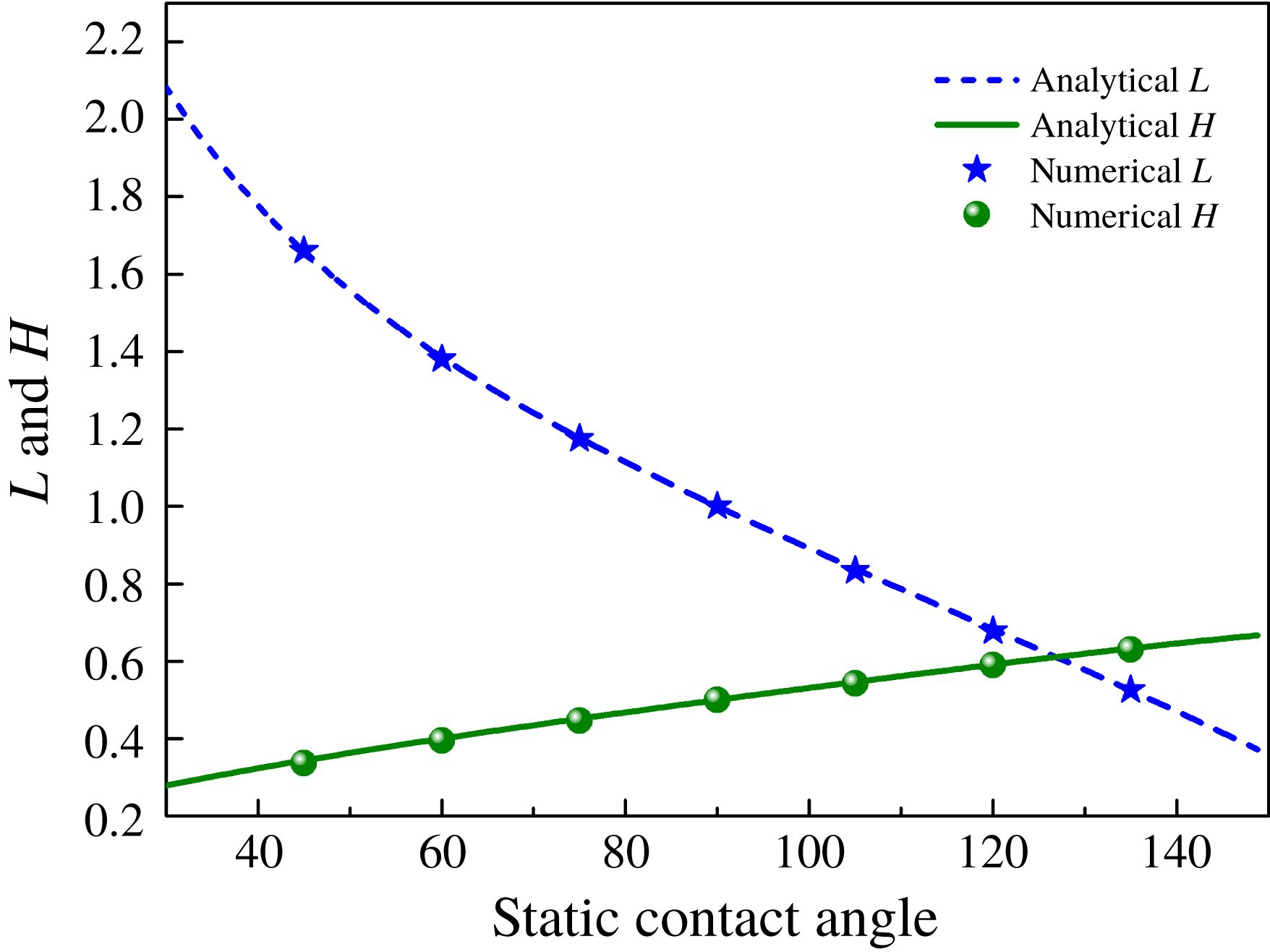
Reference Cai, Marschall, Wörner and Deutschmann2014):
 $$\begin{eqnarray}L=2R_{0}\sqrt{\frac{\unicode[STIX]{x03C0}}{2(\unicode[STIX]{x1D703}_{s}-\sin \unicode[STIX]{x1D703}_{s}\cos \unicode[STIX]{x1D703}_{s})}}\sin \unicode[STIX]{x1D703}_{s},\quad H=R_{0}\sqrt{\frac{\unicode[STIX]{x03C0}}{2(\unicode[STIX]{x1D703}_{s}-\sin \unicode[STIX]{x1D703}_{s}\cos \unicode[STIX]{x1D703}_{s})}}(1-\cos \unicode[STIX]{x1D703}_{s}).\end{eqnarray}$$
We conduct several simulations in a wide range of surface wettability for both hydrophilic and hydrophobic cases (
 $\unicode[STIX]{x1D703}_{s}$
varies from
 $45^{\circ }$
to
 $135^{\circ }$
). Analytical and numerical values of
 $L$
and
 $H$
are compared in figure 2, and a good agreement is observed for all values of
 $\unicode[STIX]{x1D703}_{s}$
.
Comparison of analytical and numerical values of spreading length
 $L$
and droplet height
 $H$
at different static contact angles
 $\unicode[STIX]{x1D703}_{s}$
. Here
 $\unicode[STIX]{x1D703}_{s}$
ranges from
 $45^{\circ }$
to
 $135^{\circ }$
with an interval
 $15^{\circ }$
.

To clearly demonstrate the effect of surfactants on the MCL, we compare the dynamics of clean and contaminated (with surfactants) droplets. The Langmuir adsorption constant
 $\unicode[STIX]{x1D713}_{c}$
and the parameter
 $Ex$
take values of 0.017 and 1, respectively, with the value of
 $Pi$
determined from (3.16). Other parameters are taken as before. Both hydrophilic (
 $\unicode[STIX]{x1D703}_{s}=60^{\circ }$
) and hydrophobic (
 $\unicode[STIX]{x1D703}_{s}=120^{\circ }$
) cases are considered in this study. For the contaminated droplet, the initialization of surfactant concentration is performed using the analytical prediction in (3.15) for
 $\unicode[STIX]{x1D713}$
with the initial surfactant bulk concentration
 $\unicode[STIX]{x1D713}_{b}=1.5\times 10^{-2}$
.
Profiles of (a) contaminated droplet at different times and (b) clean and contaminated droplets in equilibrium on a hydrophilic surface with static contact angle
 $\unicode[STIX]{x1D703}_{s}=60^{\circ }$
. For the contaminated droplet, the initial surfactant bulk concentration
 $\unicode[STIX]{x1D713}_{b}$
is
 $1.5\times 10^{-2}$
. In (b), equilibrium contact angles
 $\unicode[STIX]{x1D703}_{e}$
for clean and contaminated droplets are
 $60^{\circ }$
and
 $52^{\circ }$
, respectively.

Profiles of (a) contaminated droplet at different times and (b) clean and contaminated droplets in equilibrium on a hydrophobic surface with static contact angle
 $\unicode[STIX]{x1D703}_{s}=120^{\circ }$
. For the contaminated droplet, the initial surfactant bulk concentration
 $\unicode[STIX]{x1D713}_{b}$
is
 $1.5\times 10^{-2}$
. In (b), equilibrium contact angles for clean and contaminated droplets are
 $120^{\circ }$
and
 $129^{\circ }$
, respectively.

Figure 3(a) gives the evolution of a contaminated droplet on a hydrophilic surface at different times (t ranges from 0 to 10). The contaminated droplet constantly spreads until the steady state is reached. Equilibrium contact angles
 $\unicode[STIX]{x1D703}_{e}$
for clean and contaminated droplets in figure 3(b) are
 $60^{\circ }$
and
 $52^{\circ }$
, respectively. Obviously, the presence of surfactants makes the droplet more hydrophilic on a hydrophilic surface. In contrast to the hydrophilic surface, surfactants make the droplet more hydrophobic on a hydrophobic surface by increasing the equilibrium contact angle
 $\unicode[STIX]{x1D703}_{e}$
from
 $120^{\circ }$
to 129
 $^{\circ }$
, as shown in figure 4. Results in figures 3 and 4 are consistent with the results obtained for sharp interface models (Lai et al.
Reference Lai, Tseng and Huang2010; Xu & Ren Reference Xu and Ren2014; Zhang et al.
Reference Zhang, Xu and Ren2014). We further calculate the spreading length
 $L$
, the droplet height
 $H$
and
 $\unicode[STIX]{x1D703}_{e}$
for the contaminated droplet (
 $\unicode[STIX]{x1D713}_{b}=1.5\times 10^{-2}$
) in a wide range of surface wettability (
 $\unicode[STIX]{x1D703}_{s}$
varies from
 $45^{\circ }$
to
 $135^{\circ }$
). Analytical
 $L$
and
 $H$
for the clean droplet in figure 5 serve as a comparison. It is observed from figure 5 that the effect of surfactants is more obvious on the strong hydrophilic or hydrophobic surface. The inset gives
 $\unicode[STIX]{x1D703}_{e}$
of the contaminated droplet. The blue line in the inset represents static contact angles
 $\unicode[STIX]{x1D703}_{s}$
of the clean droplet (the slope of this line is 1), and it serves as a reference. We found that
 $\unicode[STIX]{x1D703}_{e}$
can be approximately predicted by
 $\unicode[STIX]{x1D703}_{s}$
through a linear relationship:
 $\unicode[STIX]{x1D703}_{e}=1.3\unicode[STIX]{x1D703}_{s}-25.7$
.
Numerical spreading length
 $L$
(points) and droplet height
 $H$
(points) for the contaminated droplet, and analytical values (lines) calculated from static contact angles serve as a comparison. For the contaminated droplet, the initial surfactant bulk concentration
 $\unicode[STIX]{x1D713}_{b}$
is
 $1.5\times 10^{-2}$
. The inset gives
 $\unicode[STIX]{x1D703}_{e}$
of the contaminated droplet. It can be observed that
 $\unicode[STIX]{x1D703}_{e}$
can be approximately predicted by
 $\unicode[STIX]{x1D703}_{s}$
through a linear relationship:
 $\unicode[STIX]{x1D703}_{e}=1.3\unicode[STIX]{x1D703}_{s}-25.7$
.

We also extend our work to a three-dimensional computational domain
 $[0,0.8]^{2}\times [0,0.4]$
. A grid size of
 $110^{2}\times 55$
and time step size
 $\unicode[STIX]{x1D6FF}t=8\times 10^{-4}$
are used in simulations. For the contaminated droplet, the initial surfactant bulk concentration
 $\unicode[STIX]{x1D713}_{b}$
is
 $2.5\times 10^{-2}$
. Results in figure 6 clearly demonstrate the effect of surfactants on the contact line dynamics. The presence of surfactants reduces
 $\unicode[STIX]{x1D703}_{e}$
from
 $60^{\circ }$
to
 $42^{\circ }$
on the hydrophilic surface, and increases
 $\unicode[STIX]{x1D703}_{e}$
from
 $120^{\circ }$
to
 $139^{\circ }$
on the hydrophobic surface.
Profiles of clean and contaminated droplets on (a) hydrophilic (
 $\unicode[STIX]{x1D703}_{s}=60^{\circ }$
) and (b) hydrophobic (
 $\unicode[STIX]{x1D703}_{s}=120^{\circ }$
) surfaces. For the contaminated droplet, the initial surfactant bulk concentration
 $\unicode[STIX]{x1D713}_{b}$
is
 $2.5\times 10^{-2}$
. The computation domain is
 $[0,0.8]^{2}\times [0,0.4]$
. We use a grid size of
 $110^{2}\times 55$
and time step size
 $\unicode[STIX]{x1D6FF}t=8\times 10^{-4}$
in simulations. In (a), equilibrium contact angles
 $\unicode[STIX]{x1D703}_{e}$
of clean and contaminated droplets are
 $60^{\circ }$
and
 $42^{\circ }$
, respectively. In (b), equilibrium contact angles
 $\unicode[STIX]{x1D703}_{e}$
of clean and contaminated droplets are
 $120^{\circ }$
and
 $139^{\circ }$
, respectively.

Evolutions of unbalanced Young stresses at right contact points of clean and contaminated droplets (
 $\unicode[STIX]{x1D713}_{b}=1.5\times 10^{-2}$
). The static contact angle
 $\unicode[STIX]{x1D703}_{s}$
of the hydrophilic surface is
 $60^{\circ }$
.

The Young equation can well explain the effect of surfactants on the droplet dynamics on the solid surface. As in Wang et al. (Reference Wang, Qian and Sheng2008), we can derive that
 $$\begin{eqnarray}\int _{int}[L\unicode[STIX]{x2202}_{\unicode[STIX]{x1D70F}}\unicode[STIX]{x1D719}]\,\text{d}\unicode[STIX]{x1D70F}=\int _{int}[\mathit{Cn}\unicode[STIX]{x2202}_{n}\unicode[STIX]{x1D719}\unicode[STIX]{x2202}_{\unicode[STIX]{x1D70F}}\unicode[STIX]{x1D719}+M^{\prime }(\unicode[STIX]{x1D719})\unicode[STIX]{x2202}_{\unicode[STIX]{x1D70F}}\unicode[STIX]{x1D719}]\,\text{d}\unicode[STIX]{x1D70F}=\unicode[STIX]{x1D70E}_{e}\cos \unicode[STIX]{x1D703}_{e}+\unicode[STIX]{x0394}\unicode[STIX]{x1D70E}_{fs},\end{eqnarray}$$
where
 $\int _{int}\text{d}\unicode[STIX]{x1D70F}$
denotes the integration across the fluid–fluid interface along the
 $\unicode[STIX]{x1D70F}$
-direction,
 $\unicode[STIX]{x0394}\unicode[STIX]{x1D70E}_{fs}$
is a function of the local composition at the solid surface measuring the fluid–solid interfacial free energy per unit area and
 $\unicode[STIX]{x1D70E}_{e}$
is the interfacial tension of a contaminated droplet in equilibrium. Equation (4.2) indicates that the unbalanced Young stress dominates the evolution of contact angle. It drives the droplet at two contact points to spread on a hydrophilic surface or to recoil on a hydrophobic surface. In equilibrium, the unbalanced Young stress decreases to zero (figure 7), namely
 $L=0$
, and (4.2) reduces to the classical Young equation
 $$\begin{eqnarray}\unicode[STIX]{x1D70E}_{e}\cos \unicode[STIX]{x1D703}_{e}+\unicode[STIX]{x0394}\unicode[STIX]{x1D70E}_{fs}=0.\end{eqnarray}$$
The boundary condition
 $\unicode[STIX]{x2202}_{n}\unicode[STIX]{x1D713}=0$
allows the presence of free surfactants on the fluid–solid interface, but these surfactants do not affect the fluid–solid interfacial tension through adsorption or the like, so clean and contaminated droplets have the same
 $\unicode[STIX]{x0394}\unicode[STIX]{x1D70E}_{fs}$
. Then we have
 $$\begin{eqnarray}\unicode[STIX]{x1D70E}_{e}\cos \unicode[STIX]{x1D703}_{e}=\unicode[STIX]{x1D70E}_{0}\cos \unicode[STIX]{x1D703}_{s},\end{eqnarray}$$
where
 $\unicode[STIX]{x1D70E}_{0}$
is the interfacial tension of a clean droplet. The addition of surfactants greatly reduces the interfacial tension between fluids, resulting in
 $\unicode[STIX]{x1D70E}_{e}<\unicode[STIX]{x1D70E}_{0}$
. We can derive that cos
 $\unicode[STIX]{x1D703}_{e}>\cos \unicode[STIX]{x1D703}_{s}$
from (4.4). Thus,
 $\unicode[STIX]{x1D703}_{e}$
is smaller than
 $\unicode[STIX]{x1D703}_{s}$
in the hydrophilic case (the contaminated droplet becomes more hydrophilic), and
 $\unicode[STIX]{x1D703}_{e}$
is larger than
 $\unicode[STIX]{x1D703}_{s}$
in the hydrophobic case (the contaminated droplet becomes more hydrophobic).
We denote the unbalanced Young stresses at right contact points of clean and contaminated droplets as
 $F_{Rc}$
and
 $F_{Rs}$
, respectively. Figure 7 gives evolutions of
 $F_{Rc}$
and
 $F_{Rs}$
, and the whole process can be divided into three stages. In the first stage, the contaminated droplet spreads faster than the clean droplet since
 $F_{Rs}$
is larger than
 $F_{Rc}$
. During the droplet spreading process, the unbalanced Young stress always drags the right contact point forward to reduce the contact angle, and it decreases as the contact angle changes until equilibrium. Thus, to some extent, the unbalanced Young stress can be reflected in the contact angle. Obviously, at the same moment, the contaminated droplet has a smaller contact angle than the clean droplet, which explains why the change in
 $F_{Rs}$
is more dramatic in the second stage. It can be observed that
 $F_{Rs}$
is larger than
 $F_{Rc}$
in the third stage, and this fact may account for a smaller equilibrium contact angle of the contaminated droplet.
The linear relationship between the interfacial tension lowering
 $\unicode[STIX]{x0394}\unicode[STIX]{x1D70E}/\unicode[STIX]{x1D70E}_{0}$
and
 $\ln (1-\unicode[STIX]{x1D713}_{0})$
. Fitted formulas of green and blue lines can be approximated as
 $\unicode[STIX]{x0394}\unicode[STIX]{x1D70E}/\unicode[STIX]{x1D70E}_{0}=0.3396\ln (1-\unicode[STIX]{x1D713}_{0})$
and
 $\unicode[STIX]{x0394}\unicode[STIX]{x1D70E}/\unicode[STIX]{x1D70E}_{0}=0.1942\ln (1-\unicode[STIX]{x1D713}_{0})$
, respectively. These results directly validate the equilibrium equation of state (3.18).

The interfacial tension lowering
 $\unicode[STIX]{x0394}\unicode[STIX]{x1D70E}$
of a contaminated droplet in equilibrium can be calculated from
 $$\begin{eqnarray}\unicode[STIX]{x0394}\unicode[STIX]{x1D70E}=\unicode[STIX]{x1D70E}_{e}-\unicode[STIX]{x1D70E}_{0}=\unicode[STIX]{x1D70E}_{0}\left(\frac{\cos \unicode[STIX]{x1D703}_{s}-\cos \unicode[STIX]{x1D703}_{e}}{\cos \unicode[STIX]{x1D703}_{e}}\right).\end{eqnarray}$$
Now we perform a series of numerical experiments to verify the linear relationship between
 $\unicode[STIX]{x0394}\unicode[STIX]{x1D70E}$
and ln(1–
 $\unicode[STIX]{x1D713}_{0}$
) analytically obtained in (3.18). Two different scenarios are considered in this study:
 $Ex=0.5$
and
 $Ex=1$
. In each scenario, we conduct simulations with different surfactant bulk concentrations, e.g.
 $\unicode[STIX]{x1D713}_{b}=1\times 10^{-2}$
,
 $1.5\times 10^{-2}$
and
 $2\times 10^{-2}$
. The static contact angle
 $\unicode[STIX]{x1D703}_{s}$
of the bottom surface is taken to be
 $60^{\circ }$
. From the resulting profile of surfactant concentration in equilibrium, the surfactant loading of interface
 $\unicode[STIX]{x1D713}_{0}$
can be directly obtained. The equilibrium contact angle
 $\unicode[STIX]{x1D703}_{e}$
can be easily calculated when the contaminated droplet reaches the steady state, and then we get the interfacial tension lowering
 $\unicode[STIX]{x0394}\unicode[STIX]{x1D70E}$
from (4.5). Obviously, there is a linear relationship between
 $\unicode[STIX]{x0394}\unicode[STIX]{x1D70E}$
and
 $\ln (1-\unicode[STIX]{x1D713}_{0})$
, as plotted in figure 8, which directly validates the equilibrium equation of state (3.18). We use linear formulas to fit simulated values at different
 $Ex$
, and fitted equations of green and blue lines can be approximated as
 $\unicode[STIX]{x0394}\unicode[STIX]{x1D70E}/\unicode[STIX]{x1D70E}_{0}=0.3396\ln (1-\unicode[STIX]{x1D713}_{0})$
and
 $\unicode[STIX]{x0394}\unicode[STIX]{x1D70E}/\unicode[STIX]{x1D70E}_{0}=0.1942\ln (1-\unicode[STIX]{x1D713}_{0})$
, respectively. It worth noting that
 $Ex$
plays an important role in reducing the interfacial tension, and its effect is more obvious at higher interfacial surfactant concentration. We infer, in the last part of § 3, that the coefficient
 $k$
is determined by
 $Ex$
for the given Langmuir adsorption constant
 $\unicode[STIX]{x1D713}_{c}$
and interfacial thickness
 $Cn$
. It can be observed that the slopes (
 $kPi$
) of two fitted curves in figure 8 equal
 $0.1942$
(
 $Ex=1$
) and
 $0.3396$
(
 $Ex=0.5$
), respectively. The dimensionless parameter
 $Pi$
can be calculated from (3.16). Then we can obtain that
 $k$
equals 1.05 and 1.11 for the cases of
 $Ex=1$
and
 $Ex=0.5$
, respectively. This result verifies our inference that
 $k$
depends on
 $Ex$
.
The relative interfacial tension
 $\unicode[STIX]{x1D70E}_{e}/\unicode[STIX]{x1D70E}_{0}$
at different surfactant bulk concentrations
 $\unicode[STIX]{x1D713}_{b}$
. The Langmuir adsorption constant
 $\unicode[STIX]{x1D713}_{c}$
is 0.017. The analytical equation (4.6) fits the simulated values very well.

Using the Langmuir isotherm in (3.15) and equilibrium equation of state (3.18), we obtain the relationship between the relative interfacial tension
 $\unicode[STIX]{x1D70E}_{e}/\unicode[STIX]{x1D70E}_{0}$
and surfactant bulk concentration
 $\unicode[STIX]{x1D713}_{b}$
:
 $$\begin{eqnarray}\frac{\unicode[STIX]{x1D70E}_{e}}{\unicode[STIX]{x1D70E}_{0}}=-\frac{kPi}{\unicode[STIX]{x1D70E}_{0}}\ln (\unicode[STIX]{x1D713}_{b}+\unicode[STIX]{x1D713}_{c})+\frac{kPi}{\unicode[STIX]{x1D70E}_{0}}\ln \unicode[STIX]{x1D713}_{c}+1,\end{eqnarray}$$
where the Langmuir adsorption constant
 $\unicode[STIX]{x1D713}_{c}$
is 0.017 in this study. It can be observed that (4.6) fits the simulated values very well in figure 9, indicating the correctness of the Langmuir isotherm and the equilibrium equation of state to some extent. Again, we can see that the coefficient
 $k$
is determined by
 $Ex$
.
4.2 Droplet dynamics on a chemically patterned surface
4.2.1 Phase diagram of flow states
Having validated the MCL model, we investigate the droplet dynamics with soluble surfactants on a chemically patterned surface. The computational domain is
 $\unicode[STIX]{x1D6FA}=[0,4]\times [0,1]$
with periodic boundary conditions applied on the horizontal direction, as shown in figure 10. Initially, a semicircular droplet with a radius of 0.5 is placed on the bottom surface with static contact angles
 $\unicode[STIX]{x1D703}_{1}$
(
 $\unicode[STIX]{x1D703}_{1}<90^{\circ }$
) for the hydrophilic A-type stripe and
 $\unicode[STIX]{x1D703}_{2}$
(
 $\unicode[STIX]{x1D703}_{2}>90^{\circ }$
) for the hydrophobic B-type stripe. The droplet centre is located at (1, 0). A constant body force along the horizontal direction is applied on the droplet. A grid size of
 $600\times 150$
and time step size
 $\unicode[STIX]{x1D6FF}t=5\times 10^{-4}$
are used in all simulations. The Reynolds number
 $Re$
and Péclet numbers
 $Pe_{\unicode[STIX]{x1D719}}$
and
 $Pe_{\unicode[STIX]{x1D713}}$
are taken as 20, 100 and 10, respectively. The value of Cahn number
 $Cn$
is 0.01. The relaxation parameter
 $Pe_{\mathit{s}}$
and slip length
 $L_{s}$
are set to 0.005 and 0.0038, respectively. Both density ratio
 $\unicode[STIX]{x1D706}_{\unicode[STIX]{x1D70C}}$
and viscosity ratio
 $\unicode[STIX]{x1D706}_{\unicode[STIX]{x1D708}}$
of the droplet to the surrounding fluid are 2. The initial surfactant bulk concentration
 $\unicode[STIX]{x1D713}_{b}$
is
 $1.5\times 10^{-2}$
. To clearly demonstrate the effect of surfactants, we compare the dynamics of clean and contaminated droplets.
Schematic of computation domain
 $\unicode[STIX]{x1D6FA}=[0,L]\times [0,H]$
. A semicircular droplet with a radius of
 $L/8$
is placed on a chemically patterned surface with static contact angles
 $\unicode[STIX]{x1D703}_{1}$
(
 $\unicode[STIX]{x1D703}_{1}<90^{\circ }$
) for the hydrophilic A-type stripe (black stripe) and
 $\unicode[STIX]{x1D703}_{2}$
(
 $\unicode[STIX]{x1D703}_{2}>90^{\circ }$
) for the hydrophobic B-type stripe (green stripe). The droplet centre is located at (
 $L/4,0$
). The droplet is pushed along the horizontal direction by a constant body force.

Dynamics of clean (blue) and contaminated (red) droplets on a chemically patterned surface with static contact angles
 $\unicode[STIX]{x1D703}_{1}=60^{\circ }$
for the A-type stripe (black stripe) and
 $\unicode[STIX]{x1D703}_{2}=120^{\circ }$
for the B-type stripe (green stripe). Droplets are pushed by a constant body force along the horizontal direction.

Evolution of the surfactant concentration for a contaminated droplet. The initial surfactant bulk concentration
 $\unicode[STIX]{x1D713}_{b}$
is
 $1.5\times 10^{-2}$
.

Figure 11 gives the evolution of droplets on a chemically patterned surface. At first, both clean and contaminated droplets spread out over the hydrophilic surface due to the unbalanced Young stress, and then move forward under the action of a constant body force (figure 11 b). After crossing the junction of wettability transition, both droplets suffer from large deformation and break up into daughter droplets. Obviously, compared with the clean droplet, the contaminated droplet has a larger advancing angle on the hydrophobic B-type stripe and a smaller receding angle on the hydrophilic A-type stripe (figure 11 c). We also note that the break-up of the contaminated droplet occurs earlier than that of the clean droplet (figure 11 d). After the break-up, the spreading droplets left on the hydrophobic stripe begin to contract (figure 11 e). Subsequently, daughter droplets detached from the solid surface move towards daughter droplets in contact with the B-type stripe (figure 11 f). As two clean daughter droplets approach each other, the film between them becomes very thin, and then they merge together due to the effect of interfacial tension. The merging droplet continues to slide on the hydrophilic A-type stripe (figure 11 j). While the thin film between two contaminated daughter droplets is always maintained at a certain thickness until they slide over each other (figure 11 h). Note that both contaminated daughter droplets eventually detach from the bottom surface. Figure 12 shows the evolution of surfactant concentration. The surfactant concentration around the interface is much larger than that for other regions, and the distribution of surfactants is non-uniform along the interface. In fact, the different behaviour between contaminated and clean droplets is caused by (1) the uniform reduction of interfacial tension and (2) the non-uniform effects from the non-uniform interfacial tension and the Marangoni stress along the interface. We also see that surfactants are swept into the bulk phases when concentration reaches a maximum at the droplet tip (figure 12 e). Figure 13 presents the evolutions of pressure field and surfactant concentration during the collision of two contaminated droplets. It can be observed that the pressure in the gap between two contaminated droplets increases significantly as they approach each other (point A to point C). The increasing pressure pushes surfactants away from the near-contact region, and the resulting Marangoni force acts as a repulsive force to prevent droplet coalescence (Liu & Zhang Reference Liu and Zhang2010; Wodlei et al. Reference Wodlei, Sebilleau, Magnaudet and Pimienta2018). The pressure in the gap decreases (point D to point E) as two contaminated droplets slide over each other.
Evolutions of (a) pressure field (background colour), (b) surfactant concentration and (c) pressure during the separation of two contaminated droplets. The initial surfactant bulk concentration
 $\unicode[STIX]{x1D713}_{b}$
is
 $1.5\times 10^{-2}$
.

There are several parameters that potentially influence the dynamics of a contaminated droplet on a chemically patterned surface, e.g. the surfactant bulk concentration
 $\unicode[STIX]{x1D713}_{b}$
, the defect strength
 $\unicode[STIX]{x0394}\unicode[STIX]{x1D703}_{e}=\unicode[STIX]{x1D703}_{2}-\unicode[STIX]{x1D703}_{1}$
, the Reynolds number
 $Re$
, etc. In this work, we only consider the effect of
 $\unicode[STIX]{x1D713}_{b}$
and
 $\unicode[STIX]{x0394}\unicode[STIX]{x1D703}_{e}$
on the behaviour of a contaminated droplet. A series of numerical simulations, with
 $\unicode[STIX]{x1D713}_{b}$
ranging from
 $1\times 10^{-3}$
to
 $1.5\times 10^{-2}$
and
 $\unicode[STIX]{x0394}\unicode[STIX]{x1D703}_{\mathit{e}}$
ranging from
 $20^{\circ }$
to
 $100^{\circ }$
, are conducted to obtain a clear understanding of the droplet dynamics. Other parameters and boundary conditions remain unchanged. Results demonstrate that all contaminated droplets at various conditions suffer from large deformation and break-up, just as in figure 11(c,d). After droplet break-up, we observe three typical flow states, specifically the coalescence mode, the non-coalescence mode and the detachment mode, as shown in figure 14. At low
 $\unicode[STIX]{x1D713}_{b}$
and medium
 $\unicode[STIX]{x0394}\unicode[STIX]{x1D703}_{e}$
(
 $\unicode[STIX]{x1D713}_{b}=1\times 10^{-3}$
and
 $\unicode[STIX]{x0394}\unicode[STIX]{x1D703}_{e}=70^{\circ }$
), the coalescence occurs as two contaminated droplets move towards each other because of the interfacial tension. At high
 $\unicode[STIX]{x1D713}_{b}$
and low
 $\unicode[STIX]{x0394}\unicode[STIX]{x1D703}_{e}$
(
 $\unicode[STIX]{x1D713}_{b}=1.5\times 10^{-2}$
and
 $\unicode[STIX]{x0394}\unicode[STIX]{x1D703}_{e}=50^{\circ }$
), the repulsive Marangoni force together with the low interfacial tension leads to the separation of two daughter droplets, and the droplet in contact with the bottom wall will continue to slide on the hydrophilic A-type stripe. This phenomenon is called ‘non-coalescence’. If we increase
 $\unicode[STIX]{x0394}\unicode[STIX]{x1D703}_{e}$
on the basis of the non-coalescence event (
 $\unicode[STIX]{x1D713}_{b}=1.5\times 10^{-2}$
and
 $\unicode[STIX]{x0394}\unicode[STIX]{x1D703}_{e}=70^{\circ }$
), the detachment event will occur, when the droplet sliding on the bottom wall (green stripe) leaves the patterned surface. Note that the droplet can only detach from the solid surface on the hydrophobic B-type stripe (green stripe).
Three typical flow states of contaminated droplets at various surfactant bulk concentrations
 $\unicode[STIX]{x1D713}_{b}$
and defect strengths
 $\unicode[STIX]{x0394}\unicode[STIX]{x1D703}_{e}$
: coalescence, non-coalescence and detachment. The A-type stripe (black stripe) with static contact angle
 $\unicode[STIX]{x1D703}_{1}$
is hydrophilic and the B-type stripe (green stripe) with static contact angle
 $\unicode[STIX]{x1D703}_{2}$
is hydrophobic. We define the defect strength
 $\unicode[STIX]{x0394}\unicode[STIX]{x1D703}_{e}$
as the difference of
 $\unicode[STIX]{x1D703}_{1}$
and
 $\unicode[STIX]{x1D703}_{2}$
, namely
 $\unicode[STIX]{x0394}\unicode[STIX]{x1D703}_{e}=\unicode[STIX]{x1D703}_{2}-\unicode[STIX]{x1D703}_{1}$
.

A phase diagram of flow states for contaminated droplets at different
 $\unicode[STIX]{x1D713}_{b}$
and
 $\unicode[STIX]{x0394}\unicode[STIX]{x1D703}_{e}$
is further shown in figure 15. A black star identifies a coalescence event, a red diamond marks a non-coalescence event and a blue circle represents a detachment event. As we can see, only non-coalescence occurs for all
 $\unicode[STIX]{x1D713}_{b}$
when
 $\unicode[STIX]{x0394}\unicode[STIX]{x1D703}_{e}$
is less than
 $60^{\circ }$
. The surfactant bulk concentration
 $\unicode[STIX]{x1D713}_{b}$
begins to affect the flow state of a droplet as the defect strength
 $\unicode[STIX]{x0394}\unicode[STIX]{x1D703}_{e}$
increases to
 $60^{\circ }$
. Detachment events occur at high
 $\unicode[STIX]{x1D713}_{b}$
since surfactants reduce the adsorption effect of the B-type stripe by increasing advancing contact angles of droplets. With a decrease of
 $\unicode[STIX]{x1D713}_{b}$
, droplets cannot detach from the B-type stripe due to the weak effect of surfactants, and non-coalescence phenomena appear. If we further reduce
 $\unicode[STIX]{x1D713}_{b}$
, a large interfacial tension will lead to the coalescence of two contaminated droplets. It can be observed that non-coalescence events occur on a narrower range of
 $\unicode[STIX]{x1D713}_{b}$
at
 $\unicode[STIX]{x0394}\unicode[STIX]{x1D703}_{e}=70^{\circ }$
and completely disappear when
 $\unicode[STIX]{x0394}\unicode[STIX]{x1D703}_{e}$
is larger than
 $70^{\circ }$
. Detachment and coalescence events dominate flow states of droplets at
 $\unicode[STIX]{x0394}\unicode[STIX]{x1D703}_{e}=80^{\circ }$
. Coalescence events only occur at specific surfactant bulk concentrations when
 $\unicode[STIX]{x0394}\unicode[STIX]{x1D703}_{e}$
is larger than
 $80^{\circ }$
. Overall, the non-coalescence event is the only flow state of contaminated droplets at low defect strength (
 $\unicode[STIX]{x0394}\unicode[STIX]{x1D703}_{e}\leqslant 50^{\circ }$
) and completely disappears at high defect strength (
 $\unicode[STIX]{x0394}\unicode[STIX]{x1D703}_{e}\geqslant 80^{\circ }$
). All three flow states occur at medium defect strength (
 $50^{\circ }<\unicode[STIX]{x0394}\unicode[STIX]{x1D703}_{e}<80^{\circ }$
). The detachment event dominates the flow behaviour of droplets at high defect strength.
A phase diagram of flow states for contaminated droplets at different surfactant bulk concentrations
 $\unicode[STIX]{x1D713}_{b}$
and defect strengths
 $\unicode[STIX]{x0394}\unicode[STIX]{x1D703}_{e}$
. A black star identifies a coalescence event, a red diamond marks a non-coalescence event and a blue circle represents a detachment event.

4.2.2 Unbalanced Young stress at the MCL
In this section, we focus on the evolution of the unbalanced Young stress
 $L\unicode[STIX]{x2202}_{\unicode[STIX]{x1D70F}}\unicode[STIX]{x1D719}$
when a contaminated droplet moves across the junction of wettability transition. As a contaminated droplet moves along the
 $x$
direction, the advancing contact angle and receding contact angle are denoted as
 $\unicode[STIX]{x1D703}_{A}$
and
 $\unicode[STIX]{x1D703}_{R}$
, respectively. Stresses
 $F_{A}$
and
 $F_{R}$
are unbalanced Young stresses acting on the triple-phase contact points A and R, respectively. As shown in figure 16, the unbalanced Young stress is defined as positive when it points from left to right; otherwise, it is defined as negative. We calculate unbalanced Young stresses
 $F_{A}$
and
 $F_{R}$
within the time range 0–2.8, and details of droplet dynamics in this period are depicted in figure 11(a–c). During the process, the triple-phase contact point A moves from the hydrophilic A-type stripe to the hydrophobic B-type stripe, while the point R never crosses the junction.
Illustration of unbalanced Young stresses
 $F_{A}$
and
 $F_{R}$
at the triple-phase contact points A and R. Angle
 $\unicode[STIX]{x1D703}_{A}$
is the advancing contact angle and
 $\unicode[STIX]{x1D703}_{R}$
is the receding contact angle.

Evolutions of unbalanced Young stresses (a)
 $F_{R}$
and (b)
 $F_{A}$
at different defect strengths
 $\unicode[STIX]{x0394}\unicode[STIX]{x1D703}_{e}$
. The initial surfactant bulk concentration
 $\unicode[STIX]{x1D713}_{b}$
is
 $1.5\times 10^{-2}$
.

The chemical potential
 $L$
in the unbalanced Young stress measures the deviation from the equilibrium condition (
 $L=0$
) at the solid surface, and the main role of the unbalanced Young stress is to adjust the droplet to its equilibrium condition (equilibrium contact angle
 $\unicode[STIX]{x1D703}_{e}$
). Figure 17 gives the evolutions of unbalanced Young stresses
 $F_{R}$
and
 $F_{A}$
. Initially, the static droplet (
 $\unicode[STIX]{x1D703}_{0}=90^{\circ }$
) spreads on the hydrophilic surface under the action of
 $F_{R}$
and
 $F_{A}$
. Stress
 $F_{R}$
points to the left (negative) and
 $F_{A}$
points in the opposite direction (positive). Both
 $F_{R}$
and
 $F_{A}$
decrease dramatically as
 $\unicode[STIX]{x1D703}_{R}$
and
 $\unicode[STIX]{x1D703}_{A}$
approach the equilibrium contact angle
 $\unicode[STIX]{x1D703}_{e}$
(
 $\unicode[STIX]{x1D703}_{e}<\unicode[STIX]{x1D703}_{s}$
on a hydrophilic surface). Meanwhile, the droplet keeps deforming as a constant body force drives it forward. The receding contact angle
 $\unicode[STIX]{x1D703}_{R}$
decreases with the deformation of the droplet, and
 $F_{R}$
becomes zero when
 $\unicode[STIX]{x1D703}_{R}$
decreases to
 $\unicode[STIX]{x1D703}_{e}$
, as shown in figure 17(a). The continuous deformation of the droplet causes the receding contact angle
 $\unicode[STIX]{x1D703}_{R}$
to continue to decrease (
 $\unicode[STIX]{x1D703}_{R}<\unicode[STIX]{x1D703}_{e}$
). In order to adjust the contact point R to the equilibrium condition,
 $F_{R}$
changes its direction (now it points to the right, positive) and pushes the contact point R to move forward. During the whole process, the contact point R never moves across the junction of wettability transition.
The evolution of
 $F_{A}$
is more complicated than that of
 $F_{R}$
. Before
 $\unicode[STIX]{x1D703}_{A}$
decreases to the equilibrium contact angle
 $\unicode[STIX]{x1D703}_{e}$
, droplet deformation leads to an increase of
 $\unicode[STIX]{x1D703}_{A}$
, which is contrary to the expectation of
 $F_{A}$
. Thus,
 $F_{A}$
begins to increase (point M in figure 17
b) and drags the contact point A forward to reduce
 $\unicode[STIX]{x1D703}_{A}$
. As the contact point A meets the junction,
 $F_{A}$
experiences a dramatic decrease (point N). According to the GNBC, the dectrease of
 $F_{A}$
must be accompanied by the decrease of fraction force due to the contact line slip. Thus, the classical phenomenon of the contact line sticking to the solid surface is expected to occur at the point N, and this is actually observed in figure 18.
Profiles of phase-field variable
 $\unicode[STIX]{x1D719}$
at different times. The initial surfactant bulk concentration
 $\unicode[STIX]{x1D713}_{b}$
is
 $1.5\times 10^{-2}$
.

In figure 17(b), we can see that the defect strength
 $\unicode[STIX]{x0394}\unicode[STIX]{x1D703}_{e}$
has a significant impact on the behaviour of
 $F_{A}$
. When the defect strength
 $\unicode[STIX]{x0394}\unicode[STIX]{x1D703}_{e}$
is less than
 $80^{\circ }$
,
 $\unicode[STIX]{x1D703}_{A}$
immediately arrives at the equilibrium contact angle
 $\unicode[STIX]{x1D703}_{e}$
of the hydrophobic B-type stripe. With droplet deformation,
 $\unicode[STIX]{x1D703}_{A}$
continues to increase and exceeds
 $\unicode[STIX]{x1D703}_{e}$
, and correspondingly
 $F_{A}$
increases to reduce
 $\unicode[STIX]{x1D703}_{A}$
. Throughout the whole process,
 $F_{A}$
never changes direction, and always drags the contact point A forward. The behaviour of
 $F_{A}$
becomes complicated when
 $\unicode[STIX]{x0394}\unicode[STIX]{x1D703}_{e}$
is larger than
 $80^{\circ }$
. As the droplet moves across the junction,
 $\unicode[STIX]{x1D703}_{A}$
(
 $\unicode[STIX]{x1D703}_{A}<90^{\circ }$
) is less than
 $\unicode[STIX]{x1D703}_{e}$
(
 $\unicode[STIX]{x1D703}_{e}>90^{\circ }$
on a hydrophobic surface). In order to adjust
 $\unicode[STIX]{x1D703}_{A}$
, the unbalanced Young stress
 $F_{A}$
, acting as the drag force before (positive), decreases dramatically and changes its direction (negative). Stress
 $F_{A}$
decreases to zero when
 $\unicode[STIX]{x1D703}_{A}$
arrives at
 $\unicode[STIX]{x1D703}_{e}$
, and it becomes the drag force again as
 $\unicode[STIX]{x1D703}_{A}$
exceeds
 $\unicode[STIX]{x1D703}_{e}$
with droplet deformation. Based on the above analysis, we can conclude that the unbalanced Young stress could be a driving or resistance force, which is determined by the critical defect strength
 $\unicode[STIX]{x0394}\unicode[STIX]{x1D703}_{e}$
, and
 $\unicode[STIX]{x0394}\unicode[STIX]{x1D703}_{e}$
is between
 $60^{\circ }$
and
 $80^{\circ }$
.
5 Conclusions
In this work, we present a derivation of the phase-field MCL model with soluble surfactants through the first law of thermodynamics, associated thermodynamic relations and the Onsager variational principle. The derived thermodynamically consistent model consists of two Cahn–Hilliard type of equations governing the evolution of interface and surfactant concentration, the incompressible Navier–Stokes equations and the GNBC for the MCL. With chemical potentials derived from the free energy functional, we analytically obtain certain equilibrium properties of surfactant adsorption, including equilibrium profiles for phase-field variables, the Langmuir isotherm and the equilibrium equation of state. A classical droplet spread case is used to numerically validate the MCL model and equilibrium properties of surfactant adsorption. The influence of surfactants on the contact line dynamics observed in our simulations is consistent with the results obtained using sharp interface models. Numerical results also demonstrate that the equilibrium contact angle of a contaminated droplet can be approximately predicted by the static contact angle of a clean droplet through a linear relationship. Using the proposed model, we investigate the droplet dynamics with soluble surfactants on a chemically patterned surface. It is observed that droplets will form three typical flow states as a result of different surfactant bulk concentrations and defect strengths, specifically the coalescence mode, the non-coalescence mode and the detachment mode. In addition, a phase diagram for the three flow states is presented. Finally, we study the unbalanced Young stress acting on triple-phase contact points. The unbalanced Young stress could be a driving or resistance force, which is determined by the critical defect strength.
Acknowledgements
G.Z. and J.K. contributed equally to this study. We are grateful to all reviewers for their constructive suggestions and comments. J.Y. and G.Z. acknowledge the support of the National Science and Technology Major Project (2016ZX05011-001), the Natural Science Foundation of China (51804325, 51674280 and 51774317) and Shandong Provincial Natural Science Foundation (ZR2019JQ21). The work of S.S. and J.K. is supported by the KAUST research fund awarded to the Computational Transport Phenomena Laboratory through grant BAS/1/1351-01-01.