The heat-assisted magnetic recording hot zone
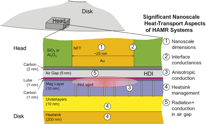
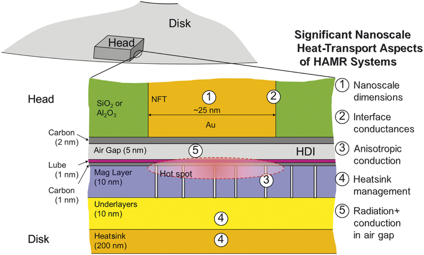
In a heat-assisted magnetic recording (HAMR) system, a metallic near-field optical transducer delivers highly localized optical energy to a magnetic medium, where it is absorbed as heat via ohmic dissipation, raising the temperature of the medium, typically 400–500°C above its Curie temperature. The near-field optical transducer also gets hot because it is lossy. Thus, we designate the near-field transducer (NFT), the adjacent medium, and air gap as the “hot zone” in the recording system. Figure 1 shows this region, drawn approximately to scale, and identifies some of the nanoscale heat-transfer issues, which are addressed in this article, that must be considered to analyze and design heat-assisted magnetic recording systems.
The heat-assisted magnetic recording (HAMR) hot zone and some of the main nanoscale thermal considerations that must be included in the analysis and design for HAMR systems. Note: HDI, head–disk interface; NFT, near-field transducer.
Nanoscale heat-transfer issues relevant to HAMR
Heat conduction is the primary heat-transfer process in HAMR. Macroscopically, heat conduction in diffusive regimes is described by the heat diffusion equation and Fourier’s Law, which relate the heat flux ( $\bar{q}$) (W m–2) to the temperature gradient (∇T) (K m–1) by the thermal conductivity (k) (W m–1 K–1),
 $$\bar{q} = - k\nabla T$$.
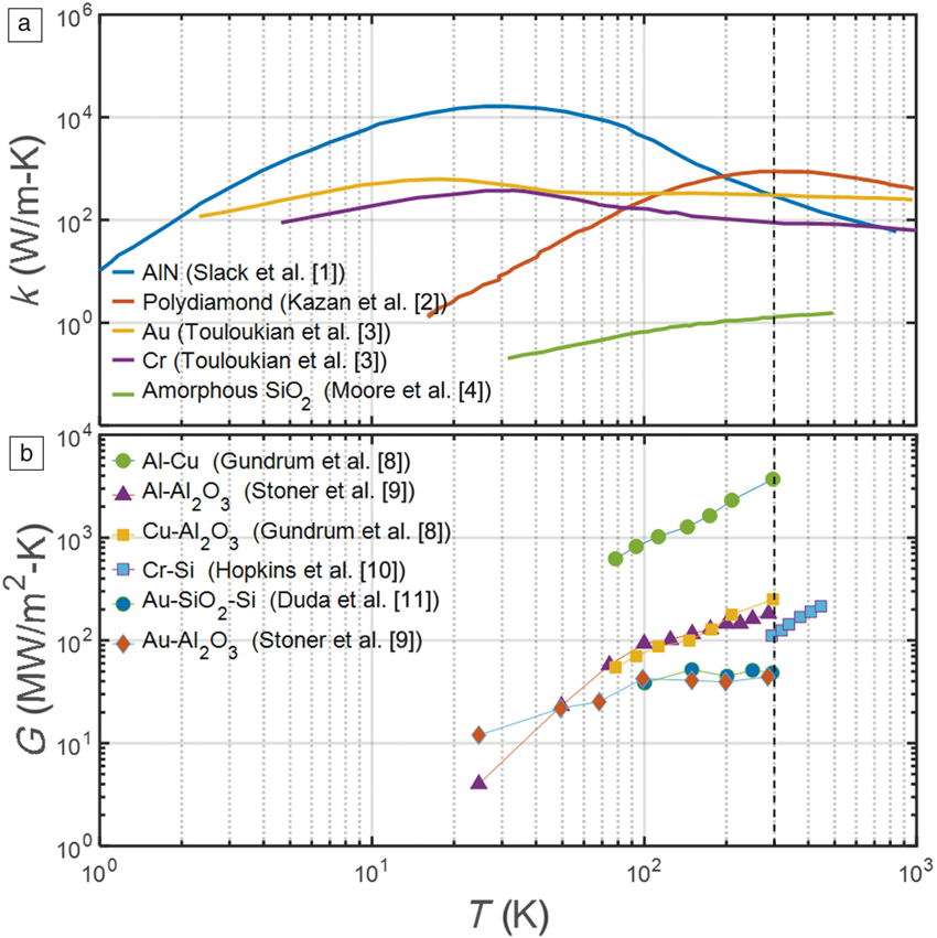
A wide range of thermal conductivities exists within a HAMR device at room temperature, ranging from ∼10–1 W m–1 K–1 for the organic lubricants, to ∼100 W m–1 K–1 for the amorphous SiO2 and Al2O3 head components, to ∼101 W m–1 K–1 for a metal alloy such as FePt, and to ∼102 W m–1 K–1 for metals such as Au. Heat conduction at elevated temperatures is critical to the operation of HAMR. The variation of k with T is shown in Figure 2a for several HAMR relevant materials.Reference Slack, Tanzilli, Pohl and Vandersande1–Reference Moore and Shi4 More generally, in an anisotropic medium, Fourier’s Law can be expressed based on a thermal conductivity tensor. While HAMR media are anisotropic, the full tensor description can be simplified because the thermal conductivities differ in the in-plane (r) and cross-plane (z) directions, which are also the two principal directions of heat propagation,
 $${q_r} = - {k_r}{{dT} \over {dr}}{\rm{\ and\ }}{q_z} = - {k_z}{{dT} \over {dz}}$$.
The implications and utility of this anisotropy for the operation of HAMR will be discussed in the section on media.
(a) Thermal conductivities, k, of various heat-assisted magnetic recording (HAMR) materials as a function of temperature, T. (b) Conductances, G, for HAMR material pairings as a function of temperature T.

While Fourier’s Law is applicable within a given material, at an interface between two materials the heat flux (designated as q z to indicate that it is normal to the interface) is related to the temperature jump (ΔT) (K) across the interface by the thermal interface conductance (G) (W m–2K–1),
 $${q_z} = G{\rm{\Delta }}T$$.
G is the reciprocal of the Kapitza resistance, which is a measure of an interface’s resistance to heat transfer and is named for P. Kapitza, who performed early experiments on thermal resistance of interfaces between liquid helium and various solids.Reference Kapitza5,Reference Kapitza6 The Kapitza length (lK) is a useful construct by which we can understand the importance of the interface, where we consider the thickness of material that generates the equivalent thermal resistance of the interface,
 $${l_K} = k/G$$.
Typical thermal interface conductances span ∼103 MW m–2K–1 for metal–metal interfaces to ∼102 MW m–2K–1 for common metal dielectric interfaces, and as low as ∼50 MW m–2K–1 for Au–dielectric interfaces.Reference Lyeo and Cahill7,Reference Gundrum, Cahill and Averback8 This results in lK of 1−25 nm when based upon SiO2 (k = 1.3 W/m-K), and 0.3–6 μm when based upon Au (k = 300 W/m-K). Hence, when features and interfaces are spaced by tens of nanometers, as they are in both the HAMR head and media, G plays a profound role in defining temperature. Values of G for material pairings representative of those found in HAMR devices, are plotted as a function of temperature in Figure 2b.Reference Gundrum, Cahill and Averback8–Reference Duda, Yang, Foley, Cheaito, Medlin, Jones and Hopkin11
The macroscopic description of heat diffusion is subject to values of k and G that stem from phonons and electrons—the fundamental energy carriers that transport and store heat. Heat-conduction processes in both the head and media are dominated by phonons and electrons, while the head–media interaction may also be influenced by radiative heat transfer by photons. The contribution of a phonon to thermal conductivity is the product of its group velocity (vg) (m/s), heat capacity, and mean free path (Λp) (i.e., the average distance it travels between collisions [m]). A summation of their contributions over all phonon frequencies and directions yields the phonon thermal conductivity kp. The approximation,
 $${k_p} = {1 \over 3}{C_p}{\bar{v}_g}{{\rm{\bar{\Lambda }}}_p}$$,
is often used, where C p is the total volumetric heat capacity (J K–1 m–3) due to phonons and  ${\bar{v}_g}$ and
 ${{\rm{\bar{\Lambda }}}_p}$ are averages over all phonons.
In typical small unit cell crystalline materials, acoustic phonons, which arise from vibrational modes where adjacent atoms oscillate in-phase, dominate thermal transport and move at group velocities well approximated by the speed of sound, v s (m s–1). In crystalline solids, Λp can span several orders of magnitude. For example, in Si, approximately 90% of the thermal conductivity comes from phonons in the range 10 nm < Λp < 10,000 nm at room temperature.Reference Regner, Freedman and Malen12 Size effects suppress kp when boundaries cause reductions in Λp relative to the intrinsic mean free path distributions set by phonon–phonon and impurity scattering in an infinite crystal.
Amorphous solids lack long-range periodicity and hence are not aptly described by the phonon model. Simple descriptions of thermal conductivity in amorphous materials are offered by the Einstein model and the Cahill–Pohl model, both of which ascribe short mean free paths to the vibrations that carry energy within amorphous solids.Reference Cahill, Watson and Pohl13 For example, the Cahill–Pohl model suggests that energy carriers are phonon-like, with mean free paths similar in magnitude to their wavelengths. By comparison, mean free paths are 102–104× phonon wavelengths in crystals at room temperature. Recent evidence suggests the presence of phonon-like states in select amorphous materials (e.g., a-SiReference Larkin and McGaughey14), but typical amorphous materials have low thermal conductivities, which are less affected by scaling dimensions.
Thermal transport in HAMR metals is dominated by free electrons. Like phonons, the electronic thermal conductivity ke can be defined as a product of heat capacity, group velocity, and mean free path as
 $${k_e} = {1 \over 3}{C_e}{v_F}{{\rm{\Lambda }}_e}$$,
where C e is the volumetric electronic heat capacity (J K–1 m–3), v F (m s–1) is the Fermi velocity, and Λe is the electron mean free path. Since thermal electrons are fermions that exist over a narrow range of energies, the values of velocity and mean free path are approximately defined at the Fermi energy, and averages are unnecessary. The electronic thermal conductivity is closely related to the electrical conductivity, σ, (Ω–1 m–1) by the Weidemann–Franz (WF) Law because free electrons carry both heat and charge. The WF Law is stated as k e = σ L T, where L is the Lorentz number and has a value of L = 2.44 × 10⁻⁸ W Ω K–2 and T is temperature (K).Reference Ashcroft and Mermin15 For high-conductivity metals such as Au and Ag, Λe ∼ 50 nm. Nano-sized grains and features below this scale, as can exist in HAMR heads, suppress k e. Phonons contribute in parallel with electrons to the metal’s thermal conductivity (i.e., k = ke + kp), but since C e/C p ∼ 10–2, v F/v s ∼ 103 and  ${{\rm{\Lambda }}_e}/{{\rm{\bar{\Lambda }}}_p}$ ∼ 100 (for metals such as Au and Ag), the phonon contribution is negligible at room temperature (e.g., in the case of Au, ke = 307 W m–1 K–1, while kp = 3.3 W m–1 K–1).Reference Jain and McGaughey16
Despite their negligible role in carrying heat in metals, phonons scatter electrons and play a role in transient processes as they are key to storing heat; at interfaces with dielectrics, they can transmit energy that electrons cannot. At the small length- and time scales important to HAMR, it is possible for electrons and phonons to be out of equilibrium with one another. This is typically described using two-temperature models whereby the electron population at Te and the phonon population at Tp exchange heat at a rate of g(Te–Tp), where g is the electron–phonon coupling parameter (W m–3 K–1).Reference Wang and Cahill17 The electron–phonon coupling parameter is low in plasmonic metals such as Au (2.8 × 10¹⁶ W m–3 K–1 at T = 300 K17), which enables large Λe relative to other metals (by comparison gPt is 40 × gAu),Reference Lin, Zhigilei and Celli18 but results in a nonequilibrium condition that can impact heat dissipation. As a result, the characteristic length scale for electron–phonon equilibration is  $\sqrt {{k_e}/g}$, which is ∼102 nm in Au.Reference Wang and Cahill17 This implies that electrons heated due to plasmonic dissipation in the HAMR head will be locally out of equilibrium with the phonons. Due to the higher g of Fe and Pt, such length scales are anticipated to be far shorter in the alloys used for HAMR media.
Interfaces play a key role in heat dissipation within both the HAMR head and media. Metal–metal, dielectric–dielectric, and metal–dielectric interfaces are present. Efficient electron transmission at metal–metal interfaces dominates parallel phonon processes, leading to G e ∼ 103 MW m–2 K–1 (the electronic contribution to interface conductance), while less efficient phonon transmission dominates dielectric–dielectric interfaces leading to a phonon contribution of G p ∼ 102 MW m–2 K–1.Reference Lyeo and Cahill7,Reference Gundrum, Cahill and Averback8 Within the head, heat from plasmonic heating of Au must be dissipated into the surrounding dielectric across a critical interface. Transmission of heat across a metal–dielectric interface can be modeled as a two-step process:Reference Majumdar and Reddy19 (1) electrons in the metal transfer heat to phonons in the metal, and (2) phonons in the metal transmit into the dielectric. Step (1) thus creates an additional series thermal conductance that can be approximated as  ${G_{e - p}} = \sqrt {g{k_p}}$, which is then added to Gp from step (2) to create an effective conductance at the interface of G eff = G e–pG p/ (G e–p + G p). For Au, G e–p is approximately 300 MW m–2 K–1, which is far larger (∼5×) than G p for Au with relevant dielectrics such as SiO2 and Al2O3. More generally, Gp is the lesser of the two conductances and can vary appreciably depending on the materials at the interface. Thus, we provide an additional theoretical foundation for the behavior of the interface as a function of the properties of the materials on either side of the interface.
A phonon originating from material 1 contributes to G p based on the product of its group velocity, heat capacity, and the probability that it will transmit across the interface into material 2 (i.e., the transmission coefficient, ζ12). A summation of their contributions over all phonon frequencies and directions yields Gp. Similar to Equation 5 for k p, the approximation,
 $${G_p} = {1 \over 4}{C_{p,1}}{\bar{v}_{g,1}}{{\rm{\bar{\zeta }}}_{12}}$$,
can be used when acoustic phonons dominate Gp, where  ${{\rm{\bar{\zeta }}}_{12}}$ is the average transmission coefficient over all phonons originating in material 1. There is no consensus approach to defining ζ12, but an upper limit can be set by assuming
 ${{\rm{\bar{\zeta }}}_{12}} = 1$ for all phonons originating from the side of lesser
 ${C_p}{\bar{v}_g}$, which is known as the maximum transmission limit.Reference Monachon, Weber and Dames20 The diffuse mismatch model (DMM) is a model commonly used to estimate ζ12. The main assumption of the DMM is that all of the incident phonons will scatter elastically (i.e., without changing frequency) and diffusely at the interface, irrespective of the interface details. In other words, they will lose “memory” of their origins (in terms of direction) once they reach the interface.Reference Swartz and Pohl21,Reference Duda, Beechem, Smoyer, Norris and Hopkins22 According to the DMM, greater overlap in the phonon density of states between two materials leads to a higher value of ζ12, and thus a higher value of Gp. This will be applied to some specific interfaces discussed next.
Heat transfer across the nanoscale gap between head and media also play a role in the head–media interaction. High temperatures in the head may be caused by unintended “backheating” of the head by the media. Conduction through the airgap is one possible mechanism, but near-field radiative heat transfer cannot be ruled out. High Knudsen number regimes make gas conduction ballistic, with a conductance range of 103 < G < 107 W m–2 K–1, depending on the pressure and temperature in the gap. (The Knudsen number is the ratio of the mean free path to the dimension of the system). Blackbody radiation exchange by Planck’s Law of blackbody radiation would suggest radiative conductances in the range of 101 < Grad < 102 W m–2 K–1, but this does not consider enhancements to radiative exchange that occur when surfaces are spaced at wavelengths comparable to the peak radiation wavelength. In this case, evanescent modes, which decay exponentially from the surfaces, can overlap and thus enable huge enhancements, leading to near-field radiative conductances of 104 < G rad < 105 for 10-nm gaps at room temperature (smaller gaps and higher temperatures increase G rad).Reference Song, Fiorino, Meyhofer and Reddy23 While such high conductances have only been experimentally demonstrated with specific materials, experiments and theory are now in place to move forward with HAMR relevant pairings.
Heat transport in the head
The NFT in the HAMR head can itself be a source of heat that will raise the NFT temperature. This unnecessary yet inevitable heating of the NFT is problematic because the thermal expansion of the NFT closes the air gap between the media surface and the NFT, though this can be managed with appropriate design. Moreover, when optical resonances are exploited within the NFT, heating shifts these resonances, making coupling efficiency poor and unstable.Reference Zhou, Xu, Hammack, Stipe, Gao, Scholz and Gage24 Finally, undesired nanostructural evolution of the NFT (both materials and overall shape) can occur in response to this heating, which will compromise NFT function.
The primary NFT heating mechanisms occur through optical absorption in the NFT itself as it localizes optical power intended for the medium. According to thermal modeling results, depending on the power absorbed by the NFT, its temperature could rise from as low as 100°C to as high as 600°C.Reference Xu, Cen, Goh, Li, Toh, Zhang, Ye and Quan25 To analyze this temperature rise in heads, the concept of thermal resistance, R th, (K W–1) is used. It is defined, in analogy to electrical resistance in Ohm’s Law, as the temperature rise ΔT (K) per unit of absorbed thermal power Pth (W)
 $${R_{th}} = {\rm{\Delta }}T/{P_{th}}$$.
Accordingly, the temperature rise in the medium, ΔT med, relative to the temperature rise in the NFT, ΔT NFT, is given by the following ratio, which is taken as a the temperature ratio figure of merit
 $${{\Delta {T_{med}}} \over {\Delta {T_{NFT}}}} = {{{R_{th,med}}} \over {{R_{th,NFT}}}}{{{P_{th,med}}} \over {{P_{th,NFT}}}}$$ ,
where the subscripts indicate where the thermal powers are absorbed, medium versus NFT. Typically, power absorbed by the NFT is several times the power absorbed in the medium, which can be understood by recognizing that the NFT has a significantly larger volume and is exposed to a larger exciting field than the medium. Moreover, the nominally low-loss plasmonic Au has a larger skin depth, which tends to increase the absorbing volume and offset the lower loss in terms of total power absorbed.
A desirable value for the temperature ratio figure of merit discussed in the preceding paragraph is 5–10 or greater, such that the medium can be raised by ∼500°C (i.e., to its Curie temperature) while the head only heats up by 50–100°C. This means that thermal resistance of the NFT should be more than an order of magnitude smaller than that of the medium. Even so, for such modest temperature rises of the NFT, pure Au tends to be susceptible to degradation, so other materials with better thermal stability are sought. These other materials, however, typically perform more poorly on the temperature ratio figure of merit, because they dissipate more power and conduct heat more poorly than pure Au. Thus, a tradeoff must be considered. Blaber et al.Reference Blaber, Arnold and Ford26 discuss this in detail in a review article.
The thermal resistance of the medium will be discussed in the section on media. An estimate of the thermal resistance for the NFT body itself, R th,NFT,body, can be made based on the assumption that the significant amount of optical absorption for the head occurs in the tip of the NFT (in the form of a cone structure),Reference Bhargava and Yablonovitch27 giving
 $${R_{th,NFT,\,body}} = 1/\left( {{{\rm{\Omega }}_{NFT}}{k_{NFT}}{r_{min}}} \right)$$,
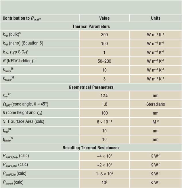
where ΩNFT is the solid angle of the NFT cone, k NFT is the thermal conductivity of the NFT material, and r min is the minimum radius of the NFT cone. Typical numbers for an NFT are shown for a cone with a 45° angle (r min= 12.5 nm) in Table I. They yield R th,NFT,body = ∼4 × 10⁵ K W–1, assuming thermal conductivity for nanoscale Au of 100 W m–1 K–1. This is lower than that for bulk Au (∼300 W m–1 K–1) due to grain sizes limiting Λe and thus ke through Equation 6. However, we must also consider the dissipation of heat into the dielectric cladding, which represents an additional thermal resistance in series. For an effective NFT radius, r eff, of 100 nm and hemispherical conduction (Ω = 2π steradians) into semi-infinite cladding of kclad = 1 W m–1 K–1, this amounts to R th,NFT,clad = ∼2 × 10⁶ K W–1, which is almost an order of magnitude larger than our conservative estimate of R th,NFT,body, such that this latter term will dominate the heat dissipation.Reference Bhargava and Yablonovitch27
Thermal and geometrical contributions to near-field transducer (NFT) and medium thermal resistances.

If the cladding material thermal conductivity could be increased by a factor of 10 or even 100, then R th,NFT,clad would drop to 2 × 10⁵ K W–1 or even 2 × 10⁴ K W–1. It would then no longer be the dominant thermal resistance in the determination of ΔT NFT. High thermal conductivity dielectrics with acceptable optical properties such as AlNReference Slack, Tanzilli, Pohl and Vandersande1 and diamondReference Kazan and Volz2 offer this possibility, although process integration of these materials is not straightforward, and their tribo-chemical behavior at the head–disk interface must be evaluated. Furthermore, textbook values of k for AlN and diamond rely upon significant contributions from long mean free path phonons (e.g., in AlN, phonons with Λp > 2500 nm contribute more than 50% of kp), that will be suppressed if grain sizes are small.Reference Freedman, Leach, Preble, Sitar, Davis and Malen28
Finally, the thermal interface resistance between the NFT metallic body and the surrounding dielectric must also be considered as a series thermal resistance R th,int = 1/GA Au, where AAu is the Au-clad interfacial area. If we use the typical value for an Au–dielectric interface, 50 MW m–2 K–1, as shown in Table I, this thermal resistance is 2 × 10⁵ K W–1, about 10% of R th,NFT,clad for a conventional low k cladding. If the cladding k were dramatically increased, it would then be desirable to reduce R th,NFT,int as the next largest impediment to heat dissipation from the head. According to the DMM introduced in the previous section, greater overlap in the density of states between two materials leads to a higher value of ζ12, and thus G.Reference Swartz and Pohl21,Reference Duda, Beechem, Smoyer, Norris and Hopkins22,Reference Jeong, Freedman, Liang, Chow, Sokalski, Bain and Malen29,Reference Duda, Smoyer, Norris and Hopkins30
There has been an experimental attemptReference Stevens, Smith and Norris31 to enhance G following this notion by inserting thin metal adhesion layers (less than 10 nm) such as Cr or Cu between Au and Al2O3 because they have a better Debye temperature match with the Al2O3 than Au. Similar Debye temperatures in different materials indicate better overlap in their phonon density of states, and thus better metal–dielectric thermal interface conductance, while the additional metal–metal interface has an order of magnitude larger conductance.Reference Stoner and Maris9,Reference Stevens, Smith and Norris31,Reference English, Duda, Smoyer, Jordan, Norris and Zhigilei32 In addition, there have been studies utilizing adhesion layers for improved thermal stability.Reference Ji, Xu, Cen, Ying and Toh33 Co-optimizing such adhesion layers for optical compatibility and chemical stability is an important future direction.
Heat transport in the medium
The NFT locally heats the medium close to or above the Curie temperature, T C, nanoseconds before the writing process.Reference Kryder, Gage, McDaniel, Challener, Rottmayer, Ju, Hsia and Erden34 Ideally, the thermal hot spot generated in the medium should be comparable to the optical spot, rather than a smeared out or broadened version that will inadvertently write on adjacent magnetic domains (which is undesirable). This produces the greatest lateral thermal gradients and affords the highest recording density. An enlarged medium hot spot indicates a preferential heat-transfer pathway laterally due to reduced in-plane thermal resistance. Li et al. demonstrated a reduction in media spot size characterized by a 40% reduction in curvature and a 56% increase in thermal gradient by replacing low thermal conductivity heat sink and interlayer materials with high thermal conductivity materials, thus reducing cross-plane thermal resistance.Reference Li, Chen, Rea, Blaber, Zhou, Zhou and Yin35
To prevent spreading of the thermal spot in the medium, the cross-plane or vertical heat transport must dominate the lateral diffusion of heat as well as the lateral transport of heat caused by the motion of the medium (i.e., advection of heat). Simple estimates of these three thermal conductances are possible.
The advective conductance can be estimated from the linear disk speed, v, and volumetric heat capacity, C v, of the magnetic medium. Assuming v is 10 m–1 s and C v is 3 MJ m–3 K–1, the corresponding conductance is ∼30 MW m–2 K–1.Reference Jubert, Zong and Grobis36 Assuming an area for this heat flux of 250 nm2 (trackwidth × medium thickness) and a temperature rise of 500 K gives a heat transfer rate of ∼4 μW. This number sets the scale for conductive heat transfer perpendicular to the medium, which must be an order of magnitude larger in order to avoid smearing of the hot spot by the disk motion. This advective smear prevents system designers from raising the thermal resistance of the medium to an arbitrarily large value to reduce power requirements and improve medium heating efficiency.
In support of this heuristic, the cross-plane and in-plane conductances are estimated to be ∼850 MW m–2 K–1 and ∼330 MW m–2 K–1, respectively,Reference Li, Chen, Rea, Blaber, Zhou, Zhou and Yin35 in studies aimed at NFT optimization, implying that ∼72% of the heat contained within the media hot spot will travel vertically through the media stack. Assuming respective areas of ∼500 nm2 (spot area) and 800 nmReference Kazan and Volz2 (spot perimeter × medium thickness), this gives heat flows of 210 μW and 130 μW, respectively. While these are both large compared to the advective flow, the lateral conduction is still a significant fraction of the vertical conduction, and there is a desire to minimize this lateral flow as much as possible.
Introducing anisotropy in the thermal conductivity of the medium is one way in which this contrast between vertical (cross-plane) and lateral (in-plane) heat flow is enhanced. This anisotropy is defined as the ratio of cross-plane to in-plane thermal conductivity. Measuring in-plane thermal conductivity is a challenging process, especially for highly anisotropic materials in which cross-plane thermal conductivity dominates measurements.Reference Feser and Cahill37 This challenge can be sidestepped by fabricating model systems that avoid parallel thermal conduction pathways. Ho et al. measured vertical heat conduction in FePt stacks with an amorphous C segregant using frequency domain thermoreflectance (FDTR).Reference Ho, Sharma, Ong, Malen, Bain and Zhu38 FDTR resultsReference Cahill39 indicate that FePt-C granular media with a 14.5-nm grain size exhibit anisotropy of around five with a cross-plane thermal conductivity of around 8 W/m-K. Further grain-size reduction is expected to further increase anisotropy, limiting lateral heat transfer during the writing process.Reference Ho, Sharma, Ong, Malen, Bain and Zhu38
The previously mentioned numbers can be used to estimate the overall medium thermal resistance and compare it to the NFT thermal resistance to examine relative heating levels. If vertical transport dominates, then a simple estimate of the thermal resistance of the medium, R th,med and underlayer stack can be made according to
 $${R_{th,med}} = \left( {{t_{med}}/{k_{med,z}} + {t_{UL}}/{k_{UL}}} \right)/\left( {{\rm{\pi \ }}r_{min}^2} \right)$$ ,
which assumes one-dimensional heat flow, where t med and t UL are the thicknesses of the medium and the underlayer, respectively, and k med,z and k UL are the thermal conductivities of the medium (cross-plane) and the underlayer, respectively. The radius of the hot spot is again r min. For typical values in Table I, this comes out to be ∼107 K/W. Thus 66 μW must be absorbed by the medium to raise its temperature by 500 K, which would be a typical operating point for HAMR. This value of medium thermal resistance is larger than NFT thermal resistance previously computed, but only by a factor of 2–5, which is not the factor of 10–20 sought by designers.
Finally, the issue of so-called “backheating” of the NFT by heat that flows from the hot medium across the air gap back to the NFT, has been raised in the literature. Both conduction and near-field radiation must be considered. An upper bound on the gap conductance associated with these mechanisms, per the discussion in the initial sections of this article, is 107 W m–2 K–1. For temperature differences of 500 K and areas associated with the hot spot (r min), this would give a heat flux of 2.5 μW, which will not cause significant heating of the NFT. However, given the small amount of experimental evidence and the uncertainty in the area over which this phenomenon might operate, more investigation of this heat path is needed to rule it out as a significant contributor to NFT temperature rise.
Summary
From the previous discussions of fundamental heat-transport mechanisms and the specific values and topologies of the NFT, medium and head–disk interface, the constraints and the opportunities for improvement are revealed. The scale of the thermal problem is set by the heat capacity and the velocity of the disk, which are both unlikely to change significantly. This sets the required values of the medium thermal conductivity and the need for the anisotropy in the medium, such that vertical conduction in the medium dominates lateral conduction and lateral advective transport. Typical NFT geometries and materials produce thermal resistances of the NFT that are about half the value of the medium. This will produce unacceptably high heating and associated degradation of the NFT. The biggest opportunity for improving this situation is to use higher thermal conductivity dielectrics. If such materials are deployed, it will also be necessary to improve the interface thermal conductance typically seen between Au and dielectrics to a value that is more typical of metals with higher Debye temperatures.
Acknowledgments
The authors would like to acknowledge the ongoing support for their HAMR research by the sponsoring companies of the Data Storage Systems Center at Carnegie Mellon University.

James A. Bain is a professor in the Department of Electrical and Computer Engineering at Carnegie Mellon University. He also holds a courtesy appointment in the Department of Materials Science and Engineering and is associate director of the Data Storage Systems Center. He received his BS degree in 1988 from the University of Pennsylvania, and his MS degree in 1991 and PhD degree in 1993 from Stanford University, all in materials science and engineering. He has co-authored more than 225 papers in the fields of magnetic, optical, electrical, thermal, and mechanical devices and materials for information technology. His current research focuses on heat-assisted magnetic recording, and resistive switches for memory and reconfigurable electronics. He is a senior member of IEEE. Bain can be reached by email at jbain@cmu.edu.

Jonathan A. Malen is an associate professor in mechanical engineering at Carnegie Mellon University. He received his BS degree in mechanical engineering at the University of Michigan–Ann Arbor, in 2000, his SM degree in nuclear engineering from the Massachusetts Institute of Technology in 2003, and his PhD degree in mechanical engineering from the University of California, Berkeley, in 2009. He is a recipient of the AFOSR Young Investigator Award (2011), the ACS PRF Doctoral New Investigator Award (2011), the NSF CAREER Award (2012), ARO Young Investigator Award (2014), and the ASME Bergles-Rohsenow Young Investigator Award in Heat Transfer (2014). Malen can be reached by email at jonmalen@cmu.edu.

Minyoung Jeong is a doctoral candidate in the Department of Materials Science and Engineering at Carnegie Mellon University. He received his BS degree in 2009 and his MS degree in 2013, both in materials science and engineering from Michigan State University. His current research focuses on understanding heat transfer in heat-assisted magnetic recording media/near-field transducer and metal–organic framework materials. Jeong can be reached by email at minyounj@andrew.cmu.edu.

Turga Ganapathy is a master’s student in the Department of Mechanical Engineering at Carnegie Mellon University, where she received her BS degree in 2017. Her current research focuses on conducting finite element analyses of nanostructured gaps under thermal and mechanical loads to better understand failure mechanisms in near-field transducers for heat-assisted magnetic recording applications. Ganapathy can be reached by email at tganapat@andrew.cmu.edu.