Introduction
Due to the ability to provide a range-angle dependent transmit beampattern and range-dimensional degrees of freedom, a frequency diverse array (FDA) system is well known after proposed by Antonik [Reference Antonik, Wicks, Griffiths and Baker1]. By employing increasing frequency offsets across elements, an FDA system achieves this special ability. Generally, under the premise of a narrowband system, an FDA system with linear frequency offsets is known as a standard FDA system. The linear frequency offset provides the array system an “S”-shaped range-angle dependent beampattern [Reference Wang2]. It is reported that the array factor of a standard FDA system is a periodic function of time and range [Reference Xiaoyu, Junwei, Jing and Wang3–Reference Wang, Shao and Chen5], with the period 1/Δf and c/Δf, respectively, where Δf is the frequency offset and c denotes the speed of light in free space. With the “S”-shaped range-angle dependent and periodic beampattern, an FDA system can produce automatic beam scanning without requiring phase shifters or mechanical steering [Reference Wang, Chen, Zheng and Zhang6]. Hence, an FDA system is more suitable for target search and detection compared to the conventional phased array system. With the extra range-dimensional degrees of freedom, an FDA system has the potential to improve radar signal processing capabilities [Reference Xu, Zhu, Liao and Zhang7]. Therefore, FDA systems have received extensive attention from researchers, and many FDA-based radar systems have been proposed. For example, Lan et al., Li et al., and Wen et al. [Reference Lan, Liao, Xu, Zhang and Fioranelli8–Reference Wen, Tao, Peng, Wu and Wang10] proposed FDA-based radar systems to achieve better anti-interference performance and Cui et al. [Reference Cui, Xu, Gui, Wang and Wu11] designed an FDA-based radar system to jointly estimate the target's DOA, range, and Doppler parameters.
Because of the feature of automatic beam scan, the signal energy of a pulsed FDA radar system is distributed in space evenly. Then, the echo signal energy in a pulsed FDA radar is lower than that of a pulsed phased array radar. When the maximum transmit power of a transmitter is constant, there are mainly two ways to deal with the low energy of the echo signal. One method is to increase the number of pulse accumulations. The other is to increase the pulse width. To reduce the time of echo signal processing, the second method is more feasible. Unfortunately, if we directly increase the pulse width of a standard FDA radar system, the detection result will suffer from high side lobes. Because the “S”-shaped main lobe of the beampattern will appear periodically in the range dimension with the period c/Δf, when the pulse duration increases. Therefore, the method of increasing the pulse width involves waveform design.
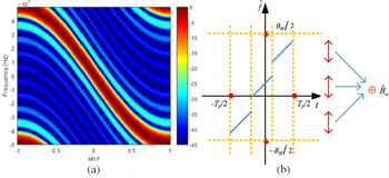
Although the range-angle dependent beampattern is the most important feature of a standard FDA system, the range-angle coupled echo is difficult to process. Therefore, some researchers, such as [Reference Liao, Wang and Zheng12–Reference Li and Shi21], focus on the waveform design method to achieve a range-angle decoupled beampattern and focus signal power at a desired area. Usually, a range-angle decoupled beampattern is dot-shaped. Although the dot-shaped transmit beampattern can enhance the signal energy in the target area, the dot-shaped beam cannot automatically scan space without the aid of phase shifters or a rotating array. Wang et al. [Reference Wang, Liao Zhu and Xu22, Reference Wang, Liao, Xu and Zhu23] have proposed a waveform design method based on piecewise linear frequency modulation (LFM) signals and dividing space into Q continuous angular sectors, to achieve automatic beam scanning and increase the echo signal energy. Since distinct sub-LFM signals are distributed in different angular sectors, the transmitted beampattern, as shown in Fig. 1, is angle-frequency dependent. The ambiguity function presented in [Reference Wang, Liao, Xu and Zhu23] shows that the piecewise LFM–FDA system has a good target detection performance. However, in the piecewise LFM–FDA system, the transmitted waveform of each element contains multiple sub-LFM signals. For example, Fig. 1(b) shows the time–frequency distribution of a certain element's transmitted signal in one case. Due to the complex transmission signal, the piecewise LFM–FDA system has high hardware requirements for the transmitters.
(a) Transmit beampattern of the angle-frequency dimension reported in [Reference Wang, Liao, Xu and Zhu23]. (b) Time–frequency distribution diagram presented in [Reference Wang, Liao, Xu and Zhu23].

In this paper, we are intended to design simple waveforms for an FDA system, to achieve automatic beam scanning and enhance echo signal energy. Therefore, we propose a waveform design method based on diversity LFM waveforms for the FDA radar system (the diversity LFM–FDA system). In the proposed method, the chirp rates of different elements are various, which are optimized by the artificial bee colony (ABC) algorithm to reduce sidelobe levels while increasing pulse duration. The ABC algorithm is a global optimization algorithm proposed by Karaboga [Reference Karaboga and Basturk24] and can efficiently be used for multivariable, multimodal function optimization. Thereby, we adopted the ABC algorithm in this paper. Correspondingly, we propose a receiver architecture with time-variant beamforming chain to achieve target detection. Compared with a conventional orthogonal frequency division multiplexing LFM (OFDM–LFM) radar system [Reference Cheng, He, Liu and Li25, Reference Chen, Liu and Zhang26], the proposed system has a higher spectrum utilization.
The rest of this paper is organized as follows. Section “The proposed waveform design method” reports the proposed waveform design method and the corresponding receiver architecture. Section “Numerical simulation” reports and discusses a set of simulation examples. Finally, conclusions are drawn in “Conclusion” Section.
The proposed waveform design method
Fundamental of the proposed system
Let us consider a monostatic radar with a linear array system. The linear array consists of N elements with the first element as the reference element. The inter-element spacing is d = λ 0/2, where λ 0 is the carrier wavelength of the reference element. The array structure is shown in Fig. 2.
Array structure of the monostatic radar system.

The transmitted signal of each element is designed as:

where f 0 is the carrier frequency of the reference element and f n denotes the carrier frequency of the nth element. n × Δf denotes the frequency offset of the nth element and T is the pulse duration. The frequency offset satisfies Δf ≪ f 0. Hence, the FDA system is a narrowband system. As mentioned before, when the pulse duration satisfies T ≥ [2(f 0 − Δf)d]/(cΔf), the standard FDA can automatically scan the space. And under the premise of a narrowband system, the pulse duration can be designed as T ≥ 1/Δf approximately.
The baseband waveforms are designed as

where u n denotes the chirp rate of the nth element and B n denotes the bandwidth of the nth baseband waveform.
Suppose there is a target at point (r, θ) with the radial velocity v. Then, the accurate received signal model of the mth element can be derived as:

where $t\in ( {{-T} / 2} + \tau _{m, n}, \;{T / 2} + \tau _{m, n}) , \;$ τ m,n denotes the delay of each echo signal relative to the transmitted signal, c denotes the speed of light in free space, and ${\bf n}( t)$
 represents the received additive white Gaussian noise with a mean of 0 and a variance of $\delta _n^2$
 .
Gui et al. [Reference Gui, Wang, Cui and So27, Reference Gui, Wang and Shao28] proposed general receiver structures for an FDA radar based on the maximum likelihood criterion. In these general receiver structures, each antenna channel consists of multiple demodulators with different carriers and several matched filters. Based on these structures, we introduce a time-varying beamforming chain in each antenna channel. And the proposed receiver architecture is shown in Fig. 3.
Single-antenna receiver architecture with a time-varying beamforming chain.

In the proposed system, each receiving channel consists of an analog mixer, an analog-to-digital converter (ADC), N digital mixers, and N approximate matched filters. And the sampling rate of the ADC is f s. In actual processing, the ideal matching filtering is impossible to achieve and the impulse compression performance is related to the time-bandwidth (TB) product of the signal. Kowatsch et al. [Reference Kowatsch, Stocker, Seifert and Lafferl29] studied the performance of an LFM pulse compression system for TB products between 10 and 400. In practical application, we can choose the appropriate TB product to meet the specific needs.
Then, the impulse response function of the m–nth matched filter is h m,n(k) = exp [ − jπu n(K − 1 − k)2], where k denotes the discrete time point and K denotes the total number of discrete points. Each channel can capture all the transmitted signals respectively, thanks to different chirp rates. The output signals of N beamformers are accumulated as y m(k). Then, the output signals of the N receiving channels are accumulated as $y( k) = \sum\nolimits_{m = 0}^{N-1} {y_m( k) }$ .
With the premise of a narrowband system (f 0 ≫ (N × Δf), f 0 ≫ max (B n)), the equivalent output signal model of the ADC can be approximately derived as:

where τ 0 = 2r/crepresents the reference time delay, and f d = 2f 0v/c denotes the Doppler frequency. Then, the output signal of the m–nth digital mixer can be derived as:

Then, the envelope of the output signal of the m–nth matched filter can be derived as:

where * denotes convolution operation. To effectively accumulate the filtered outputs, the complex weighting factor is designed as ω m,n(k′) = exp (j2πnΔfk′ − jπf 0(n + m)sinθ), where k′ denotes the discrete time of the output of matched filter. Therefore, the weighting factor is time-varying. When a radar system is designed, the value of ω m,n(k′) at a certain moment is determined. Thereby, we can calculate and store ω m,n(k′) in advance, and then call the corresponding value when beamforming.
The proposed waveform design method
Based on the relationship between the TB product and the pulse compression performance reported in [Reference Kowatsch, Stocker, Seifert and Lafferl29], we can choose the appropriate TB value according to the needs of the actual application. Since the baseband waveforms are not mutually orthogonal, the second addend in (6) cannot be ignored. Then, the high side lobe level may occur. In order to reduce the impact of this addend, we apply the ABC algorithm to find the appropriate chirp rate u n of each element. And u n is designed as u n = Δf × η n/T, where η n is the weighting factor that needs to be optimized. The determination of the distribution value of η n can be considered as a minimization problem of the cost function Ψ given by (7), where SLLmax represents a function that can find the highest sidelobe level. And the SLLmax function can be implemented by finding the global submaximal value. The $s_{m, n}^{\rm \prime\prime } ( k )$ is derived with the assumption that there is a stationary target at point (r′′, θ′′) and $\tau _0^{\rm \prime\prime } = 2r{\rm \prime\prime }/c$
 . H denotes the Heaviside step function, and SLLd represents the desired sidelobe level:

Inspired by Yao et al. [Reference Yao, Wu and Fang30, Reference Yao, Rocca, Wu, Massa and Fang31], the optimization process based on the ABC algorithm is shown in Table 1.
Optimization process of ABC algorithm

The ABC algorithm is a global optimization algorithm based on the intelligent foraging behavior of honey bee swarm. Besides, it can be efficiently used for multivariable, multimodal function optimization. In the ABC model, the colony consists of three groups of bees: employed bees, onlookers, and scouts. It is assumed that there is only one artificial employed bee for each food source. Employed bees go to their food source and come back to hive and dance on this area. The employed bee whose food source has been abandoned becomes a scout and starts to search for finding a new food source. Onlookers watch the dances of employed bees and choose food sources depending on dances. Then the honey bee swarm can accomplish tasks through social cooperation. The first half of the swarm consists of employed bees, and the second half constitutes the onlooker bees. Therefore, the optimization starts from randomly distributed initial values x i,n (i = 1, 2, …, SN/2, n = 0, 1, …, N − 1, where SN is the size of the bee colony). And updates x i,n at the qth iteration (q = 1, 2, …, Q, where Q is the preset maximum number of iterations). The greedy selection criterion is as follows. First, we compare the probability value of the old solution x i,n and the new solution v i,n based on (8). Then, replace x i,n by v i,n for the next iteration and update η n = v i,n as a possible solution, if p(v i,n) > p(η i,n); otherwise, retain x i,n and update $\eta _n{\rm} = x_{i, n}$ .
The probability value p i is evaluated using (8), where fit(x i,n) is the fitness function value of Ψ(x i,n):

Numerical simulation
The parameters of the FDA radar system are set as follows: N = 10, f 0 = 10 GHz, Δf = 100 kHz, and f s = 8 MHz. To increase the average echo signal energy, we set the pulse duration as T = 4/Δf = 40 μs. In the beamforming process, the number of discrete points of angle dimension is 181. The parameters of the ABC algorithm are set as follows: SN = 20 and Q = 200. The desired normalized sidelobe level is set as −12 dB. Refer to the performance of the LFM pulse compression system reported in [Reference Kowatsch, Stocker, Seifert and Lafferl29], we let B n × T > 30 to compress the echo signal with approximate matched filters. Considering that the pulse width is T = 4/Δf, the bandwidth of each waveform should satisfy B n > 7.5Δf. Therefore, we set η min = 7.5 and η max = 30.
After doing the Monte Carlo experiment, we draw the curve of fitness function values with the number of iterations as shown in Fig. 4. In addition, the average time of 100 simulation experiments is 17.9228 s, which is obtained on a desktop equipped with 4 cores at 1.6 GHz and 8 GB RAM. The results of Monte Carlo experiment show that the algorithm has convergence. And the optimized B n of one simulation experiment are shown in Table 2.
Curve of fitness function value with the number of iterations.

Optimized bandwidth (B n = Δf × η n) of each chirp signals

For convenience, the bandwidth of each signal is accurate to 1 kHz. For example, B 0 is designed as 1539 kHz. Then, the frequency ranges of each element are shown in Fig. 5. And the total bandwidth of the radar system is about 2.865 MHz. Hence, the radar system is a narrowband system and the approximation process in (4) holds. Besides, the sampling rate of the ADC satisfies the Nyquist–Shannon sampling theorem. In the conventional OFDM–LFM radar system, the spectrum of each signal is not overlapping. Therefore, the proposed system has a higher spectrum utilization.
Range of frequency variation of each array element.

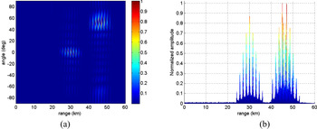
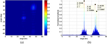
Then, suppose there are three targets: (30 km, 0°, 100 m/s), (47 km, 52°, 50 m/s), and (45 km, 50°, 50 m/s) and assume that the signal to noise ratio (SNR) of the echo signal is 0 dB. The target detection results of the standard FDA system, by contrast, are shown in Fig. 6. The target detecting results of the proposed diversity LFM–FDA radar system with time-variant beamforming are shown in Fig. 7. Except for the baseband waveforms, the remaining parameters of the standard FDA system are the same as those in the proposed system. Compared with the standard FDA system, the proposed system not only detects these three targets effectively but also reduces the sidelobe peaks of the range dimension of the detection results.
Detecting results of the standard FDA radar system: (a) range-angle map and (b) range dimension projection.

Detecting results of the proposed diversity LFM–FDA radar system: (a) range-angle map and (b) range dimension projection.

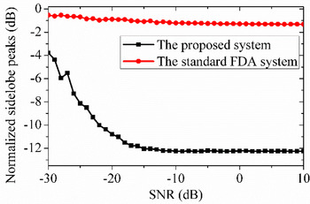
To compare the performance of the proposed diversity LFM–FDA system with the standard FDA system under different SNR conditions, we assume there is a target at (30 km, 0°, 100 m/s) and let SNR range from −30 to 10 dB. The simulation results are shown in Fig. 8. When SNR ≥ −15 dB, the proposed system achieves sidelobe peaks 11 dB lower than the standard FDA system. Although the sidelobe peak is increasing as SNR decreases, the side lobe of the proposed system is still lower than that of the standard FDA system. Hence, the proposed system can increase the echo signal energy by increasing the pulse duration and keep the sidelobe peaks at a low level.
Normalized sidelobe peaks vary with the SNRs.

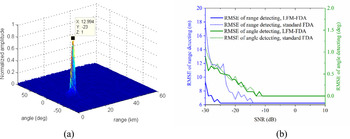
In addition, to analyze the applicability of the proposed waveform design scheme, we changed the carrier frequency to 3 GHz, SNR = −10 dB, and changed target parameters to (13 km, −23°, 0 m/s). The rest of the parameters remained unchanged. The target detecting result is shown in Fig. 9(a). When the SNR is changed from −30 to 10 dB, the root mean square error of the angle detecting and the range detecting for target (13 km, −23°, 0 m/s) are shown in Fig. 9(b). Simulation results show that the proposed scheme can be applied to 10 and 3 GHz. The angle detection performance of the proposed scheme is close to the standard FDA system, and the range detection performance is better than that of the standard FDA system. Considering that the proposed scheme can provide lower side lobes, the proposed scheme has a better application prospect.
(a) Target detecting result at f 0 = 3 GHz, SNR = −10 dB and (b) target detection performance comparison between the proposed system and standard FDA system.

The simulation results show the effective ranging performance of the proposed system. Since it is a narrowband system, the conventional DOA estimation algorithm, such as the ESPRIT algorithm, can be applied to achieve high resolution angle estimation of the target. Besides, because the covariance matrix of the transmitted waveforms is full rank, the proposed system can be combined with MIMO radars to achieve super-resolution parameter estimation.
Conclusion
FDA systems are more suitable for target search and detection than conventional phased array systems, thanks to the feature of automatically beam scan. However, if we increase the pulse width in a standard FDA radar to increase echo signal energy, the high side lobe level problem will occur. To overcome this problem, we proposed a diversity LFM–FDA system. In the proposed scheme, we apply the ABC algorithm to optimize the bandwidth of each waveform. Then, multiple approximate matched filters are applied in each receiver channel to compress transmit signals respectively. Finally, we use time-variant beamforming to combine the output signals of matched filters. The presented simulation results show that the proposed system effectively reduces the side lobes of the range dimension while increasing the pulse width. In this paper, the optimization is not performed in real-time. Some other algorithms, such as genetic algorithm and ant algorithm, are also applicable to this system. In practical applications, the operation speed of the beamforming module may be the difficulty of the system implementation. In future research, we will improve the algorithm to reduce hardware requirements. Besides, we are dedicated to studying anti-interference beamforming and side lobe suppression methods when increasing the pulse duration.
Acknowledgement
This study was supported in part by the National Natural Science Foundation of China under Grant 61271331 and in part by the National Natural Science Foundation of China under Grant 61571229.
 Zhonghan Wang was born in Nantong, China, in 1993. He received his B.E. degree in telecommunication engineering from Xidian University in 2016. He has enrolled in the Nanjing University of Science and Technology, Nanjing, Jiangsu Province, China as a Ph.D. student. His main research interests are beamforming, radar signal processing, radar imaging, and wireless communication.
 Yaoliang Song was born in Wuxi, China, on June 30, 1960. He received his B.Eng, M.Eng., and Ph.D. degrees in electrical engineering from the Nanjing University of Science and Technology, China, in 1983, 1986, and 2000, respectively. From September 2004 to September 2005, he was a Researcher Fellow with the Department of Engineering Science at the University of Oxford. He is currently a Professor at the Nanjing University of Science and Technology, and is heading the UWB Radar Imaging Group. His research interests include UWB communication, UWB radar imaging, and advanced signal processing.