I. INTRODUCTION
In recent years, exploration in particulate reinforced aluminium matrix composites (AMCs) has been carried out by many researchers due to their superior specific properties. Reference Prashanth, Scudino, Chaubey, Lober, Wang, Attar, Schimansky, Pyczak and Eckert1–Reference El Mahallawi, Shash, Rashad, Abdelaziz, Mayer and Schwedt5 Reinforcements in the form of particles are deliberated because they exhibit isotropic material properties and good formability. Reference Sulima, Klimczyk and Malczewski6,Reference Ram Prabhu, Varma and Vedantam7
Aluminium based composites operated under high temperature will subject to oxide wear. Inclusion of suitable oxide reinforcement will form a protective layer which constrains direct contact of metals thereby reducing material loss. Aluminium is potentially reinforced with hard and soft materials like SiC, Al2O3, TiC, TiB2, graphite, mica, etc. Reference Walczak, Peiniak and Zwierzchowski8,Reference Garbiec, Jurczyk, Levintant-Zayonts and Moscicki9 Preceding outcomes of various researchers explored that hard reinforcements show good wear, corrosion, and seizure resistance at high sliding velocity but at the expense of poor machinability whereas soft reinforcements with low friction characteristics improves machinability. Hence, aluminium is hybridized with both hard and soft phases to accomplish enhanced mechanical and wear properties along with improved machinability. Reference Arun Premnath, Alwarsamy, Rajmohan and Prabhu10–Reference Rajmohan, Palanikumar and Ranganathan12 However, availability, cost, and environmental facets limit the applications of the above as reported by Bodunrin et al. Reference Bodunrin, Alaneme and Chown13 Identification of an appropriate strengthening material which clenches good mechanical, wear, & machinability properties, readily available and environment supportive is therefore essential.
Rutile, a natural mineral, rich in TiO2, is extravagantly available, economical, and environment receptive material. Rutile (TiO2) has excellent mechanical properties, wear, and corrosion resistance. Reference Siva Rama Krishna, Brama and Sun14–Reference Mohapatra, Kumar Mishra, Mishra, Roy, Behera, Mantry and Singh17 Rutile (TiO2) is also a potentially low friction material due to the presence of thermally stable TiO2. Reference Sun18 Considering all the above aspects, rutile can be a good alternate to conventional TiO2. A.A. Hamid et al. Reference Hamid, Ghosh, Jain and Ray19 stated that inclusion of an oxide phase to aluminium substantially enhances its mechanical and tribological properties. Y. Zhu et al. Reference Zhu, Zhou, Ji, Jia, Wang, Wu and Zan20 perceived that the TiO2 film formed on the worn surface of Ti3SiC2 decreases coefficient of friction as well as wear rate. These superior tribological properties of rutile (TiO2) make it desirable for a broad spectrum of applications via, automotive, aerospace, structural fields, etc.
Critical reviews of various literature studies reveal that no extensive evaluation was made on wear behavior of Al–rutile (TiO2) composites using powder metallurgy (P/M). S.K Chaudhury et al. Reference Chaudhury, Singh, Sivaramakrishnan and Panigrahi30 and Rama Arora et al. Reference Arora, Kumar, Singh and Pandey34 have made a prospective study by Al–rutile composites which justifies the feasibility of using rutile as a reinforcement. However, both literature studies processed their material using the liquid metallurgy technique. Powder metallurgy facilitates us to attain uniformity in composition and better interface between the matrix and the reinforcements. Reference Sundararajan and Selwin Rajadurai21–Reference Zou, Zou, Yang, Qu and Li23 Hence the present work made a novel attempt by using powder metallurgy to process the material. The present investigation therefore added rutile (TiO2) to Al using the P/M route to examine its influence on dry sliding wear behavior and microhardness property of Al matrix. Worn surface was characterized using scanning electron microscope (SEM) and energy-dispersive x-ray spectrometer (EDS) to discover the mechanism of wear. Wear debris studied using SEM images as well specify the mechanism of wear.
II. EXPERIMENTATION
A. Preform preparation
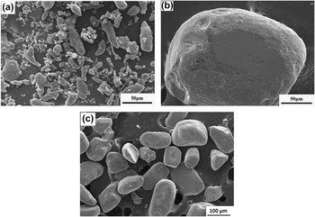
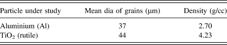
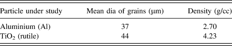
The investigation was carried out with pure atomized aluminium and TiO2 (rutile) holding an average particle sizes of 37 and 44 μm, respectively. ASTM B-214 was followed in the selection of average particle size of aluminium. Al particle was procured from M/s Metal powder corporation, Sivakasi, Tamilnadu, India and rutile powder was acquired from Kerala Minerals and Metals Ltd., Kerala, India. Particle size and morphology of as-received powders was revealed through respective SEM micrographs [Figs. 1(a)–1(c)]. Table I delivers the physical attributes of the particles under study.
Particle morphology of as-received: (a) aluminium powders, (b) TiO2 (rutile) particles in low scale, (c) TiO2 (rutile) particles in high scale.

Physical attribute of particles under study.
Al composites were synthesized with TiO2 (rutile) particles in different proportions (0, 4%, 8%, 12%, mass fraction) using the powder metallurgy route. Powders were weighed to an accuracy of 0.001 g using an electronic weighing machine. Powders were then mixed uniformly using a planetary mixer accompanied by 12 mm diameter steel balls which ensured riddance of particle agglomeration. Powder blend was preheated to 200 °C to achieve effective bonding of reinforcement to the matrix. Preheated particle mixture was cold compacted at 800 MPa in a uniaxial press. The green compacts were sintered to 650 °C in an electric muffle furnace for 2 h and subsequent cooling inside the furnace for 8 h. Reference Yusuf24 The composite specimens were turned to 12 mm diameter and 30 mm height to suit testing standards.
B. Physical attributes
The volume fraction of the reinforcements is obtained as follows, Reference Ajith Kumar, Viswanath, Rajan, Pillai and Pai25
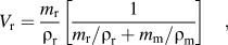 $${V_{\rm{r}}} = {{{m_{\rm{r}}}} \over {{\rho _{\rm{r}}}}}\left[ {{1 \over {{{{m_{\rm{r}}}} \mathord{\left/ {\vphantom {{{m_{\rm{r}}}} {{\rho _{\rm{r}}}}}} \right. \kern-\nulldelimiterspace} {{\rho _{\rm{r}}}}} + {{{m_{\rm{m}}}} \mathord{\left/ {\vphantom {{{m_{\rm{m}}}} {{\rho _{\rm{m}}}}}} \right. \kern-\nulldelimiterspace} {{\rho _{\rm{m}}}}}}}} \right]\quad ,$$
where V r-volume fraction of TiO2 (rutile), m r-mass fraction of TiO2 (rutile), m m-mass fraction of Al matrix, ρr = 4.23 g/cm3, density of TiO2 (rutile), ρm = 2.7 g/cm3, (density of Al).
The theoretical density of Al–TiO2 (rutile) composites was calculated using the rule of mixtures, which is expressed as,
 $${\rho _{{\rm{th}}}} = {\rho _{\rm{m}}}{V_{\rm{m}}} + {\rho _{\rm{r}}}{V_{\rm{r}}}\quad .$$
Archimedes' principle was used to figure out sintered density (ρs) which involves weighing preforms in air and after immersion in distilled water. Sintered density was calculated according to
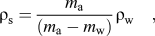 $${\rho _{\rm{s}}} = {{{m_{\rm{a}}}} \over {\left( {{m_{\rm{a}}} - {m_{\rm{w}}}} \right)}}{\rho _{\rm{w}}}\quad ,$$
where ρs-sintered density (g/cm3), ρw-density of water (g/cm3), m a-mass of preform in air (g), m w-mass of preform in water (g).
Composite samples were weighed using a balance of accuracy 0.001 g. Sintered density was then compared with the theoretical density and the values are correlated using the following relation to obtain porosity (P) and the relative density (ρR) of the composites. Reference Yin, Zeng, Yao, Xia and Zuo26
 $$P = 1 - {{{\rho _{\rm{s}}}} \over {{\rho _{{\rm{th}}}}}}$$
 $${\rm{Relative\ density}}\left( {{\rho _{\rm{R}}}} \right) = 1 - P$$
C. Examination of microstructure
The microstructure of the preforms was examined using optical microscope (Make: QS Metrology, Mumbai, India and Model: JSJL 17). The quality of reinforcement distribution within the matrix and the nature of the grains can be revealed through microstructural study.
Standard procedure was adopted to prepare samples for microstructural investigation. Silicon carbide (SiC) abrasive papers of grades 400, 1000, 1400, and 2200 were utilized to polish the surfaces under observation. Diamond paste was then applied on the surface followed by suspension in distilled water to attain fine polishing. Grain size was realized after the preforms were subjected to etching using Keller's reagent and allowed to settle for 10 s. Microstructural observations of all samples were made with same magnification to enable comparative study.
D. Microhardness and wear tests
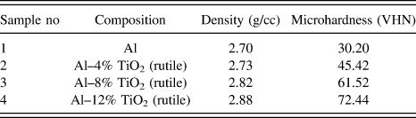
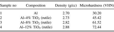
A microhardness test was carried on the polished samples in accordance with ASTM E384 11e1 using Vicker's hardness testing machine (Make: Mitutoyo, Japan). Before subjecting to hardness test, the composite preforms were polished in two stages by standard procedure. Rough polishing was carried out using SiC abrasive paper followed by fine polishing with 1 μm diamond paste. The prepared surfaces were subjected to 10 N load at a dwell time of 10 s. The measurements were undergone at twenty different regions on the preform surface and the mean was computed. Table II presents the mechanical properties of the proposed composites.
Mechanical properties of samples.
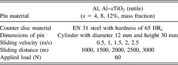
The dry sliding wear test was performed on the proposed composites using pin-on-disc apparatus (Make: Ducom, Bangalore) at 60 N load as per ASTM G99-05. The samples in the form of pin with 12 mm diameter and 30 mm length were turned out from the sintered preforms. Before the test, the contact surfaces of the pins and the counter disc were cleaned with acetone. The counter disc chosen was on EN 31 grade steel hardened to 65 HRc and ground to 1.6 R a surface roughness. The mass loss of the pin was measured using an electronic weighing instrument holding an accuracy of 0.001 g. Worn surfaces and wear debris of the proposed composite specimen were characterized using SEM micrographs. Table III shows the particulars of wear parameters and testing conditions adopted.
Details of wear factors used for study.

III. RESULTS AND DISCUSSION
A. Observation on density
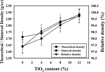
The disparity in theoretical, sintered, and relative densities with the mass fraction of TiO2 is presented in Fig. 2. The analysis reveals that with the increase in the proportion of TiO2 all types of densities under observation show raising curves. Furthermore, the proposed composites display better density values than the base Al matrix. Enhanced density of Al–TiO2 composites than that of the base matrix is due to the high density of TiO2 which enables uniform dispersal of density throughout the sinter. Reference Whon Lee, Morillo, Lira-Olivares, Kim, Sekino, Niihara and Hockey27 Homogeneity in density forecasts improved microhardness property throughout the composite surface. The graphical results also exhibit a proportionate reduction in the porosity of preforms with an addition in the fraction of TiO2. The mechanical properties of the composites can be enhanced since minimum pores in preforms designate less stress concentration regions.
Variation of theoretical and sintered density with mass fraction of TiO2.

B. Observation on microhardness
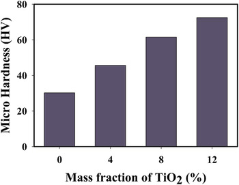
Figure 3 expresses the variation in microhardness of the samples with respect to the quantity of TiO2. The study infers that hardness increases linearly with the mass fraction of TiO2. The homogeneous dispersion of reinforcements within the matrix readily influences the linearity of hardness value with regard to the mass fraction of the Al matrix which is brought out by the optical microscopy images (refer Fig. 4). Reference Arora, Kumar, Singh and Pandey34 Al–12% TiO2 composite reveals high hardness when compared with other compositions. Improved hardness will lead to high wear resistance. Sintering samples at high temperature results in grain growth, which readily influences the mechanical properties of the composites. Reference Baghchesara and Abdizadeh28 Raising the fractional amount of TiO2 in Al matrix restraints the dislocation motion of the slip plane during sliding and prevents the grain growth. Therefore the dislocation density is high which enriches microhardness value of the proposed composites. High hardness of Al–TiO2 composite is also due to the possession of better hardness by TiO2 than the base matrix.
Microhardness of Al matrix, Al–4% TiO2, Al–8% TiO2, and Al–12% TiO2 composites.

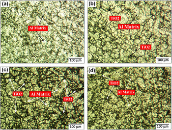
Microstructure of (a) Al matrix, (b) Al–4% TiO2, (c) Al–8% TiO2, and (d) Al–12% TiO2 composites.

C. Interpretation of microstructure
The homogeneity of TiO2 distribution within Al matrix is depicted in Figs. 4(a)–4(d). Uniform dispersion of reinforcements in the matrix is essential to accomplish isotropic properties in the composites. Optical microscopy images of all composites confirm the uniform distribution of TiO2 within the Al matrix. Grain boundaries are prominent from the micrograph which specifies good interface bonding between the reinforcement and the matrix. Effective integrity of the Al–TiO2 particle interface facilitates TiO2 particles to acquire constant distribution of load from the matrix. Minimum pores are also witnessed from the OM images when the mass fraction of TiO2 approaches high scale.
D. Friction characteristics study
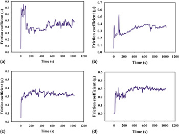
Figures 5(a)–5(d) represents the variation in friction coefficient of the projected composites pertaining to time. The results indicate that for all compositions, friction coefficient exhibits steep rise in magnitude during the run-in period and fluctuates about the mean during further sliding. The instability of friction coefficient about the mean is more for Al matrix and with increasing content of TiO2 the instability is less. The friction curve is getting smoother when the mass fraction of TiO2 is high. Reference Soltani and Hoseininejad29 Preform reinforced with 12% TiO2 attains a steady state in a shorter period of time than the other compositions. Smooth curve depicts the effectiveness of reinforcing a low friction and thermally stable TiO2 particles.
Friction coefficient versus time for (a) Al matrix, (b) Al–4% TiO2, (c) Al–8% TiO2, and (d) Al–12% TiO2 composites.

On the repetition of surface interactions and surface and subsurface stresses, developed at the interface, failure of the mating surfaces takes place which results in the formation of wear particles. During the run-in period for Al matrix high asperites are knocked off, which is reflected as high coefficient of friction. Hence the failure of Al matrix surface initiates within 100 s. During the steady state period, the wear particles got trapped between the mating surfaces and led to progressive wear of Al matrix. In case of the composites, the transition to a steady state from the run-in period took place just after 100 s and the curve shows low friction coefficient indicating minimum wear.
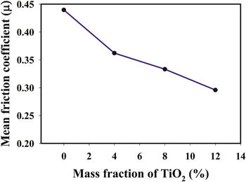
The disparity of mean friction coefficient with TiO2 content an applied load of 60 N, sliding velocity of 2.5 m/s, and sliding distance of 3000 m is presented in Fig. 6. The graphical analysis reveals that the friction coefficient drops linearly with TiO2 quantity. Reference Chaudhury, Singh, Sivaramakrishnan and Panigrahi30 High content of TiO2 (12%) portrays relatively lower friction coefficient than other projected composites. The presence of more oxide phases leads to the development of low shear strength film during sliding which reduces the effective contact area of surfaces and brings down the friction force. The lower friction coefficient is also ascribed to softening of the hard faces during plastic deformation which led to drop in plowing component of friction.
Disparity of mean friction coefficient with the quantity of TiO2.

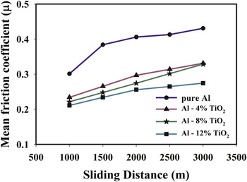
The impact of sliding distance on the friction characteristics of the proposed composites is presented in Fig. 7. Variation in friction coefficient reflects the friction characteristics of the composites. Graphical analysis infers that friction coefficient increases along with the sliding distance. Nevertheless, for a specific sliding distance it decreases with increase in percentage of TiO2. Composites reinforced with 12% TiO2 exhibit a lower friction coefficient than the other proportions of materials. High sliding distance refers to more period of contact between the sliding surfaces which support ejection of wear particles. During sliding, wear particles entrapped between the sliding faces and at high sliding distance trapped particles raise the frictional force and its corresponding coefficient. The shearing-off of oxide phases owing to more duration of contact exposes the true contact surfaces and with further sliding enables the friction force to reach high magnitude.
Impact of sliding distance on the friction coefficient of the proposed composites.

E. Wear analysis
1. Effect of TiO2 (rutile)
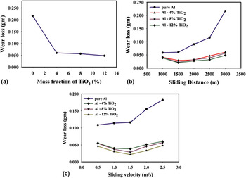
Graphical representation of the impact of TiO2 quantity on the wear loss of Al–TiO2 composites at an applied load of 60 N, sliding velocity of 2.5 m/s, and a sliding distance of 3000 m is offered in Fig. 8(a). It is observed that addition of TiO2 to Al matrix reduces the wear loss of the composites. Wear loss decreases with the increase in the measure of TiO2. Reference Ghazali, Forghani, Hassanuddin, Muchtar and Daud31 Al–12% TiO2 exhibits better resistance to wear than the rest of the composites. High hardness of TiO2 influences the wear behavior of the materials and thus supports low loss of material. Increasing the mass fraction of TiO2 improves the strain hardening rate, which is the outcome of uniform distribution and good interfacial bonding of the particles with the matrix. High hardness, effective strain hardening, respectable interfacial bonding increases bulk shear strength of the material and restricts the plastic flow during sliding which ends in low wear loss.
Wear analysis of Al–xTiO2 (x = 0, 4, 8, 12%) with respect to (a) mass fraction of TiO2, (b) sliding distance, (c) sliding velocity.

2. Effect of sliding distance
Figure 8(b) displays the change in wear loss of the proposed composites with respect to sliding distance. The wear loss curve of the Al matrix shows an increasing trend along with sliding distance, whereas for Al–TiO2 composites the wear loss drops up to a sliding distance of 1500 m and elevates beyond that. However, at a specific sliding distance the material removal decreases when the percentage of TiO2 reaches high scale. Reference Ramesh, Anwar Khan, Ravikumar and Savanprabhu32 When the sliding distance stands below 1500 m the high points of the composite surface interacts with the mating surface and forms loose fragments. These fragments, on further sliding got trampled to form a protective layer which reduces the effective area of contact and reduces loss of material. Hence the Al–TiO2 composites underwent low material loss below 1500 m. At high sliding distance when the shear force at the interface exceeds the breaking strength of the material, the protective layer gives way to expose the true surface of contact and encourages more wear loss of material.
3. Effect of sliding velocity
Sliding velocity represents the rate of contact between the sliding faces. The influence of sliding velocity on the deprivation of the material is shown in Fig. 8(c). The change in wear loss of Al matrix responds proportionately to sliding velocity. The rise in slope of the wear loss curve of Al matrix is low up to 1.5 m/s which designates mild wear and beyond 1.5 m/s the variation is slope is considerably high which signifies severe wear. It is apparent from the analysis that Al–12% TiO2 unveils better wear resistance than other fractions of TiO2 reinforced composites at constant sliding velocity. The study also reveals that the wear loss of proposed composites reduces up to 1.5 m/s and increases subsequently. Increase in wear resistance below 1.5 m/s sliding velocity is due ostensibly to the increase in strain rate, which increases the yield stress of the material. But at high sliding velocities, the yield stress of the material being tested is reduced owing to high interface temperature as a result of frictional heating which offsets the effect of improved strain rate. Reference Selvi and Rajasekar33
4. Worn surface characterization
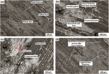
Figures 9(a)–9(d) portray the SEM micrographs of the worn surface of proposed composites. Figure 9(a) represents the worn surface of pure Al matrix. The image denotes a rough surface indicating severe wear. During sliding, at high sliding distance the material experiences severe plastic deformation which is reflected by plastic flow and deep grooves. During transverse motion, the high points of the surfaces make contact and penetrate the opposing surface. The interaction between the surface stimulates plastic deformation thereby increases the pressure and energy density within the deformed region. This contributes to elevated adhesion between the surfaces and galling build-up. Thus the worn surface of Al matrix experiences abrasion at the beginning and proceeds with delamination mechanism of wear.
SEM images characterizing worn surfaces of (a) Al matrix, (b) Al–4% TiO2, (c) Al–8% TiO2, and (d) Al–12% TiO2 composites at an applied load of 60 N, sliding velocity of 2.5 m/s and sliding distance of 3000 m.

Worn surface of Al–4% TiO2 reports noticeable grooves and particle pull out [Fig. 9(b)]. During sliding, the surface was subjected to plastic deformation and the particles are sheared off from the surface as fragments. On subsequent sliding, part of the sheared particles is fractured due to the compressive force applied by the counter face and the rest of particles tricked between the sliding faces. The trapped particles resemble third body abrasive and formed grooves which are evident from the micrograph. From the SEM micrograph, it is also apparent that, at an elevated sliding distance the oxide layer was shackled and the true contact surface was exposed which stimulates increased loss of material. So the worn surface characterization of Al–4% TiO2 composite divulges severe adhesion.
The worn surface of Al–8% TiO2 composite displays similar pattern of wear in its respective SEM image [Fig. 9(c)]. The presence of slim grooves depicts less plastic deformation of the slip planes. During transverse motion between the sliding faces, due to plastic shearing the particle came off the surface and got transferred to the counter face. On successive sliding, the relocated fragments move toward the original surface, flattened and form a protective layer. The protective layer reduces the true contact area and minimizes wear loss from the composite surface. The existence of oxide layer also can reduce the wear loss by preventing direct metal-to-metal contact. Reference Arora, Kumar, Singh and Pandey34 Hence 8% TiO2 reinforced composites lost materials by abrasion at the beginning of sliding and then by adhesion. However, material loss is more pronounced by adhesion than by abrasion.
Figure 9(d) shows the worn surface of 12% TiO2 reinforced AMC. Al–12% TiO2 offers high resistance to wear which is specified by the absence of grooves on the worn surface. Low wear loss of 12% TiO2 reinforced composite is characterized by high dislocation density of successive planes thereby restricts plastic deformation. SEM micrograph of Al–12% TiO2 also exhibits the presence of agglomerated fragments which is imputed to the plastic shearing in accordance with the propagation of shear cracks. When crammed between the two surfaces, the particles are intensely stressed. As the counter face slides on, only residual elastic stress prevails which, when outstrip the adhesive strength of asperities, particles are detached as loose fragments. These loose fragments resist direct contact of sliding faces that reduces the friction force offering high wear resistance.
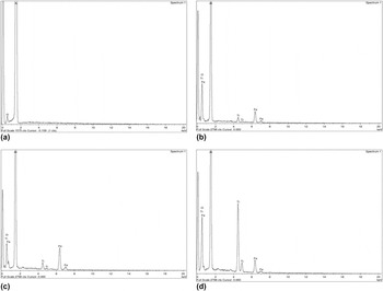
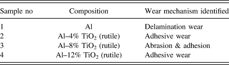
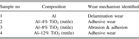
The EDS patterns of worn surfaces of the proposed composites are given in Figs. 10(a)–10(d). The pattern confirms the presence of oxide layer in all TiO2 reinforced composites. EDS patterns of Al composites reinforced with 12% TiO2 show minimum oxide phase when compared with that of the other fraction of TiO2 reinforced composites. Reference Arora, Kumar, Singh and Pandey34 High thermal stability of TiO2 (rutile) potentially restricts oxidation and has good bonding of particles with the matrix which is reflected by its high hardness. Table IV lists the wear mechanism of the projected proportions of composites.
EDS patterns of the worn surfaces of (a) Al matrix, (b) Al–4% TiO2, (c) Al–8% TiO2, and (d) Al–12% TiO2 composites at an applied load of 60 N, sliding velocity of 2.5 m/s and sliding distance of 3000 m.

Findings of worn surface characterization.
5. Characterization of wear debris
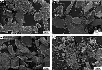
Wear debris was gathered during the tribological test, as the form and size of the debris dictate the mechanism of wear. Figures 11(a)−11(d) represents the wear debris of all proposed materials obtained during the dry sliding wear test. It is evident from Fig. 11(a) that the fragments from the worn surface of Al matrix resemble platelets. The platelets also show traces of plastic flow and cold welded particles which conclude the governance of delamination mechanism in material removal. The micrograph also portrays oxidized particles to indicate removal of oxide layer from the worn surface that promotes high material removal. The wear debris of 4% TiO2 [Fig. 11(b)] reinforced composites also possess platelet shape, but with restricted grooves. The presence of oxidized wear particles in the SEM image indicates the shearing of the protective oxide layer that stimulate high wear loss. Figure 11(c) characterizes the wear debris of 8% TiO2 reinforced composites. The SEM image confirms that the protective oxide layer was retained at high sliding distance as the image displays few oxidized particles among the debris. Consequently, worn surface of 8% TiO2 reinforced composites disclose the adhesive mechanism to remove materials. High content of TiO2 (12%) reduces the mean size of wear debris which is witnessed from Fig. 11(d). The SEM micrograph shows loose fragments among the debris supporting adhesive wear mechanism. Loose fragments restrict direct interaction of sliding faces and thereby minimizes loss of material.
SEM images characterizing wear debris of (a) Al matrix, (b) Al–4% TiO2, (c) Al–8% TiO2, and (d) Al–12% TiO2 composites at an applied load of 60 N, sliding velocity of 2.5 m/s, and sliding distance of 3000 m.

The presence of intermetallic phases in the wear debris of projected materials can be studied through EDS patterns Figs. 12(a)–12(d). EDS pattern of Al matrix approves the presence of more oxides. The presence of oxide phases in EDS pattern divulges flaking off of oxide layer from the worn surface of Al matrix. Preforms reinforced with 4% TiO2 and 8% TiO2 also have high oxide peaks in their respective EDS patterns. But the EDS pattern of 12% TiO2 reinforced composites show the minimum count of oxide phase when compared with the rest of the compositions. Minimum oxide phase infers that high content of TiO2 is not prone to oxidation due to its high thermal stability. High mass fraction of TiO2 also improves the shear strength of materials owing to its high hardness and offers high resistance to wear.
EDS patterns of wear debris of (a) Al matrix, (b) Al–4% TiO2, (c) Al–8% TiO2, and (d) Al–12% TiO2 composites at an applied load of 60 N, sliding velocity of 2.5 m/s, and sliding distance of 3000 m.

IV. CONCLUSIONS
Al matrix was reinforced with TiO2 (rutile), a natural material, in different proportions (0, 4%, 8%, 12%, mass fraction) through powder metallurgy route. Physical attributes viz., density and microhardness are observed to be increased with the fraction of TiO2. Raising the content of TiO2 also lowers the porosity values of proposed composites which reflect improved microhardness. Optical micrograph of the preforms infers uniform diffusion of TiO2 within the Al matrix thereby isotropic properties can be attained.
The wear analysis made on Al–TiO2 composites discloses that with the inclusion of TiO2 the composites deliver better resistance to wear than the unreinforced Al matrix. The composites reinforced with 12% TiO2 show improved wear characteristics. The mechanism of wear was well-known from SEM characterization of the proposed composites. From SEM micrographs it was inferred that delamination and adhesion were shown dominance in the removal of material during the sliding process.
SEM characterization of wear debris also facilitates us to identify wear mechanism. Delamination mechanism was confirmed through platelet shaped debris whereas adhesion is revealed through block shaped debris. Preforms reinforced with 12% TiO2 possess debris with reduced mean size.
EDS patterns of both worn surface and wear debris of the projected materials are certain in the presence of oxide phases in all compositions. Minimum oxide phases of 12% TiO2 designate good thermal stability of TiO2 (rutile). It is therefore evident from the findings of the tribological characterization of the proposed material, TiO2 (rutile) can be a potential means of enhancing the wear properties of Al composites. TiO2 (rutile) on account of its improved tribological properties and good thermal stability can place a novel initiative in the design of wear resistant and antifriction elements in a broad spectrum of applications.