1. Introduction
Parallel robots have many applications in the industrial field due to their high dynamics, high stiffness, and high load-bearing performance [Reference Zhao, Mei, Jin and Niu1–Reference Li, Li and Zhao3]. Compared with serial robots, the multi-link and multi-joint structure of parallel robots is relatively complex, and their motion space is smaller. As a result, while they have many advantages, they also have inevitable disadvantages and deficiencies [Reference Liu, He, Yang, Cao and Wu4–Reference Li, Wang, Chen, Wang, Sun, Zheng, Xu and Qin6]. Serial-parallel robots combine the features of both. This structure has a larger working space, higher flexibility, and more degrees of freedom of motion [Reference Guo, Cheng, Wang and Li7–Reference Xu, Yang, Xu, Yao, Zhou and Zhao9]. Therefore, a 5-DOF serial-parallel robot is proposed for mirror grinding. As the core component of the structure, the parallel module has four branches and a large number of motion joints and error sources, and there is a complex non-linear coupling relationship among various geometric error sources, which makes it extremely challenging to improve the motion accuracy of this type of robot.
Kinematics calibration is an economical and effective method to improve the motion accuracy of mechanisms [Reference Zhang, Shi, Chai and Ding10, Reference Wu, Kong, Li, Wang and Chen11]. Its core content is to construct a residual function between the theoretical and measured values of the end-effector pose. With the goal of minimizing the function value, parameter identification of geometric errors is carried out, and the input parameters in the model are iteratively updated to complete kinematics calibration.
Model-based kinematic calibration methods are typically classified into the error model method and the screw-axis measurement method. Among these, the error model method demonstrates higher calibration accuracy compared to the axis measurement method [Reference Santolaria, Conte and Ginés12]. The calibration process of the error model method mainly includes error modeling, parameter identification, and error compensation. Commonly used error-modeling methods include the screw method [Reference Guo, Wang, Hu, Zhang and Yang13], the D-H matrix method [Reference Yang, Lu and Xia14], and the vector differential method [Reference Feng, Yan, Jin and Chen15]. For example, Shen et al. employed the screw method to eliminate redundant error terms and developed a minimal motion error model for the serial-parallel robot [Reference Shen, Tang, Ye and Zhang16]. However, this method requires strict implementation of screw motion, and multiple error sources may be coupled together, making it difficult to separate the error sources. The D-H matrix method decomposes each branch chain into multiple independent joints and describes them using matrix transformations between adjacent joints, thereby constructing an error-mapping model by combining geometric error sources. Nevertheless, this method requires first defining a local coordinate system on a rigid body and then performing complex homogeneous coordinate transformations, which involve a large number of matrix differential operations, significantly increasing the complexity of modeling. In contrast, based on the first-order perturbation theory, the error-mapping model of the mechanism is formulated using the vector differential method. The error model constructed by this method is not only concise and intuitive but also has a clear physical meaning. For instance, Wang et al. selected a kind of 5-DOF dual-drive parallel mechanism as the research object and constructed its kinematic error model using the closed-loop vector differential method [Reference Wang, Sun, Wu, Cao, Guo and Liu17]. Error compensation is mainly achieved through two approaches: hardware compensation and software compensation. The method of hardware compensation is to comprehensively improve the performance from the processing of robot parts to the overall assembly. For example, high-precision encoders are used to improve the resolution of position feedback, and torque sensors are used to compensate for assembly errors. However, this method is costly and has poor flexibility. In contrast, the software compensation method achieves error compensation by correcting the control model through algorithms or modifying the input of the control system. This method is characterized by low cost and high operability. For instance, Drouet et al. constructed an endpoint error model for serial robots based on geometric parameters and compliance parameters. They identified these parameters through experimental measurement results and used the established model to achieve error correction during system operation [Reference Drouet, Dubowsky, Zeghloul and Mavroidis18].
By formulating a comprehensive error model and selecting an appropriate error compensation strategy, the accuracy of the end-effector pose can be significantly improved through parameter identification and kinematic calibration. Parameter identification is to identify the geometric errors of robots through measurement results. This method involves solving the residual extreme values between the actual and theoretical values of the input or output quantities. This process is usually regarded as a nonlinear least squares optimization problem. The nonlinear problem can be transformed into a linear problem by establishing a linear error model, and then the corresponding iterative algorithm can be used for the solution. As a critical component in kinematic calibration, the identification algorithm plays an essential role in enhancing the accuracy of robot parameter estimation [Reference Urrea and Pascal19]. As a result, researchers have proposed a variety of distinct identification methods. For example, the Levenberg–Marquardt algorithm [Reference Hoang and Wu20], which is a non-linear optimization algorithm. Its local convergence ability can effectively handle problems such as overparameterization or system singularity and exhibits strong robustness. However, when the search path is far from the optimal solution, the convergence efficiency of this algorithm will decrease significantly. The Extended Kalman Filter algorithm performs state estimation by performing a Taylor series expansion of the non-linear function near the optimal point [Reference Qi, Chen and Zhang21]. However, due to the influence of the error distribution, it may lead to filter divergence, thus reducing the accuracy of state estimation. The maximum likelihood algorithm estimates model parameters by constructing a likelihood function [Reference Ma, Bazzoli, Sammons, Landers and Bristow22], the convergence rate and estimation accuracy of which are critically determined by the singular values of the Jacobian matrix associated with the objective function. This algorithm necessitates a characterization of the noise distribution properties throughout the solution process. Furthermore, iterative optimization of nonlinear models may result in convergence at local optima, thereby compromising the global optimality of the solution. In addition, the least squares algorithm is also a widely employed method for parameter identification. As Luo et al. constructed an actual kinematic model with the minimal parameters based on the exponential function method, it identifies the orientation error and position error parameters separately by the iterative least-squares method [Reference Luo, Gao, Huang and Zhang23]. The least squares method is a commonly used identification algorithm in calibration research [Reference Huang, Ke, Zhang and Ota24]. This algorithm is simple to solve and suitable for efficient matrix operations. However, this algorithm is not without limitations. It not only requires a high degree of model linearization but also tends to produce biased fitting results when the observed pose errors exhibit significant fluctuations, thereby compromising the accuracy of actual kinematic parameter identification.
Considering the complexity of the structure of hybrid robots, when there are redundant variables in the error model or the identification matrix becomes singular due to the limitation of the measurement configuration, the robustness of the identification process will be directly weakened, resulting in a large deviation between the identification result and the true value. In order to mitigate the ill-conditioning problem encountered during the parameter identification process, for example, Liu proposed an identification algorithm based on singular value decomposition to deal with ill-conditioned identification matrices, aiming at the problem that the least squares method does not converge due to the different sensitivities of the identification matrix to different error terms. However, this algorithm needs to find the extreme values of relevant parameters through convergence analysis [Reference Liu, Wu, Wang and Wang25]. Some scholars, such as TANG et al., when using the iterative method to solve ill-conditioned matrices, adopted a pivoting weighted iterative algorithm to address the problems of slow convergence speed and low solution accuracy. By comparing with the Gauss-Seidel algorithm and the Jacobi iterative method, it can significantly improve the solution accuracy [Reference Tang and Li26].
In the constructed error model, parameter redundancy is commonly observed, and certain parameters to be identified demonstrate a degree of correlation. These factors tend to render the system of linear equations established to exhibit ill-conditioned properties, thereby significantly increasing the root mean square error of parameter estimation and ultimately compromising the accuracy of parameter identification. Therefore, effectively mitigating the ill-conditioning issue in the system of linear equations is of critical importance for improving calibration accuracy.
This paper aims to design an improved identification algorithm to improve the motion accuracy of the end-effector in serial-parallel robots by separating error sources and calibrating kinematic parameters. The rest of the paper is organized as follows: in Section 2, the topological structure and coordinate system of the serial-parallel robot are introduced. In Section 3, a kinematic model of the serial-parallel robot is constructed based on the closed-loop vector differential method. By separating the compensable error sources in the driving branches from the non-compensable error sources in the constraint branches, a kinematic error model is established. In Section 4, the identification error rate is analyzed based on the identification model. Aiming at problems such as the low solution accuracy of the traditional least-squares method and the ill-conditioning of the coefficient matrix, an improved pivot element weighted iterative identification algorithm is proposed. The kinematic parameters are calibrated through actual pose measurement.
2. Description of the hybrid robot and establishment of coordinate system
The 5-DOF hybrid mirror polishing robot is composed of a 3UPS/UP parallel mechanism, a 2R series mechanism, and a dual-rotor grinding system.
The 3UPS/UP parallel mechanism is composed of a fixed platform B, a moving platform M, three UPS driving branch chains connected between them, and one UP restraining branch chain. The three UPS drive branch chains A i B i (i = 1,2,3) are uniformly distributed, and the ball screw (P pair) is installed in the branch chain. One end of the branch chain is connected with the moving platform M through the compound ball hinge (S pair), and the other end is connected with the fixed platform B through the hook hinge (U pair). The ball screw (p pair) is installed in the UP constrained branch chain OA. The branch chain is arranged perpendicular to the moving platform M. One end of the branch chain is connected to the fixed platform B through the hook hinge (U pair), and the other end is firmly connected to the moving platform M. The 2R series mechanism is composed of a first-stage rotor and a two-stage rotor, wherein the first-stage rotor is connected with the moving platform through the turntable bearing, and the second-stage rotor and the first-stage rotor are hinged with each other. Its topological structure is shown in Figure 1(a).
Hybrid polishing robot: (a) topology, (b) coordinate system of series manipulator.

The dual-rotor grinding system adopts the mode of double-rotating planetary motion. The system is composed of a rotating motor, a pneumatic pressurizing device, an eccentric shaft, and a polishing disk. In the working process, the rotating motor drives the polishing disk to rotate around the axis, and the pneumatic pressure device drives the polishing disk to carry out mirror polishing.
According to the right-hand rule, under ideal conditions, the connection point B
i
(i = 1,2,3) between the UPS branch chain and the fixed platform is the center of the Hooke hinge, and the connection point A
i
(i = 1,2,3) between the UPS branch chain and the moving platform is the center of the composite ball hinge. The connecting points form an equilateral triangle of △B
1
B
2
B
3 and △A
1
A
2
A
3, respectively, where point O is the geometric center of △B
1
B
2
B
3 and point A is the geometric center of △A
1
A
2
A
3. In the 3UPS/UP parallel mechanism, a fixed coordinate system O-XYZ is established with O as the origin in the plane of the fixed platform B
1
B
2
B
3, where the Y-axis coincides with the axis of the UP-branch chain Hooke hinge, and the z-axis is perpendicular to the plane of B
1
B
2
B
3. The dynamic platform connection system A-x′y′z′
is established with A as the origin in the plane A
1
A
2
A
3 of the moving platform, where the y′
axis is parallel to the Y axis, the z′
axis is along the UP-branch chain axis, and the vertical plane A
1
A
2
A
3 is upward. The attitude of coordinate system A-x′y′z′
with respect to coordinate system O-XYZ can be described by rotating angle θ
0 first about the Y axis and then
 $\psi_{0}$
about the X axis. In the 2R series mechanism, the intersection points of the z′
axis and the axis of the rotor hinged axis are P
1, and the first-order rotor reference coordinate system P
1-x
p1
y
p1
z
p1 is established at the point P
1, where the z
p1 axis points to the central point A of the moving platform, and the y
p1 axis coincides with the axis of the rotor hinged axis. The coordinate system P
1-x
p1
y
p1
z
p1 can be obtained by rotating
 $\psi_{p}$
in the coordinate system a-x′y′z′
about the z′
axis, and the distance from point P
1 to point A is d
1.
The intersection point of the fixed connection axis of the secondary rotor and the axis of the revolution motor is defined as P 2. At point P 2, the reference coordinate system P 2-x p2 y p2 z p2 of the secondary rotor is established, where the direction of the y p2 axis is the same as that of the y p1 axis in the primary rotor coordinate system, and the z p2 axis coincides with the axis of the revolution motor and points towards the motor. The secondary rotor coordinate system P 2-x p2 y p2 z p2 can be obtained by rotating the primary rotor coordinate system P 1-x p1 y p1 z p1 around the y p1 axis by an angle θ p , and the distance from point P 2 to point P 1 is d 2. In the double rotor grinding system, the eccentricity of the rotation motor axis relative to the revolution motor axis is d 0, and the distance between the end point P of the polishing disk connected to the rotation motor axis and the plane x p2 P 2 y p2 in the z p2 axis direction is d 0z. Its topological structure is shown in Figure 1(b).
3. Kinematics error modeling
3.1. Kinematics model
Tab In the O–XYZ coordinate system, under ideal conditions, when constructing the closed-loop vector equation, the position vector r A of point A can be expressed as:
 \begin{align} \left\{\begin{array}{l} {\boldsymbol{r}}_{A}={\boldsymbol{b}}_{i}+l_{di}\cdot {\boldsymbol{e}}_{di}-{\boldsymbol{a}}_{i}\\ {\boldsymbol{r}}_{A}=l_{c}\cdot {\boldsymbol{e}}_{c} \end{array}\right. \left(i=1,2,3\right) \end{align}
Among them, l di and e di respectively represent the rod length and unit vector of the i-th UPS driving branch chain, and l c and e c respectively represent the rod length and unit vector of the UP-constraint branch chain.
b i is the position vector of point B i in the coordinate system O–XYZ, and a i is the position vector of the center point A i of the Hooke hinge in the composite spherical hinge in the coordinate system O–XYZ. R A is the rotation matrix of the coordinate system A-x′y′z′ relative to the coordinate system O–XYZ, and a iM is the position vector of point A i under the coordinate system A-x′y′z′ of the moving platform M.
The rod length and unit vector of the UPS driving branch chain can be expressed as:
 \begin{align} \left\{\begin{array}{l} l_{di}=\sqrt{\left(l_{c}\cdot {\boldsymbol{e}}_{c}+{\boldsymbol{a}}_{i}-{\boldsymbol{b}}_{i}\right)^{\mathrm{T}}\cdot \left(l_{c}\cdot {\boldsymbol{e}}_{c}+{\boldsymbol{a}}_{i}-{\boldsymbol{b}}_{i}\right) }\\ {\boldsymbol{e}}_{di}=\frac{l_{c}\cdot {\boldsymbol{e}}_{c}+{\boldsymbol{a}}_{i}-{\boldsymbol{b}}_{i}}{l_{di}} \end{array}\right. \left(i=1,2,3\right) \end{align}
The rod length and unit vector of the UP constraint branched chain can be expressed as:
 \begin{align} l_{c}=\sqrt{{{\boldsymbol{r}}_{A}}^{\mathrm{T}}\cdot {\boldsymbol{r}}_{A} } \, ; \, {\boldsymbol{e}}_{c}=\frac{{\boldsymbol{r}}_{A}}{l_{c}} \end{align}
In order to express the position of the end point P of the lapping and polishing disk in the coordinate system O-XYZ, the pose relationship between each coordinate system of the serial mechanism is established.
Under the coordinate system P 2-x p2 y p2 z p2, the position vector P m2 of the endpoint P of the lapping and polishing disk can be expressed as:
 \begin{align} {\boldsymbol{P}}_{m2}=\left[\cos \left(\omega _{m}t\right)\cdot d_{0}\sin \left(\omega _{m}t\right)\cdot d_{0} -d_{0z}\right]^{\mathrm{T}} \end{align}
R p2 is the rotation matrix of the coordinate system P 2-x p2 y p2 z p2 relative to the coordinate system P 1-x p1 y p1 z p1, and P 2 is the position vector of the coordinate origin P 2 in the coordinate system P 1-x p1 y p1 z p1.
Under the coordinate system P 1-x p1 y p1 z p1, the position vector P m1 of the end point P of the lapping and polishing disk can be expressed as:
 \begin{align} {\boldsymbol{P}}_{m1}={\boldsymbol{P}}_{2}+{\boldsymbol{R}}_{p2}\cdot {\boldsymbol{P}}_{m2} \, ; \, {\boldsymbol{P}}_{2}=\left[\cos \left(\theta _{p}\right)\cdot d_{2}0 -\sin \left(\theta _{p}\right)\cdot d_{2}\right]^{\mathrm{T}} \end{align}
R P1 is the rotation matrix of the coordinate system P 1-x p1 y p1 z p1 with respect to the coordinate system A-x′y′z′ , and P 1 is the position vector of the coordinate origin P 1 in the coordinate system A-x′y′z′ .
Under the coordinate system A-x′y′z′ , the position vector P mA of the end point P of the lapping and polishing disk can be expressed as:
 \begin{align} {\boldsymbol{P}}_{mA}={\boldsymbol{P}}_{1}+{\boldsymbol{R}}_{P1}\cdot {\boldsymbol{P}}_{m1} \, ; \, {\boldsymbol{P}}_{1}=\left[\begin{array}{lll} 0 & 0 & -d_{1} \end{array}\right]^{\mathrm{T}} \end{align}
To sum up, the position vector P of the end point P of the lapping and polishing disk in the coordinate system O-XYZ can be expressed as:
 \begin{align} {\boldsymbol{P}}={\boldsymbol{r}}_{A}+{\boldsymbol{R}}_{A}\cdot {\boldsymbol{P}}_{mA}={\boldsymbol{r}}_{A}+{\boldsymbol{R}}_{A}\cdot \left({\boldsymbol{P}}_{1}+{\boldsymbol{R}}_{P1}\cdot \left({\boldsymbol{P}}_{2}+{\boldsymbol{R}}_{P2}\cdot {\boldsymbol{P}}_{m2}\right)\right) \end{align}
3.2. Geometric error model
3.2.1. Establishment of a local coordinate system
For the ideal compound spherical hinge of the 5-DOF (Degree of Freedom) hybrid mirror caption mutually perpendicular. However, due to the limitations of processing and assembly conditions, it is difficult for the compound spherical hinge to meet these ideal requirements. Therefore, angular and linear errors exist between the rotation axes of the compound spherical hinge and those of the Hooke’s joint.
According to the right-hand rule, considering the geometric error conditions, the local coordinate system of the error model is established. In the fixed coordinate system O-XYZ, point O is the intersection of the common perpendicular line between the near-frame axis and the far-frame axis of the Hooke hinge in the UP-branch chain and the near-frame axis. The X-axis passes through points B i (i = 1,2,3) and point O, and the Y-axis coincides with the near-frame axis of the Hooke hinge in the UP-branch chain. In the UPS-branched Hooke hinge connection system B i -x i y i z i , the point B i (i = 1,2,3) is the intersection of the common perpendicular line between the near-frame axis and the far-frame axis of the Hooke hinge in branch chain i with the near-frame axis. The x i (i = 1,2,3) axis coincides with the near-frame axis of the Hooke hinge in branch chain i, and the z i axis is perpendicular to the far-frame axis. In the UPS-branched chain i connection system N i -u i v i w i , the point N i (i = 1,2,3) is the intersection of the axis of branch chain i and the far-frame axis of the Hooke hinge. The v i axis coincides with the far-frame axis, and the w i axis aligns with the axis of branch chain i, pointing from point N i in the direction of the compound spherical hinge. In the connection system of the outer ring of the compound spherical hinge bearing S i -x si y si z si , point S i is the intersection point of the perpendicular line drawn from the center point O fi of the outer ring of the bearing in the direction of the hinge connection shaft A i B i . The z si axis is aligned with the axis of the UPS branch chain, and the x si axis is perpendicular to the surface of the outer ring of the bearing. Similarly, in the connection system of the inner ring of the compound spherical hinge bearing T i -x Ti y Ti z Ti , point T i is the intersection point of the perpendicular line drawn from the center point O ei of the inner ring of the bearing in the direction of the hinge connection shaft A i B i . The z Ti axis points along the hinge connection shaft toward the moving platform, and the x Ti axis is perpendicular to the surface of the inner ring of the bearing. In the compound spherical hinge connection shaft system M i -u i ′v i ′w i ′ , point M i is the intersection point of the axis of the hinge connection shaft and the axis of the Hooke hinge far frame. The v i ′ axis coincides with the far frame axis, and the w i ′ axis aligns with the axis direction of the hinge connection shaft, pointing towards point T i . In the Hooke hinge connection system A i -x i ′y i ′z i ′ of the compound spherical hinge, point A i is the intersection point of the common perpendicular line between the near frame axis and the far frame axis of the Hooke hinge on the moving platform and the near frame axis. The x i ′ axis coincides with the near frame axis, and the z i ′ axis is perpendicular to the far frame axis. In the moving platform connection system A-x′y′z′ , point A is the intersection point of the axis of the UP branched chain and the plane defined by points A i (i = 1,2,3), the y′ axis is in the same direction as the Y axis in the system O-XYZ, and the z′ axis points towards the fixed platform along the direction of the UP branched chain. In the Hooke hinge connection system O-X 0 Y 0 Z 0 of the UP branched chain, the Y 0 axis coincides with the near frame axis of the Hooke hinge in the UP branched chain, the Z 0 axis is perpendicular to the far frame axis, and the X 0 axis is determined according to the right-hand rule. The local coordinate system of its closed-branched chain is shown in Figure 2.
The local coordinate system of the closed-branched chain.

3.2.2. Geometric error model
Under ideal conditions, the position vector equation of the closed chain O - B i - N i - S i - T i - M i - A i - A - o in the parallel mechanism can be expressed as:
 \begin{align} {\boldsymbol{r}}_{A}+{\boldsymbol{R}}_{A}\cdot {\boldsymbol{a}}_{i}+\delta _{i}\cdot {\boldsymbol{e}}_{i}={\boldsymbol{b}}_{i}+\gamma _{i}\cdot {\boldsymbol{e}}_{j} \left(i,j=1,2,3\right) \end{align}
Among them, e i and δ i are, respectively, the direction vector and the length of the rod connecting the i-th UPS branched chain to the moving platform in the coordinate system O-XYZ, and e j and γ j are, respectively, the direction vector and the length of the rod connecting the j-th UPS branched chain to the fixed platform in the coordinate system O-XYZ.
By combining the Eq. (7), we can obtain Eq. (9).
 \begin{align} \left\{\begin{array}{l} {\boldsymbol{P}}+{\boldsymbol{R}}_{A}\cdot {\boldsymbol{a}}_{i}+\delta _{i}\cdot {\boldsymbol{e}}_{i}={\boldsymbol{b}}_{i}+\gamma _{i}\cdot {\boldsymbol{e}}_{j}+{\boldsymbol{R}}_{A}\cdot {\boldsymbol{P}}_{mA}\\[4pt] {\boldsymbol{e}}_{i}={\boldsymbol{R}}_{A}\cdot {\boldsymbol{R}}_{Ai}\cdot {\boldsymbol{R}}_{Mi}\cdot {\boldsymbol{R}}_{Ti}\cdot {\boldsymbol{e}}\mathit{'}\\[4pt] {\boldsymbol{e}}_{j}={\boldsymbol{R}}_{Bj}\cdot {\boldsymbol{R}}_{Nj}\cdot {\boldsymbol{R}}_{Sj}\cdot {\boldsymbol{e}}\mathit{'} \end{array}\right. \end{align}
Based on the definition of the coordinate system, under the first-order perturbation condition, the relevant geometric error sources are introduced; therefore, the position vector can be expressed as:
 \begin{align} \left\{\begin{array}{l} {\boldsymbol{P}}+{\unicode{x0394}} {\boldsymbol{P}}+\left[\begin{array}{l} E+\boldsymbol{\theta }_{A\times } \end{array}\right]\cdot {\boldsymbol{R}}_{A}\cdot \left({\boldsymbol{a}}_{i}+{\unicode{x0394}} {\boldsymbol{a}}_{i}\right)+D_{1}={\boldsymbol{b}}_{i}+{\unicode{x0394}} {\boldsymbol{b}}_{i}+D_{2}+D_{3}\\[4pt] D_{1}=\left[\begin{array}{l} E+\boldsymbol{\theta }_{A\times } \end{array}\right]\cdot {\boldsymbol{R}}_{A}\cdot \left[{\boldsymbol{E}}+\boldsymbol{\theta }_{Ai\times }\right]\cdot {\boldsymbol{R}}_{Ai}\cdot \left[{\boldsymbol{E}}+\boldsymbol{\theta }_{Mi\times }\right]\\[4pt] \quad\quad\cdot {\boldsymbol{R}}_{Mi}\cdot \left({\unicode{x0394}} {\boldsymbol{m}}_{i}+\left[{\boldsymbol{E}}+\boldsymbol{\theta }_{Ti\times }\right]\cdot {\boldsymbol{R}}_{Ti}\cdot \left(\left(\delta _{i}+{\unicode{x0394}} \delta _{i}\right)\cdot {\boldsymbol{e}}'+{\unicode{x0394}} {\boldsymbol{S}}_{i}\right)\right)\\[4pt] D_{2}=\left[{\boldsymbol{E}}+\boldsymbol{\theta }_{Bi\times }\right]\cdot {\boldsymbol{R}}_{Bi}\cdot \left[{\boldsymbol{E}}+\boldsymbol{\theta }_{Ni\times }\right]\cdot {\boldsymbol{R}}_{Ni}\cdot \left({\unicode{x0394}} {\boldsymbol{n}}_{i}+\left[{\boldsymbol{E}}+\boldsymbol{\theta }_{Si\times }\right]\cdot {\boldsymbol{R}}_{Si}\cdot \left(\left(\gamma _{i}+{\unicode{x0394}} \gamma _{i}\right)\cdot {\boldsymbol{e}}'\right)\right)\\[4pt] D_{3}=\left[\begin{array}{l} E+\boldsymbol{\theta }_{A\times } \end{array}\right]\cdot {\boldsymbol{R}}_{A}\cdot \left({\boldsymbol{P}}_{1}+{\unicode{x0394}} {\boldsymbol{P}}_{1}+\left[{\boldsymbol{E}}+\boldsymbol{\theta }_{P1\times }\right]{\boldsymbol{R}}_{P1}\cdot \left({\boldsymbol{P}}_{2}+{\unicode{x0394}} {\boldsymbol{P}}_{2}+\left[{\boldsymbol{E}}+\boldsymbol{\theta }_{P2\times }\right]{\boldsymbol{R}}_{P2}\cdot \left({\boldsymbol{P}}_{m2}+{\unicode{x0394}} {\boldsymbol{P}}_{m2}\right)\right)\right) \end{array}\right. \end{align}
Among them, Δ
P
represents the position error of point P in the coordinate system O-XYZ;
 $\boldsymbol{\theta}$
A
represents the attitude error of the coordinate system A-x′y′z′
in the coordinate system O-XYZ, and
 $\boldsymbol{\theta}$
A×
denotes the skew-symmetric matrix of
 $\boldsymbol{\theta}$
A
, with other skew-symmetric matrices expressed similarly; Δ
a
i
represents the position error of A
i
in the coordinate system A-x′y′z′
; Δ
b
i
represents the position error of B
i
in the coordinate system O-XYZ; Δ
m
i
represents the position error of M
i
in the coordinate system A
i
-x
i
′y
i
′z
i
′
; Δ
S
i
represents the position error of S
i
in the coordinate system T
i
-x
Ti
y
Ti
z
Ti
; Δ
n
i
represents the position error of N
i
in the coordinate system B
i
-x
i
y
i
z
i
; Δ
 $\boldsymbol{\delta}$
i
represents the offset of the actual position relative to the theoretical position of the connection part of the i-th UPS branched chain and the moving platform in the coordinate system M
i
-u
i
′v
i
′w
i
′
; Δ
 $\boldsymbol{\gamma}$
i
represents the offset of the actual position relative to the theoretical position of the connection part of the i-th UPS branched chain and the fixed platform in the coordinate system N
i
-u
i
v
i
w
i
; Δ
P
1 represents the position error of P
1 in the coordinate system A-x′y′z′
; Δ
P
2 represents the position error of P
2 in the coordinate system P
1-x
p1
y
p1
z
p1; Δ
P
m2 represents the error of the end point P of the lapping and polishing disk in the coordinate system P
2-x
p2
y
p2
z
p2.
Firstly, the closed-chain vector equation under the first-order perturbation condition is linearized. Then, the difference between this equation and the closed-chain vector equation under the ideal condition is taken. Finally, the dot product of both sides of the resulting equation with e j T is performed,
 \begin{align} \left\{\begin{array}{l} {\boldsymbol{e}}_{j}^{\mathrm{T}}\cdot {\unicode{x0394}} {\boldsymbol{P}}+E_{1}+E_{2}={\boldsymbol{e}}_{j}^{{\boldsymbol{T}}}\cdot {\unicode{x0394}} {\boldsymbol{b}}_{i}+\cos \psi _{i}\cdot {\unicode{x0394}} z_{ni}+{\unicode{x0394}} \gamma _{i}+E_{3}+E_{4}+E_{5}\\[3pt] E_{1}={\boldsymbol{e}}_{j}^{\mathrm{T}}\cdot {\boldsymbol{R}}_{A}\cdot {\unicode{x0394}} {\boldsymbol{a}}_{iM}+\left({\boldsymbol{a}}_{i}\times {\boldsymbol{e}}_{i}\right)^{\mathrm{T}}\cdot \boldsymbol{\theta }_{A}+{\boldsymbol{e}}_{j}^{\mathrm{T}}\cdot {\boldsymbol{R}}_{A}\cdot \left({\boldsymbol{R}}_{Ai}\cdot {\boldsymbol{R}}_{Mi}\cdot {\unicode{x0394}} {\boldsymbol{m}}_{i}+{\boldsymbol{R}}_{Ai}\cdot {\boldsymbol{R}}_{Mi}\cdot {\boldsymbol{R}}_{Ti}\cdot {\unicode{x0394}} {\boldsymbol{S}}_{i}\right)+{\boldsymbol{e}}_{j}^{\mathrm{T}}\cdot {\unicode{x0394}} \delta _{i}\cdot {\boldsymbol{e}}_{i}\\[3pt] E_{2}=\left(\left(\delta _{i}\cdot {\boldsymbol{e}}_{i}\right)\times {\boldsymbol{e}}_{j}\right)^{\mathrm{T}}\cdot \boldsymbol{\theta }_{A}+\left(\left(\delta _{i}\cdot {\boldsymbol{e}}_{i}\right)\times \left({\boldsymbol{R}}_{A}^{\mathrm{T}}\cdot {\boldsymbol{e}}_{j}\right)\right)^{\mathrm{T}}\cdot \boldsymbol{\theta }_{Ai}+\left(\left({\boldsymbol{R}}_{Ti}\cdot \delta _{i}\cdot {\boldsymbol{e}}'\right)\times \left({\boldsymbol{R}}_{Mi}^{\mathrm{T}}\cdot {\boldsymbol{R}}_{Ai}^{\mathrm{T}}\cdot {\boldsymbol{R}}_{A}^{\mathrm{T}}\cdot {\boldsymbol{e}}_{i}\right)\right)^{\mathrm{T}}\cdot \boldsymbol{\theta }_{Mi}\\[3pt] E_{3}={\boldsymbol{e}}_{j}^{\mathrm{T}}\cdot {\boldsymbol{R}}_{A}\cdot \left({\unicode{x0394}} {\boldsymbol{P}}_{1}+{\boldsymbol{R}}_{P1}\cdot {\unicode{x0394}} {\boldsymbol{P}}_{2}+{\boldsymbol{R}}_{P1}\cdot {\boldsymbol{R}}_{P2}\cdot {\unicode{x0394}} {\boldsymbol{P}}_{m2}\right)+\left(\left({\boldsymbol{R}}_{P2}\cdot {\boldsymbol{P}}_{m2}\right)\times \left({\boldsymbol{R}}_{P1}^{\mathrm{T}}\cdot {\boldsymbol{R}}_{A}^{\mathrm{T}}\right)\cdot {\boldsymbol{e}}_{j}\right)^{\mathrm{T}}\cdot \boldsymbol{\theta }_{P2}\\[3pt] E_{4}=\left(\left({\boldsymbol{R}}_{P1}\cdot {\boldsymbol{P}}_{2}\right)\times {\boldsymbol{e}}_{j}\right)^{\mathrm{T}}\cdot \boldsymbol{\theta }_{P1}+\left(\left({\boldsymbol{R}}_{P1}\cdot {\boldsymbol{R}}_{P2}\cdot {\boldsymbol{P}}_{m2}\right)\times {\boldsymbol{e}}_{j}\right)^{\mathrm{T}}\cdot \boldsymbol{\theta }_{P1}\\[3pt] E_{5}=\left(\left({\boldsymbol{R}}_{A}\cdot {\boldsymbol{P}}_{1}\right)\times {\boldsymbol{e}}_{j}\right)^{\mathrm{T}}\cdot \boldsymbol{\theta }_{A}+\left(\left({\boldsymbol{R}}_{A}\cdot {\boldsymbol{R}}_{P1}\cdot {\boldsymbol{P}}_{2}\right)\times {\boldsymbol{e}}_{j}\right)^{\mathrm{T}}\cdot \boldsymbol{\theta }_{A}+\left(\left({\boldsymbol{R}}_{A}\cdot {\boldsymbol{R}}_{P1}\cdot {\boldsymbol{R}}_{P2}\cdot {\boldsymbol{P}}_{m2}\right)\times {\boldsymbol{e}}_{j}\right)^{\mathrm{T}}\cdot \boldsymbol{\theta }_{A} \end{array}\right. \end{align}
and after simplification, the Eq. (11) can be obtained.
The direction vector e Bi of the connection part of the UPS branch chain and the fixed platform B i S i in the coordinate system B i -x i y i z i can be expressed as:
 \begin{align} \begin{array}{l} {\boldsymbol{e}}_{Bi}=R\left(x_{i},\theta _{i}\right)\cdot R\left(y_{i},\psi _{i}\right)\cdot {\boldsymbol{e}}'={\boldsymbol{R}}_{Ni}\cdot {\boldsymbol{R}}_{Si}\cdot {\boldsymbol{e}}' \end{array} \end{align}
In the system O-XYZ,
e
di
can be expressed as
e
di
=
R
Bi
 $ \cdot{\boldsymbol{e}}$
Bi
, where
R
Bi
is the rotation matrix of the coordinate system B
i
-x
i
y
i
z
i
relative to the coordinate system O-XYZ. Therefore, it can be expressed as:
 \begin{align} {\boldsymbol{e}}_{Bi}={\boldsymbol{R}}_{Bi}^{-1}\cdot {\boldsymbol{e}}_{di} \end{align}
By combining the Eqs. (12) and (13), we can obtain Eq. (14).
 \begin{align} {\boldsymbol{R}}_{Bi}^{-1}\cdot {\boldsymbol{e}}_{di}=\left[\begin{array}{lll} \sin \psi _{i} & -\sin \theta _{i}\cos \psi _{i} & \cos \theta _{i}\cos \psi _{i} \end{array}\right]^{\mathrm{T}} \end{align}
Among them, e di can be obtained through the inverse kinematics solution, R Bi can be expressed according to the geometric relationship between the coordinate systems as:
 \begin{align} {\boldsymbol{R}}_{B1}=R\left(Z,180^{\circ }\right);\,{\boldsymbol{R}}_{B2}=R\left(Z,60^{\circ }\right);\,{\boldsymbol{R}}_{B3}=R\left(Z,300^{\circ }\right) \end{align}
Through inverse solution, the expressions of
 $\psi$
i
and θ
i
can be expressed as:
 \begin{align} \left\{\begin{array}{l} \psi _{i}= \ arcsin \left({\boldsymbol{R}}_{Bi}^{-1}\cdot {\boldsymbol{e}}_{di}\left(1\right)\right)\\[4pt] \theta _{i}=-arctan \left({\boldsymbol{R}}_{Bi}^{-1}\cdot {\boldsymbol{e}}_{di}\left(2\right)/{\boldsymbol{R}}_{Bi}^{-1}\cdot {\boldsymbol{e}}_{di}\left(3\right)\right) \end{array}\right. \left(i=1,2,3\right) \end{align}
Similarly, the direction vector e Ai of the part T i A i where the UPS branch is connected to the moving platform in the coordinate system A i -x i ′y i ′z i ′ can be expressed as:
 \begin{align} \begin{array}{l} {\boldsymbol{e}}_{Ai}=R\left(x_{i}^{\mathrm{'}},\tau _{i}\right)\cdot R\left(y_{i}^{\mathrm{'}},\varphi _{i}\right)\cdot {\boldsymbol{e}}'={\boldsymbol{R}}_{Mi}\cdot {\boldsymbol{R}}_{Ti}\cdot {\boldsymbol{e}}' \end{array} \end{align}
In the coordinate system O-XYZ,
e
di
can be expressed as
e
di
=
−R
A
 $ \cdot{\boldsymbol{R}}$
Ai
 $ \cdot{\boldsymbol{e}}$
Ai
, where
R
Ai
is the rotation matrix of the coordinate system A
i
-x
i
′y
i
′z
i
′
relative to the coordinate system A-x′y′z′
. Through calculation, it can be expressed as:
 \begin{align} {\boldsymbol{e}}_{Ai}=-{\boldsymbol{R}}_{Ai}^{-1}\cdot {\boldsymbol{R}}_{A}^{-1}\cdot {\boldsymbol{e}}_{di} \end{align}
By combining the Eqs. (17) and (18), we can obtain Eq. (19).
 \begin{align} {\boldsymbol{R}}_{Ai}^{-1}\cdot {\boldsymbol{R}}_{A}^{-1}\cdot {\boldsymbol{e}}_{di}=\left[\begin{array}{ccc} -\sin \varphi _{i} & \sin \tau _{i}\cos \varphi _{i} & -\cos \tau _{i}\cos \varphi _{i} \end{array}\right]^{\mathrm{T}} \end{align}
Among them, e di can be obtained through the inverse kinematics solution, and R Ai can be expressed according to the geometric relationship between the coordinate systems as:
 \begin{align} {\boldsymbol{R}}_{A1}=R\left(z',0^{\circ }\right);\quad {\boldsymbol{R}}_{A2}=R\left(z',120^{\circ }\right);\quad {\boldsymbol{R}}_{A3}=R\left(z',240^{\circ }\right) \end{align}
Through inverse solution, the expressions of
 $ \phi$
i
and τ
i
can be expressed as:
 \begin{align} \left\{\begin{array}{l} \varphi _{i}=-\mathit{arcsin }\left({\boldsymbol{R}}_{Ai}^{-1}\cdot {\boldsymbol{R}}_{A}^{-1}\cdot {\boldsymbol{e}}_{di}\left(1\right)\right)\\[4pt] \tau _{i}=-\mathit{arctan }\left({\boldsymbol{R}}_{Ai}^{-1}\cdot {\boldsymbol{R}}_{A}^{-1}\cdot {\boldsymbol{e}}_{di}\left(2\right)/{\boldsymbol{R}}_{0j}^{-1}\cdot {\boldsymbol{R}}_{A}^{-1}\cdot {\boldsymbol{e}}_{di}\left(3\right)\right) \end{array}\right.\left(i=1,2,3\right) \end{align}
Under ideal conditions, the position vector
r
A
of the center point A of the moving platform is given by
r
A
= l
c
 $ \cdot{\boldsymbol{e}}$
c
. Combining this with the position vector equation of the end point P of the lapping and polishing disk, we can be expressedas:
 \begin{align} {\boldsymbol{P}}={\boldsymbol{R}}_{O}\cdot {\boldsymbol{o}}+l_{c}\cdot {\boldsymbol{e}}_{c}+{\boldsymbol{R}}_{A}\cdot {\boldsymbol{P}}_{mA} \end{align}
Based on the definition of the coordinate system, under the first-order perturbation condition, the relevant geometric error sources are introduced; consequently, the position vector can be expressed as:
 \begin{align} {\unicode{x0394}} {\boldsymbol{P}}={\boldsymbol{R}}_{O}\cdot {\unicode{x0394}} {\boldsymbol{o}}+{\unicode{x0394}} l_{c}\cdot {\boldsymbol{e}}_{c}+l_{c}\cdot {\unicode{x0394}} {\boldsymbol{e}}_{c}+D_{3} \end{align}
Among them, Δ
e
c
=
 $\boldsymbol{\theta}$
A
×
e
c
,
o
and Δ
o
represent the position vector and position error of point o in the coordinate system O-X
0
Y
0
Z
0
;
R
O
is the rotation matrix of the coordinate system O-X
0
Y
0
Z
0
relative to the coordinate system O-XYZ, and Δl
c
represents the offset of the actual position of the UP-branch chain relative to the theoretical position in the coordinate system O-XYZ. Then, the position vector equation of the UP-branch chain can be expressed as:
 \begin{align} {\unicode{x0394}} {\boldsymbol{P}}={\boldsymbol{R}}_{O}\cdot {\unicode{x0394}} {\boldsymbol{o}}+{\unicode{x0394}} l_{c}\cdot {\boldsymbol{e}}_{c}+l_{c}\cdot \boldsymbol{\theta }_{A}\times {\boldsymbol{e}}_{c}+D_{3} \end{align}
Under the condition of considering only linear errors, the attitude vector equation for the UP branch can be expressed as:
 \begin{align} \boldsymbol{\theta }_{A}=\boldsymbol{\theta }_{\mathrm{P}}+{\boldsymbol{R}}_{O}\cdot \boldsymbol{\theta }_{0}+{\unicode{x0394}} \phi _{0}\cdot {\boldsymbol{e}}_{0} \end{align}
Among them,
 $\boldsymbol{\theta}$
P
represents the attitude error of the coordinate system O-X
0
Y
0
Z
0
relative to the coordinate system O-XYZ;
 $\boldsymbol{\theta}$
0 represents the attitude error of the coordinate system o-xyz relative to the coordinate system O-X
0
Y
0
Z
0
; and Δ
 $ \phi$
0 represents the relative torsional error of the guide rails on both sides of the UP branched chain in the coordinate system O-XYZ.
During the working process, this less-degree-of-freedom parallel mechanism will generate coupled motion in the restricted directions, which is accompanied by the generation of end pose errors. The geometric error sources that cause this type of pose error are termed uncompensated error sources.
In order to facilitate the subsequent kinematic calibration research, it is necessary to separate the compensable and non-compensable error sources. For this purpose, the vectors in the closed vector equation are projected onto the driving direction and the constraint direction of the corresponding branch chain, respectively. That is, multiply both sides of the position vector equation of the UP-branch chain by e y T and e x T, respectively, and the following can be expressed as:
 \begin{align} \left\{\begin{array}{l} {\boldsymbol{e}}_{y}^{\mathrm{T}}\cdot {\unicode{x0394}} P+l_{c}\cdot {\boldsymbol{e}}_{x}^{\mathrm{T}}\cdot \boldsymbol{\theta }_{A}={\boldsymbol{e}}_{y}^{\mathrm{T}}\cdot {\boldsymbol{R}}_{O}\cdot {\unicode{x0394}} o+{\boldsymbol{e}}_{y}^{\mathrm{T}}\cdot D_{3}\\[4pt] {\boldsymbol{e}}_{x}^{\mathrm{T}}\cdot {\unicode{x0394}} P-l_{c}\cdot {\boldsymbol{e}}_{y}^{\mathrm{T}}\cdot \boldsymbol{\theta }_{A}={\boldsymbol{e}}_{x}^{\mathrm{T}}\cdot {\boldsymbol{R}}_{O}\cdot {\unicode{x0394}} o+{\boldsymbol{e}}_{x}^{T}\cdot D_{3} \end{array}\right. \end{align}
The direction vector S of the common perpendicular line between the two rotational axes in the UP-branched Hooke’s joint can be expressed as:
 \begin{align} {\boldsymbol{S}}={\boldsymbol{R}}\left(Y,\theta _{0}\right)\cdot {\boldsymbol{e}}'=\left[\begin{array}{lll} \sin \theta _{0} & 0 & \cos \theta _{0} \end{array}\right]^{\mathrm{T}} \end{align}
Multiplying both sides of the UP branched chain attitude vector equation by S T, respectively, we can be expressed as:
 \begin{align} {\boldsymbol{S}}^{\mathrm{T}}\cdot \boldsymbol{\theta }_{A}=\sin \theta _{0}\cdot \theta _{xp}+\cos \theta _{0}\cdot \theta _{zp}+\theta _{z0}+{\unicode{x0394}} \phi _{0}\cdot \cos \psi _{0} \end{align}
By organizing Eqs. (11), (26), and (28), the end pose error matrix of the lapping and polishing disk can be obtained as follows:
 \begin{align} \left[\begin{array}{l} {\unicode{x0394}} {\boldsymbol{P}}\\ {\unicode{x0394}} \boldsymbol{\theta } \end{array}\right]=\left[\begin{array}{l} {\boldsymbol{J}}_{a}\\ {\boldsymbol{J}}_{c} \end{array}\right]^{-1}\cdot \left[\begin{array}{l@{\quad}l} {\boldsymbol{A}} & 0\\ 0 & {\boldsymbol{B}} \end{array}\right]\cdot \left[\begin{array}{l} \boldsymbol{\varepsilon }_{a}\\ \boldsymbol{\varepsilon }_{c} \end{array}\right]={\boldsymbol{J}}\cdot \left[\begin{array}{l} \boldsymbol{\varepsilon }_{a}\\ \boldsymbol{\varepsilon }_{c} \end{array}\right] \end{align}
Among them, the independent compensable error source:
 $\boldsymbol{\varepsilon }_{a}=[\begin{array}{lll} \boldsymbol{\varepsilon }_{a1} & \boldsymbol{\varepsilon }_{a2} & \boldsymbol{\varepsilon }_{a3} \end{array}]^{\mathrm{T}}$
.
Non-independent and non-compensable error source:
 $\boldsymbol{\varepsilon }_{c}=[\begin{array}{lllll} {\unicode{x0394}} {\boldsymbol{O}}_{0} & \theta _{xp} & \theta _{zp} & \theta _{z0} & {\unicode{x0394}} \phi _{0} \end{array}]^{\mathrm{T}}$
.
 \begin{align} \left\{\begin{array}{l} \begin{array}{l} \boldsymbol{\varepsilon }_{ai}=\left[\begin{array}{l@{\quad}l@{\quad}l@{\quad}l@{\quad}l@{\quad}l@{\quad}l@{\quad}l@{\quad}l} {\unicode{x0394}} {\boldsymbol{b}}_{i} & {\unicode{x0394}} Z_{ni} & {\unicode{x0394}} l_{i} & {\unicode{x0394}} {\boldsymbol{a}}_{i} & {\unicode{x0394}} {\boldsymbol{m}}_{i} & {\unicode{x0394}} \delta _{i} & {\unicode{x0394}} {\boldsymbol{S}}_{i} & \theta _{Ai} & \theta _{Mi} \end{array}\right]^{\mathrm{T}} \\ \\ {\boldsymbol{A}}=\left[\begin{array}{c@{\quad}c@{\quad}c} a_{11} & 0 & 0\\ 0 & a_{22} & 0\\ 0 & 0 & a_{33} \end{array}\right] ;\, {\boldsymbol{B}}=\left[\begin{array}{c@{\quad}c@{\quad}c@{\quad}c@{\quad}c} {\boldsymbol{e}}_{y}^{\mathrm{T}}\cdot {\boldsymbol{R}}_{O} & 0 & 0 & 0 & 0\\ {\boldsymbol{e}}_{x}^{\mathrm{T}}\cdot {\boldsymbol{R}}_{O} & 0 & 0 & 0 & 0\\ 0 & \sin \theta _{0} & \cos \theta _{0} & 1 & \cos \psi _{0} \end{array}\right] \end{array}\\ \\ {\boldsymbol{J}}_{a}=\left[\begin{array}{l@{\quad}l} {\boldsymbol{e}}_{1}^{\mathrm{T}} & \left({\boldsymbol{a}}_{1}\times {\boldsymbol{e}}_{1}\right)^{\mathrm{T}}+\left(\left({\boldsymbol{R}}_{A}\cdot \delta _{1}\cdot {\boldsymbol{e}}_{11}\right)\times {\boldsymbol{e}}_{1}\right)^{\mathrm{T}}\\[3pt] {\boldsymbol{e}}_{2}^{\mathrm{T}} & \left({\boldsymbol{a}}_{2}\times {\boldsymbol{e}}_{2}\right)^{\mathrm{T}}+\left(\left({\boldsymbol{R}}_{A}\cdot \delta _{2}\cdot {\boldsymbol{e}}_{22}\right)\times {\boldsymbol{e}}_{2}\right)^{\mathrm{T}}\\[3pt] {\boldsymbol{e}}_{3}^{\mathrm{T}} & \left({\boldsymbol{a}}_{3}\times {\boldsymbol{e}}_{3}\right)^{\mathrm{T}}+\left(\left({\boldsymbol{R}}_{A}\cdot \delta _{3}\cdot {\boldsymbol{e}}_{33}\right)\times {\boldsymbol{e}}_{3}\right)^{\mathrm{T}} \end{array}\right];\, {\boldsymbol{J}}_{c}=\left[\begin{array}{c@{\quad}c} {\boldsymbol{e}}_{y}^{\mathrm{T}} & l_{0}\cdot {\boldsymbol{e}}_{x}^{\mathrm{T}}\\[3pt] {\boldsymbol{e}}_{x}^{\mathrm{T}} & -l_{0}\cdot {\boldsymbol{e}}_{y}^{\mathrm{T}}\\[3pt] 0 & {\boldsymbol{S}}^{\mathrm{T}} \end{array}\right] \end{array}\right. \end{align}
The error source
 $\varepsilon$
a
that affects the pose accuracy comprises 63 items, among which 15 items have a theoretical value of 0. The error source
 $\varepsilon$
c
consists of 7 items, with 1 item having a theoretical value of 0.
 $\varepsilon$
a
includes the position and angle errors of the Hooke hinges distributed on the fixed platform, the pose error between the near-frame axis and the far-frame axis in the hinges, the length error of the ball screw component, the position and angle errors of the compound spherical hinges distributed on the moving platform, the pose error between the Hooke hinge axes in the compound hinges, the length error of the connection shaft between the Hooke hinge and the angular contact bearing, and the axial error of the angular contact bearing.
 $\varepsilon$
c
includes the position and angle errors of the Hooke hinges distributed in the UP branched chain, the pose error between the near-frame axis and the far-frame axis in the hinges, and the torsional error of the guide rail in the UP branched chain.
4. Calibration and simulation of kinematic parameters
4.1. Identification model
The core content of kinematic parameter calibration is to establish the residual equation between the measured pose error and the theoretical pose error at the end of the lapping and polishing disk and then identify and solve the geometric error parameters with the goal of minimizing the end-effector pose error. Figure 3 shows the calibration experiment body.
Calibration experiment body.

 $\varepsilon$
a
and
 $\varepsilon$
c
jointly affect the pose. The coupling between these two error sources will lead to a rank reduction in the identification matrix, making Δ
 $\varepsilon$
unidentifiable. Therefore,
 $\varepsilon$
a
is used to reconstruct the error model for identification. Under the observed configurations k (k = 1 to n), the residual equation between the measurement error of the end poses and the theoretical error is expressed as:
 \begin{align} {\boldsymbol{e}}_{k}=\left({\boldsymbol{P}}_{m,k}-{\boldsymbol{P}}_{e,k}\right)-\left({\boldsymbol{P}}_{t,k}-{\boldsymbol{P}}_{e,k}\right)=\delta {\boldsymbol{P}}_{m,k}-{\boldsymbol{H}}\cdot {\unicode{x0394}} \boldsymbol{\varepsilon }_{k} \end{align}
Among them,
P
m,k
and
P
t,k
are, respectively, the measured value and theoretical value of the end pose of the lapping and polishing disk, considering the influence of the error source;
P
e,k
is the expected value of the end pose of the lapping and polishing disk without considering the influence of the error source; δ
P
m,k
is the measurement error of the end pose of the lapping and polishing disk;
H
is the error transfer matrix, composed of the first 63 columns of the full error transfer matrix
J
; and Δ
 $\varepsilon$
k
=
 $\varepsilon$
a
represents the geometric error parameter to be identified.
To obtain the optimal solution of the identification model, specifically the least squares solution, an error functional is constructed to minimize the sum of squared residuals, leading to the following results.
 \begin{align} {\unicode{x0394}} \boldsymbol{\varepsilon }_{{\boldsymbol{k}}}=\left({\boldsymbol{H}}^{\mathrm{T}}\cdot {\boldsymbol{H}}\right)^{-1}\cdot {\boldsymbol{H}}^{\mathrm{T}}\cdot \boldsymbol{\delta }{\boldsymbol{P}}_{{\boldsymbol{m}},{\boldsymbol{k}}} \end{align}
4.2. Pose measurement and parameter identification
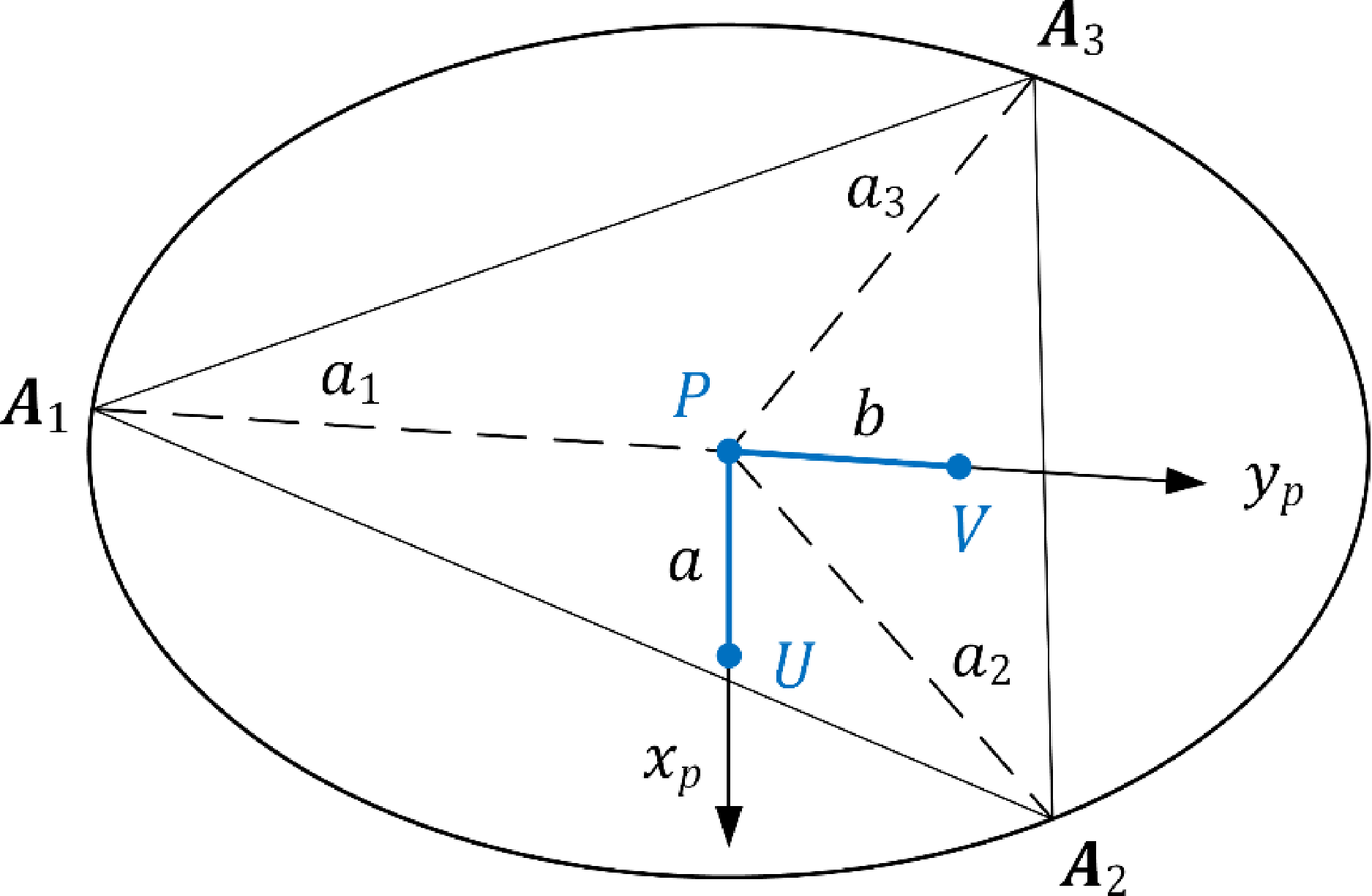
Based on the measurement values of each target point obtained from different observation points, the end pose of the lapping and polishing disk is calculated. Specifically, in the lapping and polishing disk coordinate system P-x P y P z P , three targeted measurement points P, U, and V are set at the center point P and on the x P and y P coordinate axes, respectively. The positional relationship of the measurement points on the lapping and polishing disk is shown in Figure 4.
Measuring points position.

The position vectors of the measurement points U and V under the coupled system P-x P y P z P of the lapping and polishing disk can be expressed as:
 \begin{align} {\boldsymbol{U}}_{P}=\left[\begin{array}{lll} a & 0 & 0 \end{array}\right]^{\mathrm{T}} \, ; \, {\boldsymbol{V}}_{P}=\left[\begin{array}{lll} 0 & b & 0 \end{array}\right]^{\mathrm{T}} \end{align}
Among them, a is the distance between the measurement point P and U, and b is the distance between the measurement point P and V. When the lapping and polishing disk is in the observation configuration k, the position measurement values of the three-measurement points P, U, and V in the coordinate system O-XYZ are expressed as:
 \begin{align} \left\{\begin{array}{l} {\boldsymbol{P}}_{O,k}={\boldsymbol{P}}_{m,k}-{\boldsymbol{O}}_{m,k}=\left[\begin{array}{lll} x_{O,k}^{P} & y_{O,k}^{P} & z_{O,k}^{P} \end{array}\right]^{\mathrm{T}}\\[4pt] {\boldsymbol{U}}_{O,k}={\boldsymbol{U}}_{m,k}-{\boldsymbol{O}}_{m,k}=\left[\begin{array}{lll} x_{O,k}^{U} & y_{O,k}^{U} & z_{O,k}^{U} \end{array}\right]^{\mathrm{T}}\\[4pt] {\boldsymbol{V}}_{O,k}={\boldsymbol{V}}_{m,k}-{\boldsymbol{O}}_{m,k}=\left[\begin{array}{lll} x_{O,k}^{V} & y_{O,k}^{V} & z_{O,k}^{V} \end{array}\right]^{\mathrm{T}} \end{array}\right. \end{align}
It can be seen from the transformation relationship of the position vectors of each measurement point in different coordinate systems.
 \begin{align} \left\{\begin{array}{l} {\boldsymbol{R}}_{P}\cdot {\boldsymbol{U}}_{P}={\boldsymbol{U}}_{O,k}-{\boldsymbol{P}}_{O,k}=\left[x_{k}^{U} y_{k}^{U} z_{k}^{U}\right]^{\mathrm{T}}\\ {\boldsymbol{R}}_{P}\cdot {\boldsymbol{V}}_{P}={\boldsymbol{V}}_{O,k}-{\boldsymbol{P}}_{O,k}=\left[x_{k}^{V} y_{k}^{V} z_{k}^{V}\right]^{\mathrm{T}}\\ {\boldsymbol{R}}_{P}\cdot \left({\boldsymbol{U}}_{P}\times {\boldsymbol{V}}_{P}\right)=\left({\boldsymbol{U}}_{O,k}-{\boldsymbol{P}}_{O,k}\right)\times \left({\boldsymbol{V}}_{O,k}-{\boldsymbol{P}}_{O,k}\right) \end{array}\right. \end{align}
Among them, O m,k is the position measurement value of the coordinate system O-XYZ in the measurement coordinate system O m -x m y m z m . R P is the rotation matrix of the coordinate system P-x P y P z P relative to the coordinate system O-XYZ.
Under the coordinate system O-XYZ, the measurement values of the end pose of the polishing disk are expressed as:
 \begin{align} {\boldsymbol{P}}_{O,k}=\left[x_{m,k}^{P}\, ; \, y_{m,k}^{P} \, ; \, z_{m,k}^{P} \, ; \, \arctan \frac{\left(z_{k}^{U}\cdot x_{k}^{V}-x_{k}^{U}\cdot z_{k}^{V}\right)}{\left(x_{k}^{U}\cdot y_{k}^{V}-y_{k}^{U}\cdot x_{k}^{V}\right)};\arcsin \frac{\left(z_{k}^{U}\cdot y_{k}^{V}-y_{k}^{U}\cdot z_{k}^{V}\right)}{ab};\arctan \frac{a\cdot x_{k}^{V}}{b\cdot x_{k}^{U}}\right] \end{align}
During the measurement process, the number and position distribution of observation points will have a certain impact on the identification accuracy. To ensure that the matrix (
H
T
 $ \cdot{\boldsymbol{H}}$
is of full rank and the independent error source Δ
 $\varepsilon$
k
is identifiable, the number of observation configurations n should satisfy n > p/6, where p denotes the total number of independent error sources to be identified. Since there are 48 independent error sources to be identified, at least 8 observation configurations need to be selected.
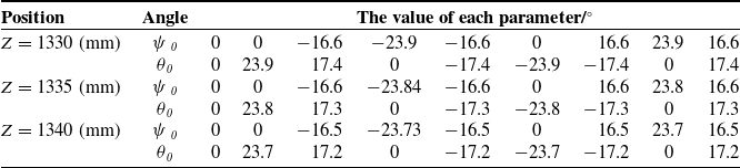
Since the workspace of the prototype is approximately cylindrical, the observation points are selected mainly within the range of the end’s primary movement. To ensure that the observation configurations can traverse all controllable degrees of freedom and make the measurement results reasonable and random to a certain extent, the observation points are uniformly distributed on both the circular ring of the working plane and at the center position. Considering that each independent error source primarily influences the end pose error in the edge area of the workspace, configurations with larger deflection angles around both the X-axis and Y-axis are selected for observation within this plane, thereby effectively improving the signal-to-noise ratio of measurement results.
Pose parameters of observation points.

Therefore, three parallel and equidistant circular surfaces were selected along the Z-axis in the workspace of the mechanism. Nine points were uniformly selected on each circular surface, and a total of 27 poses were used for parameter identification. The pose parameters of the measurement points are shown in Table I.
Before parameter identification, it is necessary to verify the reliability of the identification model. Firstly, the accuracy rate ζ i of parameter identification is defined, which is expressed in Eq. (37).
In the formula, ε ai and ε ai ′ denote the prescribed value and the identified value of the geometric parameter associated with the i-th error source, respectively.
 \begin{align} \zeta _{i}=\frac{\left| \varepsilon _{ai}-\varepsilon _{ai}^{\mathrm{'}}\right| }{\left| \varepsilon _{ai}\right| } \end{align}
Secondly, 16 independent error sources in the branched chain were selected and defined. Based on the error model, the end pose error was analyzed. Finally, the parameter identification of the end pose error was conducted using the identification model, and the results are shown in Tables II and III.
It can be known that the error rate of geometric parameter identification ranges from 0 to 13.21%. Only one erroneous parameter achieves a relatively accurate identification result. However, a high identification error rate will significantly impact the position accuracy of the robot. The main reason for the poor identification accuracy is that during the parameter identification process, which involves tracing the error source, the inverse operation of the matrix (
H
T
 $ \cdot{\boldsymbol{H}}$
is required, and inverting an ill-conditioned matrix often results in low solution accuracy. To analyze and evaluate the solution stability of this identification model, the condition number of the coefficient matrix is utilized as a metric for assessing the degree of ill-conditioning in the linear equation system. Specifically, a larger condition number of the matrix (
H
T
 $ \cdot{\boldsymbol{H}}$
indicates a higher degree of ill-conditioning. When the condition number of the matrix (
H
T
 $ \cdot{\boldsymbol{H}}$
exceeds 103, the identification results become highly sensitive to measurement noise, which may cause significant deviations from the true values. For an arbitrary observed configuration, the calculated condition number is cond (
H
T
⋅H
) = 2.855 × 1036 >> 103. This demonstrates that the robustness of the identification matrix is inadequate. Consequently, even a minor disturbance in (
H
T
 $ \cdot{\boldsymbol{H}}$
can lead to reduced solution accuracy and degraded identification performance.
Identification results of geometric parameters.

Identification results of geometric parameters.

To address this ill-conditioned problem, an improved pivot element weighted iterative algorithm is employed for optimization. The core of this algorithm lies in preprocessing the coefficient matrix by adding a weight to its principal components, thereby reducing the condition number of the coefficient matrix. As the condition number decreases, the degree of ill-conditioning is mitigated. To further enhance the accuracy and stability of the solution, the algorithm is refined. Specifically, an intermediate variable is introduced, and through the error transfer method, the error of the solution vector is transferred to the intermediate variable. Subsequently, the intermediate variable is solved using the principal component weighted iterative method, achieving higher solution accuracy.
The identification model is formulated as the following system of equations.
 \begin{align} {\boldsymbol{Ax}} ={\boldsymbol{b}} \end{align}
Among them,
 $ {\boldsymbol{A}} ={\boldsymbol{H}}^{\mathrm{T}}{\boldsymbol{H}} ;\quad {\boldsymbol{x}}={\unicode{x0394}} \boldsymbol{\varepsilon }_{m} ;\quad {\boldsymbol{b}}={\boldsymbol{H}}^{\mathrm{T}}\delta {\boldsymbol{P}}_{m} $
.
By introducing intermediate variables and setting
 ${\boldsymbol{x}} ={\boldsymbol{c}}{\boldsymbol{y}}$
and
 ${\boldsymbol{c}} ={\boldsymbol{A}}^{\mathrm{T}}$
, where
 ${\boldsymbol{c}}$
is a non-singular matrix, the system of equations can be expressed as:
 \begin{align} \left({\boldsymbol{A}}{\boldsymbol{A}}^{\mathrm{T}}\right){\boldsymbol{y}}={\boldsymbol{b}} \end{align}
Based on the principal component weighting method, the system of equations can be expressed as:
 \begin{align} \left({\boldsymbol{A}}{\boldsymbol{A}}^{\mathrm{T}}+\alpha {\boldsymbol{E}}\right){\boldsymbol{y}}={\boldsymbol{b}}+\alpha {\boldsymbol{y}} \end{align}
Through successive iterations, the iterative equation can be expressed as:
 \begin{align} \left({\boldsymbol{A}}{\boldsymbol{A}}^{\mathrm{T}}+\alpha {\boldsymbol{E}}\right){\boldsymbol{y}}^{\left(\lambda +1\right)}={\boldsymbol{b}}+\alpha {\boldsymbol{y}}^{\lambda } \end{align}
Among them,
 $\lambda$
denotes the number of iterations. Setting
 ${\boldsymbol{y}}^{(\lambda +1)}={\boldsymbol{y}}^{\lambda }+{\boldsymbol{e}}^{\lambda }$
and combining the aforementioned formula, we can be expressed as:
 \begin{align} \left({\boldsymbol{A}}{\boldsymbol{A}}^{\mathrm{T}}+\alpha {\boldsymbol{E}}\right){\boldsymbol{e}}^{\left(\lambda \right)}={\boldsymbol{b}}-{\boldsymbol{A}}{\boldsymbol{A}}^{\mathrm{T}}{\boldsymbol{y}}^{\left(\lambda \right)} \end{align}
When
 ${\boldsymbol{e}}^{(\lambda )}$
is small enough, that is, when
 $\frac{\left\| {\boldsymbol{e}}^{\left(\lambda \right)}\right\| }{\left\| {\boldsymbol{y}}^{\left(\lambda \right)}\right\| }\leq \mu$
, the optimal solution of the equation system can be obtained.
The selection of the weighting factor
 $\alpha$
in the identification model plays a critical role during the iterative process. If
 $\alpha$
is too small, the change in the condition number will be limited, and the equation set will remain ill-conditioned. Conversely, if
 $\alpha$
is too large, it may result in an undesirably slow convergence rate. To achieve faster convergence while maintaining identification accuracy, it is essential to analyze how the condition number cond (
 ${\boldsymbol{A}}{\boldsymbol{A}}^{\mathrm{T}}+\alpha {\boldsymbol{E}}$
) of the identification matrix varies with the weighting factor
 $\alpha$
. The corresponding relationship is illustrated in Figure 5.
The variation law of the condition number with changes in the weighting factor.

In this study,
 $\alpha$
is set to 240, resulting in cond (
 ${\boldsymbol{A}}{\boldsymbol{A}}^{\mathrm{T}}+\alpha {\boldsymbol{E}}$
) = 1.669. It can be observed that the condition number of the coefficient matrix in the identification model has been substantially reduced compared to its value prior to optimization.
Upon determining the value of the weighting factor, the identification algorithm is optimized using the improved principal component weighting iterative method, thereby enabling the solution of the geometric parameters to be identified. The iterative procedure is illustrated in Figure 6.
Flowchart of improved pivot element weighted iterative algorithm.

Similarly, the 16 independent error sources of the branched chain were selected to perform parameter identification using an improved pivot element weighted iterative algorithm model. The identification values and set values were recorded as shown in Figure 7.
The identification value and set value.

Based on the parameter identification results, the error rates of the 16 error sources of the branched chain identified directly by the least squares method and by the improved pivot element weighted iterative algorithm were respectively calculated, and the results are shown in Figure 8.
Error rate of geometric parameter identification.

Error values before and after calibration of the end position.

As shown in Figure 8, the error rate of the improved pivot element weighted iterative algorithm ranges from 0 to 5.122%. Among these, five parameters exhibit a relatively high identification accuracy. Compared with the identification results directly obtained by the least squares method, the error rate of the improved algorithm is significantly reduced, and the amplitude of error fluctuation is obviously decreased. This result indicates that this method can effectively enhance the accuracy of parameter identification results.
4.3. Kinematics calibration and simulation results
In the kinematic calibration process, geometric error sources are identified using the measured end pose errors, and the geometric parameters in the robot controller are modified based on these identification results to improve the robot’s motion accuracy.
On the basis of parameter identification using the improved pivot element weighted iterative algorithm, the end position error is compensated. For this purpose, 27 sets of observation configurations are established on three observation planes, and kinematic calibration is performed. To make the calibrated pose error more intuitive, only the position values in the three translational degrees of freedom are considered, and the results are shown in Figure 9. It can be seen from the result that using the improved pivot element weighted iterative algorithm for calibration significantly reduces the end pose error compared to the error before calibration.
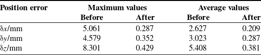
To further validate the reliability of kinematic calibration, Table IV presents the maximum and average values of the end position error before and after calibration. Additionally, the modulus of the position error, also known as the volumetric position error, is utilized to quantify the accuracy of the end pose.
It can be known that the maximum position error has decreased from (5.061, 4.579, 8.301) mm to (0.287, 0.352, 0.429) mm, and the maximum volumetric position error has decreased from 10.747 mm to 0.625 mm. The average position error has decreased from (2.627, 3.023, 5.408) mm to (0.209, 0.287, 0.381) mm, and the average volumetric position error has decreased from 6.729 mm to 0.521 mm. According to the data analysis, based on the improved pivot element weighted iterative algorithm, after kinematic calibration, both the maximum and average values of the end position error have decreased, and the accuracy of the mechanism has significantly improved.
5. Conclusions and future work
Through the calibration of the kinematic parameters of the serial-parallel robot, the motion accuracy of the end-effector has been improved. This paper presents a geometric error model for a class of 5-DOF serial-parallel robots and separates the compensable error sources from the non-compensable ones among the geometric error sources. Based on the measurement results of the end position, the error rate of the improved pivot element weighted iterative algorithm is significantly lower than that of the least squares identification algorithm, and the amplitude of error fluctuation is also markedly reduced. Through the kinematic calibration experiment, the validity of the proposed calibration method was verified. The results show that the maximum volumetric position error after calibration was reduced from 10.747 mm to 0.625 mm, and the average volumetric position error was reduced from 6.729 mm to 0.521 mm.
However, the influence of the clearance of kinematic pairs was not considered when establishing the kinematic model and the error model. Due to the actual existence of the clearance of kinematic pairs, this will lead to motion errors of the mechanism. Therefore, future research will focus on systematically analyzing the impact of joint clearance on both the error model and kinematic performance, aiming to provide deeper insights into improving the accuracy and reliability of the mechanism.
Maximum and average error of the end position before and after calibration.

Author contribution
Bo Sun and Gang Cheng conceived and designed the study. Mingyang Qin conducted data gathering. Yaolin Jiang and Bo Sun performed statistical analyses. Bo Sun wrote the article.
Financial support
The financial support for this work, provided by the National Natural Science Foundation of China (Grant No. 52275039), is gratefully acknowledged.
Competing interests
The authors declare that they have no competing interests.
Ethical approval
Not applicable.