1 Introduction
The most mysterious manifestation of particle–wave duality certainly belongs to the quantum world. Our intuition, formed primarily by experiencing particles and waves at macroscopic scales, appears to be of little use when trying to rationalize the inherent duality of subatomic objects. At the heart of quantum mechanics lies this duality, where electrons are at times waves, diffracting, and at times particles, hitting a screen. Recently, a series of fluid dynamics experiments has provided an interesting example of particle–wave association at the macroscopic scale. The experiments consist of releasing a millimetric drop on the surface of a periodically oscillating bath. Given the right combination of parameters, the drop avoids coalescence by always maintaining an air layer between itself and the free surface (Walker Reference Walker1978). Such a drop can bounce indefinitely on the surface, generating a wavefield around its position. Furthermore, as the parameter controlling the amplitude of the periodic forcing is increased, the drops can be shown to go through an instability and start moving horizontally, giving rise to what are commonly called walkers (Couder et al. Reference Couder, Protiere, Fort and Boudaoud2005). Since the waves are generated by the drops, and the drops propelled by the waves, the system comprises a macroscopic analogy of the pilot-wave theory of quantum mechanics as first conceived by de Broglie (Reference de Broglie1930).
Several studies have further explored the analogies between bouncing drops and quantum mechanics. Couder & Fort (Reference Couder and Fort2006) demonstrated that walkers diffract through single and double slits in a manner reminiscent of electron/photon diffraction (Bach et al. Reference Bach, Pope, Liou and Batelaan2013). Eddi et al. (Reference Eddi, Fort, Moisy and Couder2009), showed that walkers can tunnel through submerged boundaries, analogous to quantum tunnelling. Fort et al. (Reference Fort, Eddi, Boudaoud, Moukhtar and Couder2010) established that, when in a rotating frame, walkers settle into circular orbits of quantized radii, providing an analogy to Landau quantization (see also Harris & Bush Reference Harris and Bush2014; Oza et al. Reference Oza, Harris, Rosales and Bush2014). Labousse (Reference Labousse2014) and Perrard et al. (Reference Perrard, Labousse, Miskin, Fort and Couder2014) examined walker motion in a central force, and reported the emergence of a double quantization in energy and angular momentum. Harris et al. (Reference Harris, Moukhtar, Fort, Couder and Bush2013) studied walkers in a circular bath, and demonstrated the emergence of coherent statistical behaviour similar to what is observed in quantum corrals (Crommie, Lutz & Eigler Reference Crommie, Lutz and Eigler1993).
Central to the understanding of this hydrodynamic pilot-wave system is the concept of memory (Couder & Fort Reference Couder and Fort2006; Eddi et al. Reference Eddi, Sultan, Moukhtar, Fort, Rossi and Couder2011). Every time the drop bounces on the vibrating surface, it generates a wave which decays exponentially in time due to the viscous dissipation. Upon several impacts, the wavefield is thus the accumulation of all contributions from previous impacts. The ability of a drop to ‘remember’ its past depends crucially on the decay rate of the waves. Near the Faraday threshold, the waves decay slowly, and the drop’s dynamics will depend not only on its current position, but also on the position of its previous impacts. This is, in essence, the source of the temporal non-locality displayed by bouncing drops, and represents a key idea in most theoretical models (Couder & Fort Reference Couder and Fort2006; Protière, Boudaoud & Couder Reference Protière, Boudaoud and Couder2006; Eddi et al. Reference Eddi, Sultan, Moukhtar, Fort, Rossi and Couder2011; Moláček & Bush Reference Moláček and Bush2013b ; Oza, Rosales & Bush Reference Oza, Rosales and Bush2013; Labousse Reference Labousse2014).
Despite significant progress in the theoretical understanding of this hydrodynamic pilot-wave system, an important gap still exists: the interaction of walkers with variable topography. Such interactions give rise to apparently non-classical behaviour of the drops and arise in a number of key hydrodynamic quantum analog systems. Therefore an ability to model these interactions will be crucial to better understanding the analogy – and the limitations thereof – between the macroscopic pilot-wave system and its quantum counterpart. Most of the theoretical models developed in the past (see Bush (Reference Bush2015) for a review) focus on baths of effectively infinite depth. A few recent exceptions include Gilet (Reference Gilet2014), Blanchette (Reference Blanchette2016), Dubertrand et al. (Reference Dubertrand, Hubert, Schlagheck, Vandewalle, Bastin and Martin2016) and Nachbin, Milewski & Bush (Reference Nachbin, Milewski and Bush2016). In Nachbin et al. (Reference Nachbin, Milewski and Bush2016) conformal mapping is used to transform a variable topography to a flat one, a technique limited to two dimensions. In Gilet (Reference Gilet2014) and Blanchette (Reference Blanchette2016) the variation in depth is treated as an effective boundary, and the wavefield is decomposed into eigenfunctions of the Laplacian with either a homogenous Neumann (Gilet Reference Gilet2014) or Dirichlet (Blanchette Reference Blanchette2016) boundary condition. Dubertrand et al. (Reference Dubertrand, Hubert, Schlagheck, Vandewalle, Bastin and Martin2016) takes an approach similar to Gilet (Reference Gilet2014) in imposing a homogenous Neumann condition at the effective boundaries, but the equations are solved employing a Green’s function approach instead of an eigenfunction decomposition as in Gilet (Reference Gilet2014).
In this paper we propose a reduced model rich enough to capture the interaction between walkers and variable topography, yet simple enough to allow for efficient numerical simulation and physical transparency. Unlike the works cited in the previous paragraph, the variable depth is treated not as an effective boundary, but as a place where the wave speed changes, providing a mechanism for wave reflection. The model exploits the fact that, because the entire system is driven near resonance, the wavefield is nearly monochromatic and therefore only certain wavenumbers need to be modelled correctly. We show that – with a reasonable quantitative agreement – our model reproduces some important laboratory experiments such as non-specular reflection (Eddi et al. Reference Eddi, Fort, Moisy and Couder2009; Pucci et al. Reference Pucci, Sáenz, Faria and Bush2016b ) and the observed pattern of diffraction past a slit reported in Harris (Reference Harris2015).
2 Model
In this section we present the theoretical model. In § 2.1, we develop a simplified description of the surface waves and in § 2.2 we incorporate the effect of drops bouncing on the surface.
2.1 Surface waves model
We are interested in the surface waves of a bath undergoing a vertical sinusoidal oscillation. In the bath’s frame of reference, the problem is equivalent to considering a time-dependent gravity:
 $g=g_{0}(1+\unicode[STIX]{x1D6E4}\cos (\unicode[STIX]{x1D6FA}t))$
, where
 $g_{0}$
is the gravitational acceleration,
 $\unicode[STIX]{x1D6FA}$
denotes the angular frequency of oscillation and
 $\unicode[STIX]{x1D6E4}$
the amplitude. For a fixed
 $\unicode[STIX]{x1D6FA}$
, there exists a critical amplitude of oscillation,
 $\unicode[STIX]{x1D6E4}_{F}$
, above which the surface becomes unstable. In the nearly inviscid limit of interest to this paper, the instability is always subharmonic, with frequency
 $\unicode[STIX]{x1D714}_{0}=\unicode[STIX]{x1D6FA}/2$
(Benjamin & Ursell Reference Benjamin and Ursell1954; Kumar Reference Kumar1996). The bouncing drop experiments described in the introduction are typically carried out near (and below) the stability boundary, so that the flat surface of the bath is stable, but subharmonic modes excited within it decay very slowly. Furthermore, the drops are small enough that the waves they generate may be treated as linear.
Instead of beginning with the linearized Navier–Stokes equations, we take as a starting point the quasi-potential theory developed in Milewski et al. (Reference Milewski, Galeano-Rios, Nachbin and Bush2015), which when extended to a bath of finite depth is given by
 $$\begin{eqnarray}\displaystyle & \unicode[STIX]{x0394}\unicode[STIX]{x1D719}=0,\quad \text{for }-h(\boldsymbol{x})\leqslant z\leqslant 0, & \displaystyle\end{eqnarray}$$
 $$\begin{eqnarray}\displaystyle & \unicode[STIX]{x1D735}\unicode[STIX]{x1D719}\boldsymbol{\cdot }\boldsymbol{n}=0,\quad \text{for }z=-h(\boldsymbol{x}), & \displaystyle\end{eqnarray}$$
 $$\begin{eqnarray}\displaystyle & \displaystyle \unicode[STIX]{x1D719}_{t}=-g(t)\unicode[STIX]{x1D702}+2\unicode[STIX]{x1D708}^{\ast }\unicode[STIX]{x1D6E5}_{\bot }\unicode[STIX]{x1D719}+\frac{\unicode[STIX]{x1D70E}}{\unicode[STIX]{x1D70C}}\unicode[STIX]{x1D6E5}_{\bot }\unicode[STIX]{x1D702},\quad \text{for }z=0, & \displaystyle\end{eqnarray}$$
 $$\begin{eqnarray}\displaystyle & \unicode[STIX]{x1D702}_{t}=\unicode[STIX]{x1D719}_{z}+2\unicode[STIX]{x1D708}^{\ast }\unicode[STIX]{x1D6E5}_{\bot }\unicode[STIX]{x1D702},\quad \text{for }z=0. & \displaystyle\end{eqnarray}$$
Here
 $\unicode[STIX]{x1D702},\unicode[STIX]{x1D719}$
, denote the free-surface displacement and velocity potential. The parameter
 $\unicode[STIX]{x1D708}^{\ast }$
is an effective kinematic viscosity, chosen to capture the correct stability threshold
 $\unicode[STIX]{x1D6E4}_{F}$
, and
 $\unicode[STIX]{x1D70E},\unicode[STIX]{x1D70C}$
denote surface tension and density. Finally,
 $\boldsymbol{n}$
is a vector normal to the bottom profile,
 $h(\boldsymbol{x})$
the depth of the undisturbed surface, and
 $\unicode[STIX]{x1D6E5}_{\bot }$
the horizontal Laplacian (i.e.
 $\unicode[STIX]{x1D6E5}_{\bot }=\unicode[STIX]{x2202}_{xx}+\unicode[STIX]{x2202}_{yy}$
).
We consider a bath having a deep and a shallow region, separated by a discontinuous jump, so
 $h(\boldsymbol{x})$
is given by:
 $$\begin{eqnarray}h(\boldsymbol{x})=\left\{\begin{array}{@{}ll@{}}h_{0}\quad & \text{for }\boldsymbol{x}\in {\mathcal{D}},\\ h_{1}\quad & \text{for }\boldsymbol{x}\not \in {\mathcal{D}},\end{array}\right.\end{eqnarray}$$
where
 $h_{0}>h_{1}$
. The key feature that we aim to exploit is that the sinusoidal oscillations of the bath favour the resonating temporal frequencies, causing the waves to be nearly monochromatic. Thus we need not model all waves correctly, but only those for which the frequency is approximately
 $\unicode[STIX]{x1D6FA}/2$
; other waves are less important owing to their faster temporal decay.
The main difficulty in solving (2.1)–(2.4) is that
 $\unicode[STIX]{x1D719}_{z}$
in (2.4) couples the surface evolution to Laplace’s equation in the three-dimensional domain, making the problem computationally expensive. When
 $h(\boldsymbol{x})=\text{const.}$
, it can be shown that (see e.g. Whitham Reference Whitham1974)
 $$\begin{eqnarray}{\mathcal{F}}(\unicode[STIX]{x1D719}_{z}(\boldsymbol{x},0,t))=|\boldsymbol{k}|\tanh (|\boldsymbol{k}|h){\mathcal{F}}(\unicode[STIX]{x1D719}(\boldsymbol{x},0,t)),\end{eqnarray}$$
where
 ${\mathcal{F}}$
denotes the two-dimensional Fourier transform in
 $x$
and
 $y$
and
 $\boldsymbol{k}=(k_{x},k_{y})$
is the wavenumber vector. This allows for the surface evolution to be represented, in Fourier space, using only data on the surface, reducing a three-dimensional problem to two dimensions. When
 $h(\boldsymbol{x})$
is not constant, however, no simple explicit representation of
 $\unicode[STIX]{x1D719}_{z}(\boldsymbol{x},0,t)$
in terms of
 $\unicode[STIX]{x1D719}(\boldsymbol{x},0,t)$
exists . Our goal is to approximate
 $\unicode[STIX]{x1D719}_{z}$
in (2.4) using data on the surface only, and to do so in a way that correctly models waves with frequency
 $\unicode[STIX]{x1D714}=\unicode[STIX]{x1D6FA}/2$
.
Motivated by shallow-water theory, we seek an approximation of the form
 $$\begin{eqnarray}\displaystyle \unicode[STIX]{x1D719}_{z}(\boldsymbol{x},0,t)\approx -\unicode[STIX]{x1D735}_{\bot }\boldsymbol{\cdot }(b(\boldsymbol{x})\unicode[STIX]{x1D735}_{\bot }\unicode[STIX]{x1D719}(\boldsymbol{x},0,t)) & & \displaystyle\end{eqnarray}$$
and choose
 $b(\boldsymbol{x})$
to exactly match the dispersion relation of Faraday waves in both the shallow and deep regions. Given
 $\unicode[STIX]{x1D6FA}$
and
 $h_{0},h_{1}$
, we must thus determine the most unstable wavenumber in each region, denoted by
 $k_{F_{0}},k_{F_{1}}$
. Following appendix A of Milewski et al. (Reference Milewski, Galeano-Rios, Nachbin and Bush2015), the Faraday wavenumber in each region of constant depth is computed by finding the
 $k$
which minimizes
 $\unicode[STIX]{x1D6E4}$
in the following expression:
 $$\begin{eqnarray}\displaystyle \left[\unicode[STIX]{x1D714}_{I}^{2}+\unicode[STIX]{x1D6FE}^{2}-{\textstyle \frac{1}{4}}\unicode[STIX]{x1D6FA}^{2}\right]^{2}+\unicode[STIX]{x1D6FA}^{2}\unicode[STIX]{x1D6FE}^{2}-{\textstyle \frac{1}{4}}\unicode[STIX]{x1D714}_{g}^{2}\unicode[STIX]{x1D6E4}^{2}=0, & & \displaystyle\end{eqnarray}$$
where
 $\unicode[STIX]{x1D714}_{I}^{2}(k)=k\tanh (kh)(g_{0}+\unicode[STIX]{x1D70E}/\unicode[STIX]{x1D70C}k^{2})$
is the ideal/inviscid dispersion relation,
 $\unicode[STIX]{x1D6FE}=2\unicode[STIX]{x1D708}^{\ast }k^{2}$
is the dissipation rate and
 $\unicode[STIX]{x1D714}_{g}=g_{0}k\tanh (kh)$
. Notice that this reduces to the well-known result of Benjamin & Ursell (Reference Benjamin and Ursell1954) when
 $\unicode[STIX]{x1D6FE}\rightarrow 0$
, and in that limit
 $k_{F_{0}},k_{F_{1}}$
simply satisfy
 $$\begin{eqnarray}\displaystyle \left(g_{0}+\frac{\unicode[STIX]{x1D70E}}{\unicode[STIX]{x1D70C}}k_{F_{0}}^{2}\right)k_{F_{0}}\tanh (k_{F_{0}}h_{0})=\left(g_{0}+\frac{\unicode[STIX]{x1D70E}}{\unicode[STIX]{x1D70C}}k_{F_{1}}^{2}\right)k_{F_{1}}\tanh (k_{F_{1}}h_{1})=\unicode[STIX]{x1D6FA}/2. & & \displaystyle\end{eqnarray}$$
In order for (2.7) to exactly match the dispersion relation of Faraday waves in the regions of constant depth, we must choose
 $$\begin{eqnarray}b(\boldsymbol{x})=\left\{\begin{array}{@{}ll@{}}\tanh (k_{F_{0}}h_{0})/k_{F_{0}}\quad & \text{for }\boldsymbol{x}\in {\mathcal{D}},\\ \tanh (k_{F_{1}}h_{1})/k_{F_{1}}\quad & \text{for }\boldsymbol{x}\not \in {\mathcal{D}}.\end{array}\right.\end{eqnarray}$$
This leads to the following wave model:
 $$\begin{eqnarray}\displaystyle & \displaystyle \unicode[STIX]{x1D719}_{t}=-g(t)\unicode[STIX]{x1D702}+2\unicode[STIX]{x1D708}^{\ast }\unicode[STIX]{x1D6E5}_{\bot }\unicode[STIX]{x1D719}+\frac{\unicode[STIX]{x1D70E}}{\unicode[STIX]{x1D70C}}\unicode[STIX]{x1D6E5}_{\bot }\unicode[STIX]{x1D702}, & \displaystyle\end{eqnarray}$$
 $$\begin{eqnarray}\displaystyle & \unicode[STIX]{x1D702}_{t}=-\unicode[STIX]{x1D735}_{\bot }\boldsymbol{\cdot }(b(\boldsymbol{x})\unicode[STIX]{x1D735}_{\bot }\unicode[STIX]{x1D719})+2\unicode[STIX]{x1D708}^{\ast }\unicode[STIX]{x1D6E5}_{\bot }\unicode[STIX]{x1D702}, & \displaystyle\end{eqnarray}$$
where
 $b$
is given by (2.10).
It is worth noting that in the long-wave limit (i.e.
 $kh\rightarrow 0$
), we have that
 $b=h$
and formally the linear shallow-water theory is recovered. Our approximation, however, does not rely on
 $k_{F_{0}}h_{0}\ll 1$
, which is not typically true for the bouncing drop experiments, but on the assumption that the wavefield is nearly monochromatic, with all the energy in modes of temporal frequency near
 $\unicode[STIX]{x1D6FA}/2$
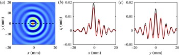
. For drops bouncing periodically over a vibrating bath, parametric resonance ensures that such an approximation is justifiable, as later shown in the quantitative comparison performed in figure 1. In the next section we modify the wave model given by (2.11)–(2.12) in order to account for a drop bouncing on its surface.
(a) Comparison between our approximation (
 $y>0$
), and the quasi-potential theory (
 $y<0$
) of Milewski et al. (Reference Milewski, Galeano-Rios, Nachbin and Bush2015) for a walker using exactly the same parameters. (b,c) Show the
 $x$
and
 $y$
cross-sections of the wavefield. The red line represents the quasi-potential theory, and the black line our model. Here
 $R=0.38~\text{mm}$
,
 $\unicode[STIX]{x1D6E4}/\unicode[STIX]{x1D6E4}_{F}=0.9$
, and the drop is located at the origin.

2.2 Drop dynamics and wave/drop coupling
The wave–drop coupling is identical to that of Moláček & Bush (Reference Moláček and Bush2013b ) and Milewski et al. (Reference Milewski, Galeano-Rios, Nachbin and Bush2015), where the drop is treated as an excess pressure on the dynamic surface condition. This leads to the following system:
 $$\begin{eqnarray}\displaystyle & \displaystyle \unicode[STIX]{x1D719}_{t}=-g(t)\unicode[STIX]{x1D702}+\frac{\unicode[STIX]{x1D70E}}{\unicode[STIX]{x1D70C}}\unicode[STIX]{x1D6E5}_{\bot }\unicode[STIX]{x1D702}+2\unicode[STIX]{x1D708}^{\ast }\unicode[STIX]{x1D6E5}_{\bot }\unicode[STIX]{x1D719}-\frac{1}{\unicode[STIX]{x1D70C}}P_{D}(\boldsymbol{x}-\boldsymbol{x}_{p}(t),t), & \displaystyle\end{eqnarray}$$
 $$\begin{eqnarray}\displaystyle & \displaystyle \unicode[STIX]{x1D702}_{t}=-\unicode[STIX]{x1D735}_{\bot }\boldsymbol{\cdot }(b\unicode[STIX]{x1D735}_{\bot }\unicode[STIX]{x1D719})+2\unicode[STIX]{x1D708}^{\ast }\unicode[STIX]{x1D6E5}_{\bot }\unicode[STIX]{x1D702}. & \displaystyle\end{eqnarray}$$
The new term
 $P_{D}$
represents the effect of the drop, and
 $\boldsymbol{x}_{p}$
denotes the drop’s horizontal position, which evolves according to
 $$\begin{eqnarray}m\frac{\text{d}^{2}\boldsymbol{x}_{p}}{\text{d}t^{2}}+\left(c_{4}\sqrt{\frac{\unicode[STIX]{x1D70C}R_{0}}{\unicode[STIX]{x1D70E}}}F(t)+6\unicode[STIX]{x03C0}R_{0}\unicode[STIX]{x1D707}_{air}\right)\frac{\text{d}\boldsymbol{x}_{p}}{\text{d}t}=-F(t)\unicode[STIX]{x1D735}\unicode[STIX]{x1D702}|_{\boldsymbol{x}=\boldsymbol{x}_{p}}.\end{eqnarray}$$
The parameters
 $m,R_{0},\unicode[STIX]{x1D707}_{\mathit{air}}$
and
 $c_{4}$
denote the drop mass, drop radius, air viscosity and coefficient of tangential restitution, respectively (Moláček & Bush Reference Moláček and Bush2013b
). The function
 $F(t)$
represents the reaction force exerted on the drop by the fluid.
Calculating
 $F(t)$
requires solving for the vertical dynamics of the particle, which, as shown in Moláček & Bush (Reference Moláček and Bush2013a
) can be well approximated by a logarithmic spring during contact. Although it is possible to couple the wave model here presented to the log-spring model of Moláček & Bush (Reference Moláček and Bush2013a
), for the sake of simplicity we assume that the drop bounces periodically, with period
 $T_{F}=4\unicode[STIX]{x03C0}/\unicode[STIX]{x1D6FA}$
. It can then be shown (see Moláček & Bush Reference Moláček and Bush2013b
) that
 $\int _{t}^{t+T_{F}}F(\unicode[STIX]{x1D70F})\,\text{d}\unicode[STIX]{x1D70F}=mg_{0}T_{F}$
. Assuming that the contact time is small enough (relative to the bouncing period) that
 $F$
may be treated as an impulse force, and taking the impacts to happen at
 $t=nT_{F}$
, we obtain
 $F(t)=mg_{0}\sum _{n=0}^{\infty }\unicode[STIX]{x1D6FF}(t-nT_{F}/T_{F})$
, where
 $\unicode[STIX]{x1D6FF}$
is the Dirac delta function. This eliminates the need to solve for the vertical motion of the drop; however, by considering the impact to be instantaneous, the model ignores the evolution of the waves during contact, which may be important for certain types of interaction given that the contact time can be as large as one-fourth of the period. Finally the excess pressure
 $P_{D}$
may be modelled as
 $P_{D}(\boldsymbol{x}-\boldsymbol{x}_{p},t)=F(t)I(\Vert \boldsymbol{x}-\boldsymbol{x}_{p}\Vert )$
, where
 $I$
describes the spatial distribution of the excess pressure (and has units of
 $1/\text{length}^{2}$
).
It is now convenient to non-dimensionalize the equations using a representative length scale,
 $\unicode[STIX]{x1D706}_{F}$
, and time scale
 $T_{F}$
. Using tildes for dimensionless variables, we obtain
 $$\begin{eqnarray}\displaystyle & \displaystyle \tilde{\unicode[STIX]{x1D719}}_{\tilde{t}}=-G(1+\unicode[STIX]{x1D6E4}\cos (4\unicode[STIX]{x03C0}\tilde{t}-\unicode[STIX]{x1D711}))\tilde{\unicode[STIX]{x1D702}}+\frac{2}{Re}\unicode[STIX]{x0394}\tilde{\unicode[STIX]{x1D719}}+Bo\unicode[STIX]{x0394}\tilde{\unicode[STIX]{x1D702}}-MG\mathop{\sum }_{n=0}^{\infty }\unicode[STIX]{x1D6FF}(\tilde{t}-n)\tilde{I} (\Vert \tilde{\boldsymbol{x}}-\tilde{\boldsymbol{x}}_{p}\Vert ), & \displaystyle \nonumber\\ \displaystyle & & \displaystyle\end{eqnarray}$$
 $$\begin{eqnarray}\displaystyle & \displaystyle \tilde{\unicode[STIX]{x1D702}}_{\tilde{t}}=-\unicode[STIX]{x1D735}\boldsymbol{\cdot }(\tilde{b}\unicode[STIX]{x1D735}\tilde{\unicode[STIX]{x1D719}})+\frac{2}{Re}\unicode[STIX]{x0394}\tilde{\unicode[STIX]{x1D702}}, & \displaystyle\end{eqnarray}$$
where
 $G=g_{0}T_{F}^{2}/\unicode[STIX]{x1D706}_{F}$
,
 $Re=\unicode[STIX]{x1D706}_{F}^{2}/(t_{0}\unicode[STIX]{x1D708})$
,
 $Bo=\unicode[STIX]{x1D70E}T_{f}^{2}/(\unicode[STIX]{x1D70C}\unicode[STIX]{x1D706}_{F}^{3})$
,
 $M=m/(\unicode[STIX]{x1D70C}\unicode[STIX]{x1D706}_{F}^{3})$
,
 $\tilde{b}=b/\unicode[STIX]{x1D706}_{F}$
and
 $\unicode[STIX]{x1D711}$
denotes the impact phase. Similarly (2.15) becomes
 $$\begin{eqnarray}\frac{\text{d}^{2}\tilde{\boldsymbol{x}}_{p}}{\text{d}\tilde{t}^{2}}+\left(C_{i}\mathop{\sum }_{n=0}^{\infty }\unicode[STIX]{x1D6FF}(\tilde{t}-n)+C_{\mathit{air}}\right)\frac{\text{d}\tilde{\boldsymbol{x}}_{p}}{\text{d}\tilde{t}}=-G\mathop{\sum }_{n=0}^{\infty }\unicode[STIX]{x1D6FF}(\tilde{t}-n)\unicode[STIX]{x1D735}\tilde{\unicode[STIX]{x1D702}}|_{\tilde{\boldsymbol{ x}}=\tilde{\boldsymbol{x}}_{p}},\end{eqnarray}$$
where
 $C_{i}=c_{4}\sqrt{\unicode[STIX]{x1D70C}R_{0}/\unicode[STIX]{x1D70E}}gT_{F}$
and
 $C_{\mathit{air}}=6\unicode[STIX]{x03C0}R_{0}\unicode[STIX]{x1D707}_{\mathit{air}}T_{F}/m$
.
The last simplification comes from considering a point impact:
 $\tilde{I} (\tilde{\boldsymbol{x}}-\tilde{\boldsymbol{x}}_{p})=\unicode[STIX]{x1D6FF}(\tilde{\boldsymbol{x}}-\tilde{\boldsymbol{x}}_{p})$
. Equations (2.16)–(2.18) represent the final form of our model, and the rest of this paper is devoted to their study. Henceforth, we drop the tilde notation, but all variables are assumed dimensionless unless otherwise stated.
3 Numerical results
We solve (2.16)–(2.18) numerically using a pseudo-spectral method in space, and fourth-order Runge–Kutta scheme for the time integration. Because of the temporal delta functions, we resolve the drop/surface interaction analytically during impact. That is, at
 $t_{i}=1,2,\ldots$
we modify
 $\unicode[STIX]{x1D719}$
and
 $\boldsymbol{x}_{p}$
by integrating our equations from immediately before until immediately after the impact (see appendix A for details on the numerical algorithm). Doing so allows for high-order accuracy in time without having to resolve the details of the drop/bath interaction. Convergence tests performed indicate that indeed fourth-order accuracy is achieved, and that the results do not depend substantially on the number of spectral modes employed (appendix B).
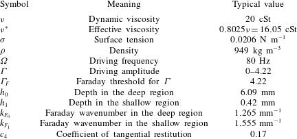
For the numerical simulations that follow, we choose parameters appropriate for a fluid of 20 cSt shaking at a frequency of 80 Hz. Surface tension is
 $0.0206~\text{N}~\text{m}^{-1}$
, and the density is
 $949~\text{kg}~\text{m}^{-3}$
. In the deep region the depth is
 $h_{0}=6.09~\text{mm}$
. When obstacles are present the depth above them is (unless otherwise indicated)
 $h_{1}=0.42~\text{mm}$
, chosen to correspond roughly to the experiments of Harris (Reference Harris2015) and Pucci et al. (Reference Pucci, Sáenz, Faria and Bush2016b
). Computing
 $k_{F}$
using the method outlined in § 2.1 yields
 $k_{F_{0}}\approx 1.265~\text{mm}^{-1}$
and
 $k_{F_{1}}\approx 1.555~\text{mm}^{-1}$
;
 $b(\boldsymbol{x})$
is then computed using (2.10). In order to compare our simulations to available experiments, two different drop sizes are considered: in §§ 3.1 and 3.2 the drops have a radius of 0.39 mm, while in § 3.3 they have a radius of 0.335 mm. The coefficient of tangential restitution
 $c_{4}$
is taken to be 0.17, as suggested in Moláček & Bush (Reference Moláček and Bush2013b
) for a bath of 20 cSt shaking at 80 Hz. Finally, the effective viscosity is
 $\unicode[STIX]{x1D708}^{\ast }=0.8025\unicode[STIX]{x1D708}$
, which yields
 $\unicode[STIX]{x1D6E4}_{F}=4.22$
as the Faraday threshold for the fluid considered. The computations were performed on a domain of (dimensionless) size
 $64\times 64$
using
 $512\times 512$
points, which was sufficient to guarantee resolution-independent results (see appendix B). All parameters used are summarized in table 1.
Physical parameters used in the simulations.

We present below three examples that illustrate the capabilities of the model. First, in § 3.1, we briefly study the dynamics of a drop in a bath of constant depth. We then explore in § 3.2 the interaction of walkers with a planar submerged step, demonstrating that our model captures many of the important features of walker reflection. Finally, we present in § 3.3 results of diffraction past a single slit.
3.1 Constant depth
We consider first walkers in a uniform bath as a benchmark for the model. As expected, in the absence of barriers the drops move at a constant speed that is independent of the initial conditions. For any fixed set of physical parameters, the final free-space velocity will depend only on the impact phase
 $\unicode[STIX]{x1D711}$
. Because we have chosen not to consider the details of the vertical dynamics,
 $\unicode[STIX]{x1D711}$
is extraneous to the model and may therefore be treated as a free parameter. As in previous strobed models that average out the vertical dynamics (e.g. Oza et al.
Reference Oza, Rosales and Bush2013; Labousse Reference Labousse2014),
 $\unicode[STIX]{x1D711}$
is chosen so that the theoretical walking speed approximately agrees with the experimentally reported value. A summary of the average experimental walking speed, as well as the inferred impact phase used for all configurations reported in this paper can be found in table 2.
Experimentally measured speed,
 $v$
, at different memories for the two drop sizes considered in this paper. The phase
 $\unicode[STIX]{x1D711}$
is obtained by requiring the numerically observed speed to match the experimental value, and is in the range consistent with experimental observation (Moláček & Bush Reference Moláček and Bush2013a
).

The first comparison we perform is between our model and the equations that are intended to approximate, specifically (2.1)–(2.4). We show in figure 1 the wavefield generated by a walker using our nearly monochromatic approximation, and compare it to the wavefield obtained when using the quasi-potential theory of Milewski et al. (Reference Milewski, Galeano-Rios, Nachbin and Bush2015). Although the match is not perfect, the overall wave features appear to be correctly captured. This indicates that, at least in places of constant depth, where it is easy to solve for
 $\unicode[STIX]{x1D719}_{z}(\boldsymbol{x},0,t)$
exactly using (2.6), our monochromatic approximation
 $\unicode[STIX]{x1D719}_{z}(\boldsymbol{x},0,t)\approx \unicode[STIX]{x1D735}\boldsymbol{\cdot }(b\unicode[STIX]{x1D735}\unicode[STIX]{x1D719}(\boldsymbol{x},0,t))$
performs reasonably well. In the next sections, when considering a variable bottom topography, it becomes very difficult to solve (2.1)–(2.4); therefore, in § 3.2 we instead compare our model to experimental observations of Harris (Reference Harris2015) and Pucci et al. (Reference Pucci, Sáenz, Faria and Bush2016b
).
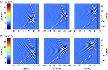
Wave amplitude (contour plot) and trajectories (white line) for wall reflection. The black line at
 $x=50$
divides the deep (
 $x<50$
) and shallow (
 $x>50$
) regions. The leftmost and rightmost images are taken 60 bounces before and after the turning point, respectively. The centre images depict the wavefield exactly at the turning point. The red line represents the corresponding experimental data (Pucci et al.
Reference Pucci, Sáenz, Faria and Bush2016b
). (a)
 $\unicode[STIX]{x1D6E4}/\unicode[STIX]{x1D6E4}_{F}=0.90$
, (b)
 $\unicode[STIX]{x1D6E4}/\unicode[STIX]{x1D6E4}_{F}=0.99$
.

3.2 Reflection from planar boundary
We consider now one of the simplest types of walker–boundary interactions: reflection from a planar submerged obstacles, and compare two of our trajectories to the experimental data of Pucci et al. (Reference Pucci, Sáenz, Faria and Bush2016b
). The simulation consists of sending a walker towards a shallower region at a given incident angle and then recording both the trajectory and the wavefield for several hundred impacts. The walker–boundary interaction can be divided into three distinct stages, depicted in figure 2 for two different values of
 $\unicode[STIX]{x1D6E4}/\unicode[STIX]{x1D6E4}_{F}$
. First, at sufficient distance from the shallow region (
 $x>50~\text{mm}$
in figure 2), the walker does not feel the presence of the step, and therefore moves in a straight line. Then, as it approaches the barrier, its reflected waves start to affect the dynamics, eventually causing the walker to turn around. The drop continues to interact with the submerged step through its wavefield as it moves away from it: the trajectory appears to curve towards the step, becoming asymptotic to a rectilinear motion. At high memory (figure 2
b), we also see the formation of interference fringes caused by the reflected waves. Finally, we observe that although the model approximately captures the correct reflection angle (experimental and numerical lines are nearly parallel in figure 2), the details of the trajectory near the wall are slightly different from the experiments, where the experimental trajectories turn more sharply. Interestingly, the reflection is non-specular (i.e. incident and reflected angles are not equal), and there is a small preferred range of reflected angles. A detailed study of the walker’s non-specular reflection, as well as a more through comparison between the theory here developed and experiments, is reported in Pucci et al. (Reference Pucci, Sáenz, Faria and Bush2016b
). We also see in figure 2 that, as expected, the waves have a much smaller amplitude in the shallow region (
 $x>50$
) than in the deep region (
 $x<50$
). However, neither
 $\unicode[STIX]{x1D702}_{x}$
nor
 $\unicode[STIX]{x1D702}$
appears to be zero at the deep–shallow interface. This inference, consistent with the schlieren imaging of Eddi et al. (Reference Eddi, Fort, Moisy and Couder2009) and Damiano et al. (Reference Damiano, Brun, Harris, Galeano-Rios and Bush2016), suggests that imposing an effective Dirichlet or Neumann boundary condition on the wavefield at places where the depth changes is likely to be inadequate.
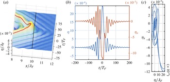
Behaviour of the wavefield at the interface between the shallow (0.42 mm) and the deep (6.09 mm) regions. In (a) we plot the
 $x$
cross-section of the wavefield of a walker impinging perpendicularly upon a step, as a function of time. The walker’s trajectory is given by
 $(x(t),0)$
), and is shown in red. In (b) we plot both
 $\unicode[STIX]{x1D702}$
and its normal derivative,
 $\unicode[STIX]{x1D702}_{x}$
. In (c) we show the relation between
 $\unicode[STIX]{x1D702}$
and
 $\unicode[STIX]{x1D702}_{x}$
at
 $(x,y)=(10,0)$
through the reflection process.

In order to study in more detail what happens to
 $\unicode[STIX]{x1D702}$
at the deep–shallow interface, we consider in figure 3 a walker impinging perpendicularly upon the step. The drop’s trajectory remains orthogonal to the step at all times, allowing for an easier study of the waves by focusing on the
 $x$
cross-section of the wavefield. We show in figure 3(a) the
 $x$
cross-section of the wavefield as a function of time (i.e.
 $\unicode[STIX]{x1D702}(x,0,t)$
), where
 $t=0$
has been chosen as the time where the drop turns away from the shallow region. We see that within about 1.5 wavelengths into the shallow region the wave amplitude has already decayed to nearly zero. The behaviour of
 $\unicode[STIX]{x1D702}$
above the step, indicated by the black line in the figure, suggests that neither
 $\unicode[STIX]{x1D702}=0$
nor
 $\unicode[STIX]{x1D702}_{x}=0$
holds at the deep–shallow interface. This is better seen in figure 3(b), where we plot
 $\unicode[STIX]{x1D702}$
and
 $\unicode[STIX]{x1D702}_{x}$
at
 $(x,y)=(10,0)$
(i.e. above the step) as a function of time. We see that, as the drop approaches the wall, the wave height above the step (blue curve in figure 3
b) oscillates in time, indicating the presence of a transmitted wave.
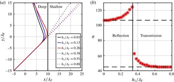
Interaction between a walker and a submerged step as a function of the depth above the step. In (a) we show a few trajectories for depths ranging from very shallow (
 $h_{1}\approx 0.01\unicode[STIX]{x1D706}_{F}$
) to very deep (
 $h_{1}\approx 0.9\unicode[STIX]{x1D706}_{F}$
). In (b) we show the final angle, measured relative to the
 $x$
-axis, as a function of the step’s depth. The vertical solid line separates the drops which were reflected from the drops which were transmitted. The dashed horizontal lines indicate the asymptotic angles for either very shallow or very deep regions.

The relationship between
 $\unicode[STIX]{x1D702}$
and
 $\unicode[STIX]{x1D702}_{x}$
at the deep–shallow interface, plotted in figure 3(c), appears to be rather complex. If the variable depth in the fluid were to be modelled by means of an effective boundary condition of the Robin type, i.e.
 $\unicode[STIX]{x1D6FC}\unicode[STIX]{x1D702}+\unicode[STIX]{x1D6FD}\unicode[STIX]{x2202}\unicode[STIX]{x1D702}/\unicode[STIX]{x2202}n=\unicode[STIX]{x1D705}$
, then figure 3(c) should show (at least approximately) a straight line; for the depth ratio considered in figure 3, this is not the case. Thus, in the context of our model, an effective boundary condition of the Robin type cannot be used in lieu of the spatially varying coefficient in the partial differential equation (PDE) without sacrificing quantitative agreement, and a more complex boundary condition must be sought. Of course, it may very well be that in certain limits (e.g. as
 $h_{1}\rightarrow 0$
) the relation between
 $\unicode[STIX]{x1D702}$
and
 $\unicode[STIX]{x1D702}_{x}$
becomes simple, and an effective boundary of the Robin type becomes appropriate.
We also use the model to investigate the effect of the height above the step on the trajectory. In figure 4 we consider a walker coming from a deep region (
 $h_{0}=6.09~\text{mm}$
) and impinging upon a step at an angle of
 $45^{\circ }$
. We vary the depth above the step between 0.05 mm and 6.09 mm by small increments, and then calculate the final angle after the walker has interacted with the step. We see that the final angle appears to asymptote to a constant for either very shallow or very deep steps. The drops is unable to feel the bottom (i.e. the trajectories do not significantly deviate from a straight line) for depths larger than
 ${\approx}0.6\unicode[STIX]{x1D706}_{F}$
. For depths less than
 ${\approx}0.2\unicode[STIX]{x1D706}_{F}$
, we also see that the reflection angle depends only weakly on the depth. This observation, consistent with experiments (G. Pucci, private communication, 2016), suggests that as long as the depth above the obstacles is small enough, the drop’s interaction with boundaries will be largely independent of the depth in the shallow region.
3.3 Diffraction by a slit
We now briefly consider the case of a walker launched towards a slit. If the drop behaved like a classical macroscopic particles, we would expect its trajectory to remain unaffected by the passage through a slit. In Couder & Fort (Reference Couder and Fort2006), it was shown that this is not the case: passage through a slit deflects the drop owing to the interaction of its wavefield and the barrier. It was found that walkers behaved (on average) much like a plane wave diffracted through a slit. Subsequent experiments conducted by Andersen et al. (Reference Andersen, Madsen, Reichelt, Ahl, Lautrup, Ellegaard, Levinsen and Bohr2015), Harris (Reference Harris2015) and Batelaan et al. (Reference Batelaan, Jones, Huang and Bach2016), were unable to reproduce the precise diffraction pattern observed in Couder & Fort (Reference Couder and Fort2006). Nevertheless, walker deflection was apparent in all of them. Harris (Reference Harris2015) found that, in the absence of external air currents, the single-slit trajectories were dominated by two preferred angles similar to those emerging in the reflection experiments. We proceed by showing that our numerical simulations are consistent with the findings reported in Harris (Reference Harris2015).
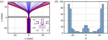
Single-slit diffraction. In (a) we show the particle trajectories, colour coded according to the impact parameter. In (b) we plot the histogram of the deflection angle, measured with respect to the
 $y$
-axis.

The bath topography consists of a deep region of depth
 $h_{0}=6.09~\text{mm}$
, and shallow region, in the shape of a slit, of depth
 $h_{1}=0.42~\text{mm}$
(see figure 5). The width and breadth of the slit are respectively 15 mm and 5 mm wide. Letting
 $x_{i}$
be the distance of the initial position of the drop from the centre of the slit, we took a uniform sample of trajectories with impact parameters ranging from 0 mm to 7.5 mm by increments of 0.025 mm (300 cases in total). Trajectories with
 $x_{i}>6.375~\text{mm}$
reflected from the barrier, and were thus discarded. All simulations started at
 $y=-75~\text{mm}$
, which ensures that a steady walking state is achieved prior to interaction with the slit. We set
 $\unicode[STIX]{x1D6E4}/\unicode[STIX]{x1D6E4}_{F}=0.99$
, and considered a drop of radius 0.335 mm, corresponding to the parameters examined by Harris (Reference Harris2015).
In figure 5(a) we show a few sample trajectories of our numerical simulations. The slit appears to focus trajectories inside it: its width plays an important role in the dynamics. The observed pattern does not appear to be of the classical wave diffraction type; in fact, most trajectories settle to a small range of angles
 $\unicode[STIX]{x1D703}$
after passing through the slit, which is reminiscent of the planar wall reflection and consistent with the findings reported in Harris (Reference Harris2015). Plotting a histogram of the final angle of each trajectory (figure 5
b), indicates a strong preference for
 $55^{\circ }<\unicode[STIX]{x1D703}<65^{\circ }$
, which is similar to the preferred angle observed in Harris (Reference Harris2015). The number of bins in figure 5(b) was chosen to be approximately
 $\sqrt{N}$
, where
 $N$
is the number of trajectories considered. The main qualitative feature of the histogram, i.e. its lateral peaks, remains unaffected by variations in bin size. A thorough comparison between our model and recent single- and double-slit experiments will be reported in Pucci et al. (Reference Pucci, Harris, Faria and Bush2016a
).
4 Conclusions
We have presented a model capable of capturing many interesting features of walker–topography interactions. The model treats depth changes in the fluid not as boundaries, but as regions where the wave speed changes, effectively creating a mechanism for partial wave reflection. Although our equations are reminiscent of a long-wave approximation, we demonstrate that the model remains useful outside the shallow-water limit provided the system is driven near resonance, and the drop is synchronized with its Faraday wavefield.
The assumption that the drop’s vertical motion is periodic, and in resonance with the Faraday waves, might limit the applicability of the model to resonant walkers. In fact, even drops in the resonant
 $(2,1)$
modes may alter their vertical motion, or even violate the periodic assumption, when interacting with other drops or obstacles. Surprisingly, a reasonable agreement is still observed in practice (e.g. figure 2), even though we neglect the vertical dynamics. Inclusion of vertical dynamics into our model is a possible direction of future research.
Our treatment of the variable topography captures the important properties of the reflected waves without a need to explicitly impose a boundary condition. Although it would be interesting to develop a systematic understanding of the reflected Faraday wave, the viscous dissipation and time-dependent gravity are likely to make a rigorous analysis of the reflection and transmission laws at a depth discontinuity extremely challenging, even in the context of our simplified model. Direct numerical simulations of (2.1)–(2.4) are also a possible future direction to better understand the Faraday pilot waves over variable topography, although the computational cost of such a task is likely to be daunting.
The choice of
 $b(\boldsymbol{x})$
given by (2.10) was made so as to correctly capture the phase velocity of the Faraday waves. The approximation of
 $\unicode[STIX]{x1D719}_{z}$
given by (2.7), however, is too simple to allow for the model to also capture the group velocity of the Faraday waves correctly. Interestingly, as shown in the comparison presented in figure 1, the group velocity of the Faraday waves does not appear to fundamentally affect the structure of the drop/pilot-wave ensemble. Employing more sophisticated approximations to
 $\unicode[STIX]{x1D719}_{z}$
that also capture the group velocity of the Faraday waves is likely to improve the quantitative agreement with the quasi-potential theory of Milewski et al. (Reference Milewski, Galeano-Rios, Nachbin and Bush2015), and is a direction currently being pursued.
Finally, we note that all nonlinearities in this hydrodynamic system arise from the particle–wave coupling, which gives rise to complex behaviour that is neither particle-like nor wave-like. The precise nature of the coupling is thus extremely import, and cannot be overlooked in any pilot-wave theory. Although the recent experiments of Andersen et al. (Reference Andersen, Madsen, Reichelt, Ahl, Lautrup, Ellegaard, Levinsen and Bohr2015) and Harris (Reference Harris2015) do not yield the specific diffraction pattern reported in Couder & Fort (Reference Couder and Fort2006), it is clear that particle–wave duality is at the of heart of the bouncing drops’ quantum-like features. For example, trajectories deflecting past a slit give clear evidence of the dual nature of bouncing drops. The relevance of this classical wave–particle duality to quantum mechanics remains, of course, an open question. Nevertheless, bouncing drops do provide an enticing physical picture, even if only at the level of analogy, of what may be happening at scales that we cannot yet probe.
Acknowledgements
I am grateful to J. Bush, A. Kasimov, A. Nachbin, and R. Rosales for fruitful discussions. I would also like to thank G. Pucci and P. Saenz for making their experimental data available. Lastly, I would like to thank the anonymous referees for their valuable comments and suggestions.
Appendix A. Details of numerical algorithm
In this section we explain how the governing equations are solved numerically. The (dimensionless) particle–wave system considered is governed by (see § 2.2):
 $$\begin{eqnarray}\displaystyle & \displaystyle \unicode[STIX]{x1D719}_{t}=-G(1+\unicode[STIX]{x1D6E4}\cos (4\unicode[STIX]{x03C0}t-\unicode[STIX]{x1D711}))\unicode[STIX]{x1D702}+\frac{2}{Re}\unicode[STIX]{x0394}\unicode[STIX]{x1D719}+Bo\unicode[STIX]{x0394}\unicode[STIX]{x1D702}-MG\unicode[STIX]{x1D6FF}(\boldsymbol{x}-\boldsymbol{x}_{p})f(t), & \displaystyle\end{eqnarray}$$
 $$\begin{eqnarray}\displaystyle & \displaystyle \unicode[STIX]{x1D702}_{t}=-\unicode[STIX]{x1D735}\boldsymbol{\cdot }(b\unicode[STIX]{x1D735}\unicode[STIX]{x1D719})+\frac{2}{Re}\unicode[STIX]{x0394}\unicode[STIX]{x1D702}, & \displaystyle\end{eqnarray}$$
 $$\begin{eqnarray}\displaystyle & \displaystyle \frac{\text{d}^{2}\boldsymbol{x}_{p}}{\text{d}t^{2}}+(C_{i}f(t)+C_{\mathit{air}})\frac{\text{d}\boldsymbol{x}_{p}}{\text{d}t}=-Gf(t)\unicode[STIX]{x1D735}\unicode[STIX]{x1D702}|_{\boldsymbol{x}=\boldsymbol{x}_{p}}, & \displaystyle\end{eqnarray}$$
where
 $f(t)=\sum _{n=0}^{\infty }\unicode[STIX]{x1D6FF}(t-n)$
. Since the impacts are instantaneous (i.e.
 $f(t)$
is a sum of delta functions), it is convenient to divide the time evolution in two parts: impact and free flight. The algorithm consists of two main routines: one which evolves the particles and the waves during free flight, and another which resolves the details of the impact.
During free flight the wave evolution is solved using a (Fourier) pseudo-spectral method in space. Taking the Fourier transform of (A 1)–(A 2), and assuming
 $t\neq 1,2,\ldots$
so that
 $f=0$
, yields
 $$\begin{eqnarray}\displaystyle & \displaystyle \hat{\unicode[STIX]{x1D719}}_{t}=-G(t)\hat{\unicode[STIX]{x1D702}}-\frac{2k^{2}}{Re}\hat{\unicode[STIX]{x1D719}}-Bo\,k^{2}\hat{\unicode[STIX]{x1D702}}, & \displaystyle\end{eqnarray}$$
 $$\begin{eqnarray}\displaystyle & \displaystyle \hat{\unicode[STIX]{x1D702}}_{t}=-\text{i}\boldsymbol{k}\boldsymbol{\cdot }\widehat{(b\unicode[STIX]{x1D735}\unicode[STIX]{x1D719})}-\frac{2k^{2}}{Re}\hat{\unicode[STIX]{x1D702}}. & \displaystyle\end{eqnarray}$$
The time evolution of the waves is carried in Fourier space by a standard fourth-order Runge–Kutta method (e.g. LeVeque Reference Leveque2007). The topography enters through the term
 $\widehat{(b\unicode[STIX]{x1D735}\unicode[STIX]{x1D719})}$
, which is numerically computed pseudo-spectrally in the following way:
 $$\begin{eqnarray}\displaystyle {\mathcal{F}}[b(\boldsymbol{x})\unicode[STIX]{x1D735}\unicode[STIX]{x1D719}]={\mathcal{F}}[b(\boldsymbol{x}){\mathcal{F}}^{-1}[\text{i}\boldsymbol{k}{\mathcal{F}}[\unicode[STIX]{x1D719}]]]. & & \displaystyle\end{eqnarray}$$
For the topography considered in the paper,
 $b(\boldsymbol{x})$
is a discontinuous function, and the Fourier transform in (A 6) will be subject to the well-known Gibbs phenomenon. Although in principle this could generate numerical stability problems and/or degrade the accuracy of the algorithm, we observed that in practice the damping provided by the viscous terms in (A 1)–(A 2) was enough to smooth the solution sufficiently so that no numerical instabilities were observed (see also appendix B for convergence tests). Similarly, during free flight the particle evolves according to
 $\ddot{\boldsymbol{x}}_{p}+C_{\mathit{air}}\dot{\boldsymbol{x}}_{p}=0$
, which is solved analytically.
During impact, we exploit the temporal delta function present in the model to resolve the interaction analytically. That is, at impact times
 $t_{i}=1,2,\ldots$
we modify
 $\unicode[STIX]{x1D719}$
and
 $\boldsymbol{x}_{p}$
by integrating our equations from immediately before until immediately after an impact. For the surface potential
 $\unicode[STIX]{x1D719}$
, integration of (A 4) across an impact can be easily shown to yield:
 $$\begin{eqnarray}\displaystyle {\mathcal{F}}[\unicode[STIX]{x1D719}^{+}]={\mathcal{F}}[\unicode[STIX]{x1D719}^{-}]+MG{\mathcal{F}}[\unicode[STIX]{x1D6FF}(\boldsymbol{x}-\boldsymbol{x}_{p})]={\mathcal{F}}[\unicode[STIX]{x1D719}^{-}]+MG\text{e}^{\text{i}\boldsymbol{k}\boldsymbol{\cdot }\boldsymbol{x}_{p}}, & & \displaystyle\end{eqnarray}$$
where the plus and minus superscripts denote values immediately after and immediately before the impact, respectively. Integration of (A 3) requires a bit more care since the friction term contains a delta function, which multiplies
 $\dot{\boldsymbol{x}}_{p}$
, a discontinuous term. For simplicity we consider the case of a single impact at
 $t=t_{i}$
. Immediately before the impact both
 $\unicode[STIX]{x1D702}$
and
 $\boldsymbol{x}_{p}$
are known, and continuity of both across the impact implies
 $\unicode[STIX]{x1D702}(\boldsymbol{x},t_{i}^{-})=\unicode[STIX]{x1D702}(\boldsymbol{x},t_{i}^{+})$
and
 $\boldsymbol{x}_{p}(t_{i}^{-})=\boldsymbol{x}_{p}(t_{i}^{+})$
. For convenience, we define
 $\unicode[STIX]{x1D736}=-G\unicode[STIX]{x1D735}\unicode[STIX]{x1D702}(\boldsymbol{x}_{p}(t_{i}),t_{i})$
. Resolving (A 3) across an impact is then equivalent to solving
 $$\begin{eqnarray}\displaystyle \ddot{\boldsymbol{x}}_{p}+C_{i}\unicode[STIX]{x1D6FF}(t-t_{i})\dot{\boldsymbol{x}}_{p}=\unicode[STIX]{x1D736}\unicode[STIX]{x1D6FF}(t-t_{i}). & & \displaystyle\end{eqnarray}$$
We proceed formally by multiplying (A 8) by the integrating factor
 $I=\text{e}^{C_{i}\int \unicode[STIX]{x1D6FF}(t-t_{i})\,\text{d}t}=\text{e}^{C_{i}H(t-t_{i})}$
, yielding:
 $$\begin{eqnarray}\displaystyle \frac{\text{d}}{\text{d}t}(I(t)\dot{\boldsymbol{x}}_{p})=\unicode[STIX]{x1D736}I(t)\unicode[STIX]{x1D6FF}(t-t_{i}), & & \displaystyle\end{eqnarray}$$
and so
 $$\begin{eqnarray}\displaystyle \text{e}^{C_{i}}\dot{\boldsymbol{x}}_{p}^{+}-\dot{\boldsymbol{x}}_{p}^{-}=\unicode[STIX]{x1D736}\int _{t^{-}}^{t^{+}}\text{e}^{C_{i}H(t-t_{i})}\unicode[STIX]{x1D6FF}(t-t_{i})\,\text{d}t=\frac{\unicode[STIX]{x1D736}}{C_{i}}(\text{e}^{C_{i}}-1). & & \displaystyle\end{eqnarray}$$
Solving for
 $\dot{\boldsymbol{x}}_{p}(t_{i}^{+})$
gives:
 $$\begin{eqnarray}\displaystyle \dot{\boldsymbol{x}}_{p}^{+}=\dot{\boldsymbol{x}}_{p}^{-}\text{e}^{-C_{i}}-\frac{G}{C_{i}}(1-\text{e}^{-C_{i}})\unicode[STIX]{x1D735}\unicode[STIX]{x1D702}|_{\boldsymbol{x}=\boldsymbol{x}_{p}}, & & \displaystyle\end{eqnarray}$$
which is used in the algorithm to update the drop’s velocity at each impact (A more rigorous way to proceed is to consider an
 $\unicode[STIX]{x1D716}$
mollification of the Dirac delta, solve (A 8) with
 $\unicode[STIX]{x1D6FF}$
replaced by the
 $\unicode[STIX]{x1D6FF}_{\unicode[STIX]{x1D716}}$
and then take the limit
 $\unicode[STIX]{x1D716}\rightarrow 0$
at the end. The final result of this procedure is the same as that obtained from our formal calculation.).
Appendix B. Convergence tests
In this section we investigate the effect of the numerical resolution on the results obtained. First we verify that the walking speed in free space is not a function of the resolution, and that as the time steps are decreased the algorithm converges with fourth-order accuracy. This is shown in figure 6(a), where we plot the error in the free-walking speed as a function of
 $\unicode[STIX]{x0394}t$
for a fixed spatial resolution of
 $512\times 512$
modes. Each simulation was ran until the walker’s speed saturated to a constant, and the maximum error (relative to a very fine simulation) over the last 50 impacts was computed. Clearly, despite our treating the drop as a delta function in space and time, fourth-order convergence is still recovered.
In figure 6 we verify that the resolution of
 $512\times 512$
spectral modes in a domain of size
 $64\times 64$
, which was used in the simulations presented in § 3, is sufficient to obtain a reliable result even in the presence of a piecewise constant topography. More precisely, we plot the trajectory of a walker undergoing reflection using 256, 512 and 1024 spectral modes in each direction. As can be seen in figure 6(b), the difference between using 512 and 1024 modes was sufficiently small that 512 was considered an acceptable resolution (in fact the final reflection angles predicted using 512 or 1024 modes vary by less than
 $1^{\circ }$
).
Convergence tests. In (a) we show fourth-order (self) convergence of the algorithm in free space. The error shown in (a) is defined as maximum error (over the last 50 impacts) between the numerically observed walking speed to the walking speed of a very fine simulation, used as a reference. As expected, fourth-order convergence in time is recovered. In (b) we show the effect of spatial resolution on drop’s trajectory in the presence of a depth discontinuity (located at
 $x=10$
). The domain size is
 $64\times 64$
, corresponding to the results presented in § 3.2. Since trajectories with resolution of
 $512\times 512$
modes were very similar to those with
 $1024\times 1024$
, the
 $512\times 512$
resolution was adopted throughout this paper and considered enough for reliable results.