Highlights
-
• An improved IK method for 6-DOF robot manipulators with an offset wrist is proposed.
-
• The method does not require a selection of initial estimation of joint variables.
-
• The proposed algorithm is simple, highly efficient, and suitable for real-time control.
1. Introduction
In the kinematics of robot manipulators, the forward kinematics (FK) function is straightforward and unique, while the solution of the inverse kinematics (IK) is complicated due to its nonlinear and coupled equations. In fact, the inverse problem (i.e., mapping the pose of the end effector from a Cartesian space to a joint space) is a problem of real practical interest since the motion is usually dealt with in Cartesian space. Therefore, solving the IK efficiently has been one of the basic challenges in robotics. [Reference Aristidou and Lasenby1] For the IK solution of a 6-DOF articulated robot manipulator, previous research generally focuses on the Euler as well as the spherical wrist structure (Fig. 1(a)) satisfying the Pieper criterion that the three adjacent joint axes of the robot intersect at a common point or the three axes are parallel (e.g., classical Puma series and Stanford robots). [Reference Craig2] Such kinds of wrist structures have been completely solved analytically [Reference Pieper3–5] However, the robot manipulators with Euler or spherical wrists also have their own limitations and are unable to meet the practical requirements. For instance, the conventional robot manipulators with Euler wrist structure are not satisfactory in terms of load capacity and flexibility, which are difficult to cater for the craft requirements or the production of certain industries. [Reference Kucuk and Bingul6] With the extension of application fields, robot manipulators with offset wrists have been designed and adopted,[Reference Robla-Gómez, Becerra, Llata, Gonzalez-Sarabia, Torre-Ferrero and Perez-Oria7–Reference Hentout, Aouache, Maoudj and Akli9] and the sketch of its structure as shown in Fig. 1(b). Because of its better dexterity, the offset wrist structure is suitable for many specific tasks such as welding, material handling, and machine tending; besides, this structure is allowed to form hollow wrist structure to lay the cables inside that is especially important for painting. Furthermore, the singularity set is different, in particular wrist singularities are eliminated. [Reference Trinh, Zlatanov, Zoppi and Molfino10] However, this type of robot manipulator possesses a special geometric structure failing to conform to Pieper criterion in practical applications, which results in being hard to find closed-form solutions (i.e., analytical solution) for the IK. [Reference Wei, Jian, He, Wa and ng11]
The structure of wrist (a) Euler wrist (b) offset wrist.

There have been lots of methods carried out to calculate the IK solutions utilizing numerical techniques. Jacobian-based inverse methods are the most commonly used method so far, such as the Newton-Raphson, the Jacobian Pseudo-inverse, the Jacobian Transpose, the predictor-corrector, and the damped least-squares methods. [Reference Aristidou and Lasenby1,Reference Angeles12–Reference Chiaverini and Siciliano15] The efficiency of some of these methods is determined by the selection of initial value and the singularity of the robot structure. Although some of the methods are modified to deal with singularity, those methods need to pay the corresponding cost (accuracy or computation time). For instance, the greatest advantage of using Jacobian transpose is to avoid inverse operation; however, the convergence rate of the iteration is slower and the output torque for manipulator controlled by this method at the joints far from the end effector is usually larger. Other methods that do not need to take Jacobian matrix and singularity into considerations are gradient-based nonlinear algorithms treating the IK problem as an equivalent minimization problem. [Reference Goldenberg, Apkarian and Smith14,Reference Feng, Yao-nan and Yi-min16] However, the efficiency of the methods decreases significantly as the nonlinearity and constraints increase. [Reference Xu, Song, He, Dong and Yan17] On the other hand, heuristic and metaheuristics techniques have proposed to address the IK problems for robot manipulators with offset wrists. [Reference Köker, Öz, Çakar and Ekiz18–Reference Toz22] Although this kind of intelligent optimization algorithms have the potential to solve the IK problem with singularity robustness (i.e., the property of providing us with continuous and feasible solutions even at or in the neighborhood of singular points), the local convergence rate is generally expected to be slow and it is unsatisfactory from the perspective of real-time control. Recently, Shi et al. [Reference Shi and Xie23] developed a method based on Adaboost Neural Network to solve the IK of robot with offset wrist, and this method indicated a good performance in both accuracy and stability. Xu et al. [Reference Xu, Song, He, Dong and Yan17] proposed a hierarchical iterative algorithm to deal with the IK problem, which combined heuristic initial estimation and analytical calculation. Metin Toz [Reference Toz22] proposed a meta-heuristic optimization algorithm, but solving the IK problem of serial robot manipulators with offset wrists is just one of the applications of the method without detailed discussion of the IK problem. Li et al. [Reference Li, Yu, Shen, Zhong, Lu and Fan24] came up with a novel IK method for 6-DOF robots with nonspherical wrist inspired by the idea of virtual wrist center and implement a comparative study with the NR method.
This paper comes up with an improved method to solve the IK for the 6-DOF robot manipulators with offset wrists based on the Newton iteration technique. This method integrates wrist reconstruction by translating the certain coordinate frames and the Newton iteration method. The input of the algorithm only requires the homogeneous matrix of the desired pose instead of both the matrix and the initial estimation of the joint variables as previous conventional algorithms. This algorithm is simple and suitable for real-time control. The paper is organized in the following manner. Section 2 introduces the framework of the algorithm along with elaborates the simplified reconstruction process of a specific robot manipulator with an offset wrist and the corresponding deduction procedure for the IK. After that, Section 2.4 carries out simulation and comparison experiments to investigate the performance of the proposed method.
2. Methodology
The method proposed in this paper involves two main steps to obtain the IK solution of the 6-DOF robot manipulators with offset wrists. The algorithm framework is depicted in Fig. 2. In the first step, the offset wrist structure is simplified into a common structure conforming the Pieper criterion via translating the relevant coordinate frames of the joints. The IK solution of the simplified structure can be analytically achieved after giving desired pose. The second step is to solve the IK problem iteratively based on the approximate pose that the joint coordinates of the simplified structure are the input to the FK of the actual structure. Specifically, the Jacobian matrix is used to establish the relationship between the differential Cartesian space motion and the joint variables, where the Cartesian space motion comprises positional and orientational components, and the approximate orientation associated with the desired orientation is expressed by the equivalent angle-axis representation. Differential increment of the joint variables can be mapped by the differential motion in Cartesian space through the Jacobian matrix. Then the new approximate pose is generated with differential increment of joint variables, and it will be compared with the desired pose again. The resulting synthetical error between the desired pose and the approximate pose is determined by the position error and the orientation error. If the synthetical error fails to meet the requirement of the error tolerance, the iteration will be repeated until the error of IK solution satisfies the accuracy or reaches the maximum number of iterations. As an example, the kinematics of a 6-DOF manipulator with an offset wrist is studied in this paper.
Framework of the algorithm.

2.1. Simplification of wrist structure
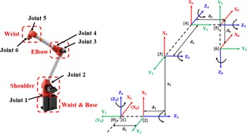
The structure of the robot manipulator investigated herein is the HSR-BR606 developed by Huashu Robot Co., Ltd. and Foshan Institute of Intelligent Equipment Technology. The specific structure and the corresponding coordinate frames based on the modified Denavit-Hartenberg model [Reference Siciliano and Khatib25] are illustrated in Fig. 3. The offset structure allows the robot to work in a narrow space constraint such as factory for intensive stamping and inside the machining center. In order to be more intuitive, the three views and axonometric drawing of the robot are shown in Fig. 4.
Structure and coordinate frames of the HSR-BR606 robot manipulator.

As discussed in Section 1, it is difficult to find a closed-form solution of the IK for such kind of robot manipulator. To obtain the numerical solutions of the IK, it is necessary to search a reasonable initial estimation of the joint configuration. Heuristic techniques may be suitable to deal with the estimation, but implementation of the real-time control is not satisfactory due to the large amount of computation for each estimation. According to the coordinate frames shown in Fig. 3, it can be easily simplified into an Euler wrist structure by translating the frames {5} and {6} at a distance of
 $ - {d_5}$
along the Y axis of the frame {4}. It can be seen in Fig. 5 that the Z axes (joint axes) of the frame {4}{5}{6} intersect at a common point called virtual wrist center [Reference Wu, Yang, Miao, Xie and Chen26] after translation. The position and orientation of the center can be decoupled and thus the analytical solution of the IK can be obtained in this case.
2.2. Forward kinematics
The end pose in Cartesian coordinate can be mapped from the known robot manipulator configuration by the FK. In the IK solution method, the FK is used to identify the current pose according to the estimated joint variables. Kinematics structure of the robotic manipulators in this paper is described by the modified DH (MDH) convention, and the parameters with respect to the coordinate frames of the HSR-BR606 in Figs. 3 and 5 are illustrated in Table I. The specific values of parameter inside are d
2 = 96, a
2 = 726, d
3 = 126.5, d
4 = 630.5, d
5 = 91, d
6 = 122, where α
i-1
, a
i-1
, and d
i
are structure parameters. α
i-1
and a
i-1
, respectively, are the rotation and translation between Z
i
and Z
i-1
about the X
i-1
axis. d
i
is the distance from the X
i-1
axis the X
i
axis along the Z
i
axis. The structure parameters are known and the joint variables
 $\theta$
i
(i=1, 2, 3, 4, 5, 6) vary with the motion. Table II shows the rotation limits of each joint, and the constraints will be considered in the simulation that the group of angles are selected within the ranges.
The MDH parameters of the HSR-BR606.

The three views and axonometric drawing of the robot manipulator.

The changes in wrist structure before and after simplification.

Joint ranges of the HSR-BR606.

According to the MDH convention, the homogeneous matrix transforming link coordinate frame {i} with respect to frame {i-1} is expressed as [Reference Craig2]
 \begin{align}{}_i^{i - 1}T( {{\theta _i}} ) = Ro{t_X}( {{\alpha _{i - 1}}} )Tran{s_X}( {{a_{i - 1}}} )Ro{t_Z}( {{\theta _i}} )Tran{s_Z}( {{d_i}} )\nonumber\\ = \left[ {\begin{array}{c@{\quad}c@{\quad}c@{\quad}c}{{\rm{cos}}{\theta _i}}&{ - {\rm{sin}}{\theta _i}}&0&{{a_{i - 1}}}\\ \\[-7pt] {{\rm{sin}}{\theta _i}{\rm{cos}}{\alpha _{i - 1}}}&{{\rm{cos}}{\theta _i}{\rm{cos}}{\alpha _{i - 1}}}&{ - {\rm{sin}}{\alpha _{i - 1}}}&{ - {\rm{sin}}{\alpha _{i - 1}}{d_i}}\\ \\[-7pt] {{\rm{si}}n{\theta _i}{\rm{sin}}{\alpha _{i - 1}}}&{{\rm{cos}}{\theta _i}{\rm{sin}}{\alpha _{i - 1}}}&{{\rm{cos}}{\alpha _{i - 1}}}&{{\rm{cos}}{\alpha _{i - 1}}{d_i}}\\ \\[-7pt] 0&0&0&1\end{array}} \right]{\rm{\;\;}}\end{align}
The end pose homogeneous matrix of robot in the base coordinates can be expressed as
 \begin{align}{}_6^0T = {}_1^0T\left( {{\theta _1}} \right){}_2^1T\left( {{\theta _2}} \right){}_3^2T\left( {{\theta _3}} \right){}_4^3T\left( {{\theta _4}} \right){}_5^4T\left( {{\theta _5}} \right){}_6^5T\left( {{\theta _6}} \right) = \left[ {\begin{array}{c@{\quad}c}R&P\\ 0&1\end{array}} \right]\end{align}
where
 $\;R$
represents a 3×3 rotation matrix and
 $P$
is a 3×1 position vector of transformation matrix
 ${}_6^0T$
.
2.3. Inverse kinematics
In the proposed method, the IK involves solution of the simplified wrist structure and the actual offset wrist structure.
2.3.1. IK solution for simplified structure
The 6-DOF robot manipulator with simplified structure that satisfies the Pieper criterion can be obtained, when d 5 = 0. In this case, the end position of simplified mechanism is still not exactly the position of virtual wrist center. It can be seen in Fig. 5 that there is a position translation (d 6, along the Z of {6}) between them. The pose of the virtual wrist center is obtained by using the pose of the end coordinate frame ([X Y Z A B C]). Assuming the pose matrix of frame {6} is as following:
 \begin{align}{}_6^0T = Ro{t_z}( A )Ro{t_Y}( B )Ro{t_X}( C )Tran{s}( {X,Y,Z} ) = \left[ {\begin{array}{c@{\quad}c@{\quad}c@{\quad}c}n&o&a&P\end{array}} \right] = \left[ {\begin{array}{*{20}{c}}{{n_x}}&{{o_x}}&{{a_x}}&X \\ \\[-7pt] {{n_y}}&{{o_y}}&{{a_y}}&Y\\ \\[-7pt] {{n_z}}&{{o_z}}&{{a_z}}&Z\\ \\[-7pt] 0&0&0&1\end{array}} \right]\end{align}
where
 $n\;$
= [
 ${n_x}$
 ${n_y}$
 ${n_z}$
]
T
,
 $o$
= [
 ${o_x}$
 ${o_y}$
 ${o_z}$
]
T
and
 $a$
= [
 ${a_x}$
 ${a_y}$
 ${a_z}$
]
T
are called normal vector, sliding vector, and approaching vector.
Then translating the origin of the frame {6} to the virtual wrist center the pose matrix is expressed as
 \begin{align} &\quad Ro{t_z}( A )Ro{t_Y}( B )Ro{t_X}( C )Tran{s}( {X,Y,Z} )Tran{s}( {0,\;0,\; - {d_6}} ) \nonumber\\[3pt] &= \left[ {\begin{array}{c@{\quad}c@{\quad}c@{\quad}c}{{n_x}}&{{o_x}}&{{a_x}}&X\\ \\[-7pt] {{n_y}}&{{o_y}}&{{a_y}}&Y\\ \\[-7pt] {{n_z}}&{{o_z}}&{{a_z}}&Z\\ \\[-7pt] 0&0&0&1\end{array}} \right]\left[ {\begin{array}{c@{\quad}c@{\quad}c@{\quad}c}1&0&0&0\\ \\[-7pt] 0&1&0&0\\ \\[-7pt] 0&0&1&{ - {d_6}}\\ \\[-7pt] 0&0&0&1\end{array}} \right] = \left[ {\begin{array}{c@{\quad}c@{\quad}c@{\quad}c}{{n_x}}&{{o_x}}&{{a_x}}&{X - {a_x}{d_6}}\\ \\[-7pt] {{n_y}}&{{o_y}}&{{a_y}}&{Y - {a_y}{d_6}}\\ \\[-7pt] {{n_z}}&{_z}&{{a_z}}&{Z - {a_z}{d_6}}\\ \\[-7pt] 0&0&0&1\end{array}} \right]\;\;\;\;\;\;\;\;\;\;\end{align}
The position of virtual wrist center is determined by the former three joints, and it can be obtained from Eqs. (1)–(3):
 \begin{align}{}^0{P_{4org}} = {}_1^0T\left( {{\theta _1}} \right){}_2^1T\left( {{\theta _2}} \right){}_3^2T\left( {{\theta _3}} \right){}^3{P_{4org}} = \left[ {\begin{array}{*{20}{c}}{{X} - {a_x}{d_6}}\\ \\[-7pt] {{Y} - {a_y}{d_6}}\\ \\[-7pt] {{Z} - {a_z}{d_6}}\\ \\[-7pt] 1\end{array}} \right]\end{align}
where
 ${}^0{P_{4org}}$
and
 ${}^3{P_{4org}}$
are position vectors of transformation matrices
 ${}_4^0T$
and
 ${}_4^3T$
, respectively:
 \begin{align}\left[ {\begin{array}{*{20}{c}}{{X} - {a_x}{d_6}}\\ \\[-7pt] {{Y} - {a_y}{d_6}}\\ \\[-7pt] {{Z} - {a_z}{d_6}}\end{array}} \right] = \left[ {\begin{array}{*{20}{c}}{({d_4}{s_{23}} + {a_2}{c_2}){c_1} + ({d_2} + {d_3}){s_1}}\\\\[-7pt] {({d_4}{s_{23}} + {a_2}{c_2}){s_1} + ({d_2} + {d_3}){c_1}}\\ \\[-7pt] {{a_2}{s_2} - {d_4}{c_{23}}}\end{array}} \right]\end{align}
where
 ${s_i} = {\rm{sin}}{\theta _i},{\rm{\;}}{c_i} = {\rm{cos}}{\theta _i}$
,
 ${\rm{\;}}{s_{ij}} = {\rm{sin}}\left( {{\theta _i} + {\theta _j}} \right)$
,
 ${c_{ij}} = {\rm{cos}}\left( {{\theta _i} + {\theta _j}} \right)$
.
The former three joint variables (
 $\theta$
1,
 $\theta$
2,
 $\theta$
3) can be obtained from Eq. (6). The last three joints variables (
 $\theta$
4,
 $\theta$
5,
 $\theta$
6) only affect the orientation of the end. The difference between the orientation of coordinate frame {3} and coordinate frame {6} depends on the last three joints (
 $\theta$
4,
 $\theta$
5,
 $\theta$
6).
 \begin{align}{}_6^3R = {}_3^0{R^{ - 1}}{}_6^0R = \left[ {\begin{array}{c@{\quad}c@{\quad}c}{{c_4}{c_5}{c_6} - {s_4}{s_6}}&{ - {c_6}{s_4} - {c_5}{s_6}}&{{c_4}{s_5}}\\ \\[-7pt] {{c_6}{s_5}}&{ - {s_5}{s_6}}&{ - {c_5}}\\ \\[-7pt] {{c_4}{s_6} + {c_5}{c_6}{s_4}}&{{c_4}{c_6} - {c_5}{s_4}{s_6}}&{{s_4}{s_5}}\end{array}} \right]\end{align}
where
 ${}_m^nR$
is the rotation matrix of {m} with respect to {n}.
If
 ${}_6^3R\left( {2,{\rm{\;}}3} \right) \ne \pm 1$
, the last three joint variables
 $\theta$
4,
 $\theta$
5, and
 $\theta$
6 can be obtained by Eq. (7), and the analytical solution is as following:
 \begin{align}{\theta _5} &= {\rm{acos}}\left( { - {}_6^3R\left( {2,\;3} \right)} \right)\nonumber\\[3pt] {\theta _4} &= {\rm{atan}}2\left( {\frac{{{}_6^3R\left( {3,\;3} \right)}}{{{s_5}}},\;\frac{{{}_6^3R\left( {1,\;3} \right)}}{{{s_5}}}} \right) \nonumber\\[3pt] {\theta _6} &= {\rm{atan}}2\left( {\frac{{ - {}_6^3R\left( {2,\;2} \right)}}{{{s_5}}},\;\frac{{{}_6^3R\left( {2,1} \right)}}{{{s_5}}}} \right)\end{align}
2.3.2. IK solution for actual structure
Assuming the desired pose matrix (
 ${}_6^0{T_d}$
) of the coordinate frame {6} of the robot manipulator with offset wrist is given as following:
 \begin{align}{}_6^0{T_d} = \left[ {\begin{array}{c@{\quad}c@{\quad}c@{\quad}c}{{n_{xd}}}&{{o_{xd}}}&{{a_{xd}}}&{{X_d}}\\ \\[-7pt] {{n_{yd}}}&{{o_{yd}}}&{{a_{yd}}}&{{Y_d}}\\ \\[-7pt] {{n_{zd}}}&{{o_{zd}}}&{{a_{zd}}}&{{Z_d}}\\ \\[-7pt] 0&0&0&1\end{array}} \right]\end{align}
The pose matrix of the coordinate system {6} of the simplified structure can be obtained by translating the desired pose matrix along the Y axis of the coordinate frame {6} of actual structure in negative direction of the d 5.
 \begin{align}{}_6^0{T_d}Tran{s}\left( {0,\; - {d_5},\;0} \right) &= \left[ {\begin{array}{c@{\quad}c@{\quad}c@{\quad}c}{{n_{xd}}}&{{o_{xd}}}&{{a_{xd}}}&{{X_d}} \\ {{n_{yd}}}&{{o_{yd}}}&{{a_{yd}}}&{{Y_d}}\\ {{n_{zd}}}&{{o_{zd}}}&{{a_{zd}}}&{{Z_d}}\\ 0&0&0&1\end{array}} \right]\left[ {\begin{array}{c@{\quad}c@{\quad}c@{\quad}c}1&0&0&0\\ 0&1&0&{ - {d_5}}\\ 0&0&1&0\\ 0&0&0&1\end{array}} \right]\nonumber \\ &= \left[ {\begin{array}{c@{\quad}c@{\quad}c@{\quad}c}{{n_{xd}}}&{{o_{xd}}}&{{a_{xd}}}&{{X_d} - {o_{xd}}{d_5}}\\ {{n_{yd}}}&{{o_{yd}}}&{{a_{yd}}}&{{Y_d} - {o_{yd}}{d_5}}\\ {{n_{zd}}}&{{o_{zd}}}&{{a_{zd}}}&{{Z_d} - {o_{zd}}{d_5}}\\ 0&0&0&1\end{array}} \right] \end{align}
The pose of coordinate frame {6} in Eq. (10) is equivalent to the end pose of the simplified structure in Section 2.3.1. The joint variables
 ${{\boldsymbol{\theta }}_{\textbf{s}}}$
= [
 ${\theta _{s1}}$
 ${\theta _{s2}}$
 ${\theta _3}$
 ${\theta _{s4}}$
 ${\theta _{s5}}$
 ${\theta _{s6}}$
] of the robot manipulator with no offset wrist (i.e., simplified structure) can be obtained analytically by Eqs. (6) and (8). The joint variables are the approximate solutions of the IK for the robot manipulator with an offset wrist (i.e., actual structure). The joint variables
 ${{\boldsymbol{\theta }}_{\textbf{s}}}$
are then used in the iteration process. The approximate pose
 ${}_6^0{T_s}$
of the actual structure can be obtained by substituting the
 ${{\boldsymbol{\theta }}_{\textbf{s}}}$
into the FK and the homogeneous matrix is as following:
 \begin{align}{}_6^0{T_s} = {}_1^0T\left( {{\theta _{s1}}} \right){}_2^1T\left( {{\theta _{s2}}} \right){}_3^2T\left( {{\theta _{s3}}} \right){}_4^3T\left( {{\theta _{s4}}} \right){}_5^4T\left( {{\theta _{s5}}} \right){}_6^5T\left( {{\theta _{s6}}} \right)\;\;\;\;\;\;\;\;\;\;\;\;\;\;\;\;\;\end{align}
The synthetical error between the approximate pose and the desired pose can be defined as
 \begin{align}e = \|d{P}\|_{2} + \|dAn{g}\|_{2}\end{align}
where
 $\;dP$
is an incremental displacement and
 $dAng$
is an incremental rotation.
 \begin{align}dP = \left[ {\begin{array}{*{20}{c}}{{}_6^0{T_d}\left( {1,\;4} \right) - {}_6^0{T_s}\left( {1,\;4} \right)}\\ \\[-7pt] {{}_6^0{T_d}\left( {2,\;4} \right) - {}_6^0{T_s}\left( {2,\;4} \right)}\\ \\[-7pt] {{}_6^0{T_d}\left( {3,\;4} \right) - {}_6^0{T_s}\left( {3,\;4} \right)}\end{array}} \right]\end{align}
In term of the rotation increment between the approximate pose and the desired pose, the equivalent angle-axis representation is adopted. Based on the Rodrigues’ rotation formula, the equivalent rotation matrix is [Reference Craig2]
 \begin{align}R\left( {K,\varphi } \right) &= {}_6^0{T_s}{\left( {1:3,{\rm{\;}}1:3} \right)^{ - 1}}{}_6^0{T_d}\left( {1:3,{\rm{\;}}1:3} \right)\nonumber\\[3pt] &= \left[ {\begin{array}{c@{\quad}c@{\quad}c@{\quad}c}{{k_x}{k_x}\nu + {\rm{cos}}\varphi }&{{k_x}{k_y}\nu - {k_z}{\rm{sin}}\varphi }&{{k_x}{k_z}\nu + {k_y}{\rm{sin}}\varphi }\\ \\[-7pt] {{k_x}{k_y}\nu + {k_z}{\rm{sin}}\varphi }&{{k_y}{k_y}\nu + {\rm{cos}}\varphi }&{{k_y}{k_z}\nu - {k_x}{\rm{sin}}\varphi }\\ \\[-7pt] {{k_x}{k_z}\nu - {k_y}{\rm{sin}}\varphi }&{{k_y}{k_z}\nu + {k_x}{\rm{sin}}\varphi }&{{k_z}{k_z}\nu + {\rm{cos}}\varphi }\end{array}} \right]=\left[ {\begin{array}{c@{\quad}c@{\quad}c}{{r_{11}}^{\rm{\;}}}&{{r_{12}}^{\rm{\;}}}&{{r_{13}}^{\rm{\;}}}\\ \\[-7pt] {{r_{21}}^{\rm{\;}}}&{{r_{22}}^{\rm{\;}}}&{{r_{23}}^{\rm{\;}}}\\ \\[-7pt] {{r_{31}}^{\rm{\;}}}&{{r_{32}}^{\rm{\;}}}&{{r_{33}}^{\rm{\;}}}\end{array}} \right]\end{align}
where
 $\nu = 1 - {\rm{cos}}\varphi $
, and
 $K$
= [
 ${k_x},\;{k_y},\;{k_z}$
] is a unit vector passing through the origin of the coordinate system {6} of the robot manipulator with offset wrist.
 $\varphi $
is the angle of rotation around the
 $K$
vector. The desired orientation will be achieved after rotating the approximate orientation about
 $K$
vector by the angle
 $\varphi $
.
The vector
 $K$
and the angle
 $\varphi $
can be solved from the given rotation matrix [Reference Bottema and Roth27]:
 \begin{align}\varphi = {\rm{arccos}}\left( {\frac{{{r_{11}} + {r_{22}} + {r_{33}} - 1}}{2}} \right)\end{align}
 \begin{align}K = \left[ {\begin{array}{c}{{k_x}}\\ \\[-7pt] {{k_y}}\\ \\[-7pt] {{k_z}}\end{array}} \right] = \frac{1}{{2{\rm{sin}}\varphi }}\left[ {\begin{array}{*{20}{c}}{{r_{32}} - {r_{23}}}\\ \\[-7pt] {{r_{13}} - {r_{31}}}\\ \\[-7pt] {{r_{21}} - {r_{12}}}\end{array}} \right]\end{align}
Thus, the incremental rotation
 $dAng$
is expressed as
 \begin{align}dAng = {}_6^0{T_s}\left( {1:3,1:3} \right)K\varphi \end{align}
Combining the position increment
 $dP$
and rotation increment
 $dAng$
into a vector
 $dX$
= [
 $dP$
 $dAng$
]
T
expressed in world coordinate, the
 $dX$
is the differential motion (6x1) corresponding to the infinitesimal motion from approximate pose to desired pose.
If the synthetical error
 $e$
is within the reasonable tolerance, the iteration will be ceased and the numerical IK solution of the robot manipulator with offset wrist can be obtained. Otherwise, new possible joint variables for next iteration will be generated based on the differential variables of the joint configuration
 $d\theta $
, which is calculated by the Jacobian matrix and the differential motion
 $dX$
.
 \begin{align}d\theta = {J^{ - 1}}dX\end{align}
The Jacobian matrix of the actual structure with offset wrist is expressed as following:
 \begin{align}{\rm{J}} = \left[ {\begin{array}{c@{\quad}c@{\quad}c}{{J_{pi}}}& \cdots &{{J_{pn}}}\\ \\[-7pt] \vdots & \ddots & \vdots \\ \\[-7pt] {{J_{Oi}}}& \cdots &{{J_{On}}}\end{array}} \right] \left[ {\begin{array}{c}{{J_{pi}}}\\ \\[-7pt] {{J_{Oi}}}\end{array}} \right] = \left[ {\begin{array}{*{20}{c}}{{}_{\rm{\;}}^0{Z_i}\left( {{}_{\rm{\;}}^0{P_n} - {}_{\rm{\;}}^0{P_i}} \right)}\\ \\[-7pt] {{}_{\rm{\;}}^0{Z_i}}\end{array}} \right]{\rm{\;i}}=1,2,3, \cdots ,6,{\rm{\;}}n=6\end{align}
where
 ${}^0{Z_i}$
is the vector representation of the Z axis of in the coordinate frame {i} with respect to the base coordinate frame {0}.
 ${}^0{P_i}$
is the vector representation of the origin of the coordinate frame {i} with respect to the base coordinate frame {0}.
The new possible joint variables
 $\theta $
can be obtained by Eq. (20). Substituting the new joint variables into Eq. (2), the current pose of the robot manipulator with offset wrist can be obtained and the synthetical error between the current pose and the desired pose will be calculated to decide whether the joint variables need to refresh again or not.
 \begin{align}\theta = \theta + d\theta \end{align}
2.4. Inverse kinematics algorithm flow
The key steps for the proposed IK algorithm are as followed:
-
(1) Translating the frame {6} of 6-DOF robot manipulator with offset wrist in its Y axis by d5 to obtain the pose of frame{6} of 6-DOF robot with no offset wrist. The joint variables of simplified structure can be obtained by Eqs. (3)–(8);
-
(2) Using the joint variables of simplified structure as the input of Eq. (2) to get the pose matrix of the frame {6} of 6-DOF robot manipulator with offset wrist.
-
(3) Calculating the position increment
 $dP$
and rotation increment
$dAng$
by Eqs. (13)–(17) and obtaining the synthetical errors
$e$
by Eq. (12).
-
(4) Judging whether the synthetical error
$e$
is within the pre-set criteria or not. If the synthetical error is within the reasonable error range, the iteration is stopped and a current value of the joint variables as the iterative numerical solution of the IK of the 6-DOF robot manipulator with offset wrist is returned. If the synthetical error is out of range, the
$d\theta $
is calculated by the Jacobian matrix of the 6-DOF robot manipulator with offset wrist and then get new joint variables for next iteration. -
(5) Repeating step (2)-step (4) until the synthetical error is within the pre-set criteria or the number of iteration reaches the maximum setting number.


The generalized pseudocode description is as following:
The pseudocode of algorithm

3. Simulations and discussion
In this section, the proposed algorithm is tested and discussed in terms of accuracy, efficiency and application for motion planning. To ensure the reproducibility of experiments and consistency, the model of the robot manipulator to implement the validation of the algorithm is the same as mentioned above, and the structure parameters are summarized in Section 2.2. After evaluating the performance of the proposed algorithm, a comparative experiment is conducted between the algorithm and the improved Jacobian transpose (IJT) algorithm developed by Corke et al. [Reference Corke28] The programming and experiments are developed and carried out on a CPU of Intel Core i5-7400 3.00 GHz with 16 GB RAM in MATLAB 2019b software.
3.1. Accuracy and efficiency
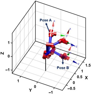
In order to investigate the accuracy and efficiency for the proposed algorithm, the first experimental scheme is that the joint coordinates vary from Pose A (20° 90° 30° 10° –90° 0°) to Pose B (–80° 50° 15° –80° 0° 10°) as illustrated in Fig. 6, and 1000 sets of joint angles between Poses A and B are interpolated by a quintic (5th order) polynomial in joint space. After interpolation, the corresponding homogeneous matrices can be obtained by FK, and the joint variables are solved via the proposed IK algorithm.
The poses of the robot manipulator in the simulation. Starting from Pose A (20° 90° 30° 10° –90° 0°) to end Pose B (–80° 50° 15° –80° 0° 10°).

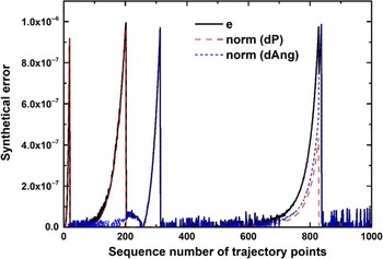
The distribution of the error during convergence can be seen in Fig. 7 where the convergence criteria is set to 1×10⁻⁶ in this test. The synthetical error (
 $e$
) includes position error (dP) and orientation error (dAng) as mentioned in Eq. (12). In other word, the synthetical error can be considered as a spatial displacement contributed by the incremental displacement and incremental rotation. Figure 7 shows that the synthetic errors of 1000 test poses are within a reasonable range and most of the errors are much lower than the convergence criteria. For the first two hundred groups of poses, the synthetical errors are mainly dominated by the position error. In sequence number of trajectory points from 200 to 323, the orientation errors are dominant, and the peak of norm (dAng) reaches 9.698×10⁻⁷. For the points from 700 to 850, the contribution of position error and orientation error is relatively obvious, and the orientation component is slightly larger than the position component. The average synthetical error is 1.09×10⁻⁷, and its standard deviation is 2.07×10⁻⁷.
The distribution of the error and its components during convergence.

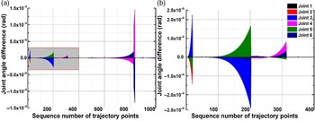
Figure 8 shows the differences between the joint angles solved by the algorithm and the interpolated joint angles. It can be seen in Fig. 8(a) that large differences appear in trajectory points of sequence number around 830 at about Joint 4 and Joint 6, which have a greater influence on the orientation error of the robot. Figure 8(b) is the enlargement of the gray region (points 1–400) in Fig. 8(a). The differences of all joint angles are within ±3×10⁻⁶ rad. The peaks in Fig. 7 can be explained by the accumulation of the angle difference of each joint in Fig. 8. In other words, Fig. 8 shows the detailed information of the synthetical errors in terms of the difference between calculation angle and target angle of each joint. Usually, the first three joints cooperate to determine the end position, and the last three joints determine the orientation. Because of the offset structure, the rotation of Joint 5 affects both the position and orientation of the end frame. For instance, the peaks of Joint 3 and Joint 5 of sequence number 200 in Fig. 8(b) result in the peak of synthetical error of the same sequence number in Fig. 7. The mean, standard deviation, maximum, and minimum of differences for each joint are listed in detail in Table III.
Statistical analysis of differences of the IK solution for each joint.

The differences between the joint angles solved by algorithm and the interpolated joint angles.

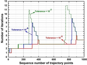
The number of iterations for different tolerance.

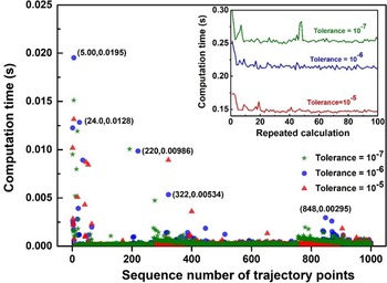
To investigate the computational efficiency, the number of iterations, and computation time are also considered in the same experiment. As shown in Fig. 9, when the convergence accuracy (i.e., tolerance) is set to 1×10⁻⁷, 1×10⁻⁶, and 1×10⁻⁵, the maximum number of iterations is 12, 9, and 5, respectively. Figure 10 shows the calculation time of the algorithm in terms of a single joint configuration and the joint configurations from pose A to pose B. It turns out that the calculation time is unstable at the beginning and the maximum time consumption of the algorithm is 0.0195 s in test 5 for tolerance of 1×10⁻⁶. The content of the brackets next to some points refer to the specific computation time for blue circle points in corresponding test number, which is used as a reference for neighboring points. For calculation of a single joint configuration, the mean time is 0.393, 0.346, and 0.263 ms for tolerance of 1×10⁻⁷, 1×10⁻⁶, and 1×10⁻⁵. An inset graph in the upper right corner illustrates the computation time for the 100 repeated calculations of the 1000 joint configurations for different tolerance. It can be seen in Fig. 10 that the IK solutions from pose A to pose B take up to 0.3, 0.25, and 0.18 s for tolerance of 1×10⁻⁷, 1×10⁻⁶, and 1×10⁻⁵, respectively. The mean time consuming is 0.255, 0.149, and 0.215 s.
The computation time of single joint configuration for different tolerance and the computation time of 1000 joint configurations for different tolerance (inset graph).

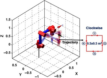
The motion trajectory for rectangular path.

3.2. Motion planning
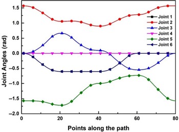
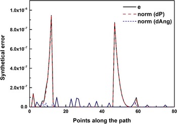
In this section, the performance of algorithm to track a trajectory planed in Cartesian coordinate is discussed. The trajectory is a rectangle and the motion of the end of robot manipulator starts and ends with the initial pose (0° 90° 0° 0° –90° 0°) as illustrated in Fig. 11. The rectangle with 0.5 m sides totally consists of 80 points described by homogeneous matrices and each side has 20 points. In the simulation, the end moves clockwise along the sides and the convergence accuracy is set to 1×10⁻⁶. Figure 12 shows six joint trajectories changing with the points of rectangular path. The trajectories are continuous and smooth. The synthetical error and its components during the convergence can be seen in Fig. 13. Overall, the synthetical errors are much smaller than the convergence criterion except the two peaks caused by the position errors. The orientation errors are below 1×10⁻⁷.
The joint trajectories for the rectangular path.

The distribution of the error along the path.

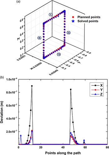
To be more intuitive, Fig. 14(a) shows the actual tracking of the rectangular path. Red circle points are the planned points, and blue star shaped points are the points solved by the proposed method. The motion planning sequence in Fig. 14(a) is marked by 1, 2, 3, and 4 corresponding to the Fig. 11. In general, the proposed algorithm can track all planned points within a synthetical error of 1×10⁻⁶ as mentioned above. Figure 14(b) specifically illustrates the deviation of each axis (X-Y-Z axis of Cartesian coordinates) between actual tracking points and planned points, where the large errors, respectively, appear in point 12 and point 47 in x-axis direction in sequences 1 and 4, and the corresponding deviations are 8.989×10⁻⁷ and 8.452×10⁻⁷ m. The peaks in Fig. 13 correspond to the large errors in Fig. 14. The deviation in Fig. 14(b) shows that the position error peaks of Fig. 13 is mainly caused by the errors in the x-axis direction.
Actual tracking of the rectangular path. (a) The comparison between the actual trajectory and the planned trajectory. (b) The deviation of each axis between actual track and planned track.

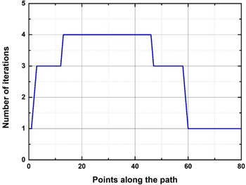
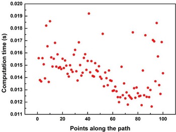
For efficiency, the number of iterations and computation time are investigated as well. Figure 15 shows that the maximum number of iterations is 4, which is less than the first experimental scheme discussed in Section 3.1 because of the relatively simple trajectory in the Cartesian space. Figure 16 shows the computation time for motion planning of a rectangular. To obtain a reasonable estimation, the calculation is repeatedly implemented for 100 times. The range of the calculation time is between 11 and 20 ms, and the mean and standard deviation are 14.43 and 1.66 ms, which satisfy the real-time control for the robot manipulator.
The number of iterations for motion planning of a rectangular.

The computation time for motion planning of a rectangular (a hundred repetitions of calculations).

3.3. Comparing with the IJT algorithm
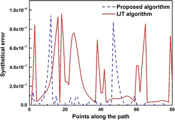
To valid the effectiveness of the proposed algorithm, a general numerical approach (IJT algorithm) for the IK from ref. [Reference Corke28] is used as a reference. The IJT algorithm is developed based on the Jacobian transpose and the Levenberg–Marquardt optimization algorithm which are suitable for any manipulator configuration. The comparison scheme is that both methods are used to solve the IK of the rectangular trajectory illustrating in Fig. 11. The initial estimation of the joint variables of the IJT algorithm is the joint variables of the previous pose, which aims to speed up the convergence. Figure 17 shows the distribution of the synthetical errors by using the IJT algorithm to track the rectangular path. Compared to the proposed algorithm, the IJT algorithm has more peaks, which indicates a relatively lower accuracy. Specifically, Table IV shows the statistical analysis of the synthetical errors of the two methods. It can be seen that the accuracy of the algorithm proposed in the paper is three times higher than that of the IJT algorithm.
Statistical analysis of synthetical errors for the proposed and IJT algorithm.

The distribution of synthetical errors of the proposed and IJT algorithm.

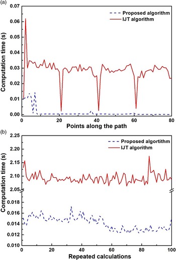
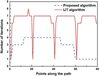
Figure 18 shows the comparison of the calculation time regarding to a single point and a complete rectangular path for the two algorithms. It can be seen in Fig. 18(a) that there are 4 valleys corresponding to points 1, 21, 41, and 61 for the IJT algorithm. The pose of point 1 is the same as the initial pose, while points 21, 41, and 61 are the same corner points as the previous poses (i.e., the poses of points 20, 40, and 60). For calculating the IK of a complete rectangular path (a total of 80 points), the calculation time of the IJT algorithm fluctuates between 2.075 and 2.175 s, while the proposed algorithm is between 0.013 and 0.018 s. The statistical analysis of the calculation time of the two algorithms is shown in Table V. Figure 19 shows the number of iterations of the two algorithms for each planning point. The valleys here are corresponding to the valleys as shown in Fig. 18(a), and the reason of the formation is the same as mentioned above. The maximum number of iterations of the IJT algorithm is 8 and the algorithm proposed is only half of it. Note that the number of iterations for the proposed algorithm is independent to the previous pose, and it depends on the pose of the simplified structure of the robot manipulator.
Statistical analysis of computation time for the proposed and IJT algorithm.

The computation time of two algorithms (a) The computation time for each single point. (b) The computation time for motion planning of a rectangular (a hundred repetitions of calculations).

The number of iterations for the two algorithms to track the same rectangular trajectory.

4. Conclusion
This paper presents an improved IK solution for the 6-DOF robot manipulator with an offset wrist. By translating certain coordinate frames depending on the structure of the robot manipulator, the analytical solution of the simplified reconstructed structure is presented for the IK. This solution is served as an approximate solution for the actual offset structure, and the exact solution satisfying the convergence accuracy can be obtained by iteration. Further, a robot manipulator HSR-BR606 with an offset wrist is used as an example to specifically elaborate the mathematical procedure of the algorithm and to carry out the simulation calculation of the algorithm. Simulation experiments are carried out to investigate the performance of the algorithm in terms of accuracy, efficiency, and motion planning. A comparative experiment with the IJT algorithm is also conducted. The results show that the proposed algorithm has the advantages of high accuracy with short calculation time compared to the IJT algorithm. The proposed method is simple and efficient, which facilitates the real-time performance and as well as reduces the computational burden. It is believed that this method can be extended to other kinds of robot manipulators with offset structures.
Acknowledgments
The authors disclosed receipt of the following financial support for the research, authorship, and/or publication of this article: The authors acknowledge the financial support provided by the Key Project of Foshan Kernel Technology (Project No. 1920001001367) and the Science and Technology Project of Guangdong Province (Project No. 2019B090919001).