I. INTRODUCTION
Direct chill (DC) casting is a common process for industrial production of aluminum alloy billets and slabs. Just due to its importance for fabricating semifinished products, numerous studies have been carried out to develop this technique. Usually, DC casting process has two forms—vertical DC (VDC) and horizontal DC (HDC). Reference Zhao, Cui, Dong, Wang and Zhang1 Despite that VDC casting is the most preferred process used in industry at present, HDC process is attracting attention of aluminum industry in recent years. Reference Dawood2 Compared to VDC, HDC has advantages of lower investment cost, higher flexibility, longer casting times, etc. Reference Wertli3 Therefore, it is of practical significance to further develop HDC process.
To improve the qualities of slabs and billets, many techniques referring to application of electromagnetic field (EMF) to the DC casting processes have been developed, such as electromagnetic casting (EMC), Reference Vivès and Ricou4,Reference Meyer, Szekely, Elkaddah, Vivès and Ricou5 casting, refining, electromagnetic (CREM), Reference Vivès6,Reference Vivès7 and low frequency electromagnetic casting (LFEC). Reference Zhao, Cui, Dong and Zhang8–Reference Zuo, Nagaumi and Cui11 The EMC mainly aimed at improving surface quality of the ingots, whereas the CREM aimed at both surface quality and microstructure. For the LFEC, besides these advantages, it could also reduce macrosegregation and avoid hot tearing of large sized ingots. In these techniques, the EMF was usually applied individually. In reality, experiments of combining the same or different EMFs and thus imposed to the DC casting processes were also conducted. A typical example was the electromagnetic vibration technique, in which alternating and direct current EMFs were applied simultaneously to the casting process of aluminum alloys. Reference Vives12 It was found that the microstructures became more homogeneous and refined than those with a single one. Other than this, combined out-phase EMFs were also imposed to the casting process of hollow aluminum alloy ingots. Reference Wang, Cui and Yang13 In this technique, two different alternating coils were designed to possess different phases. The results showed that the properties of the ingots were improved greatly compared to those with an individual EMF. Zhu et al. applied combined EMFs to the HDC casting process of 3004 aluminum alloy ingot. Reference Zhu, Zhao, Zuo, Wang and Cui14 In that experiment, the first half of the ingot was cast without EMFs, whereas the second half was cast under combined EMFs. They showed the macrostructure evolution of the ingot during a switching “off–on” combined EMF process and found that the structure was transformed from columnar to equiaxed grains. However, few microstructural details about this transformation were clarified. A crystallographic characterization of the microstructures was also not carried out. In addition, structural transformation during a switching “on–off” combined EMF process was also not exhibited. These should be of great importance to understand the effect of EMFs on casting process.
In such a context, a 3004 aluminum alloy ingot was produced by a HDC casting process, during which combined EMFs were applied in a switching “on–off” order. The macro- and microstructure transformation induced by combined EMFs was carefully studied with the aid of EBSD technique in this work.
II. EXPERIMENTAL
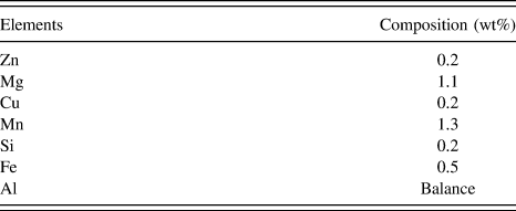
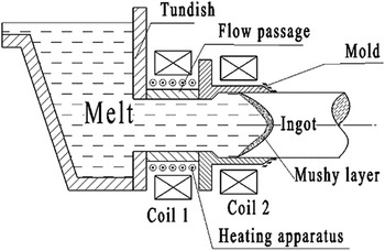
A 3004 aluminum alloy (the nominal chemical composition is shown in Table I) ingot was produced by a HDC casting process. The casting configuration is schematically illustrated in Fig. 1. Reference Zhu, Zhao, Zuo, Wang and Cui14 The equipment mainly consists of tundish, flow passage, heating apparatus, mold with an embedded graphite ring, and induction coils 1 and 2. The two coils surrounding the flow passage and mold were made of 60-turn water-cooled copper tubes. The combined EMFs were applied by inputting 200 A and 50 Hz alternating currents into the two coils simultaneously. Thus, the magnitudes of the ampere turns for both coils are 12,000 ampere-turn.
Chemical composition of 3004 aluminum alloy.

Schematic diagram of the HDC casting configuration.

The 3004 alloy was melted in an induction furnace. When the temperature reached 760 °C, the melt was poured into an electrical resistance furnace, and then degassed, slag-removed and refined. After kept for 20 min at 710 °C, the melt was introduced into the tundish to produce a Φ100 mm ingot at a casting speed of 140 mm/min. During the casting process, combined EMFs were applied for the first half of the slab and then switched off for the second half.
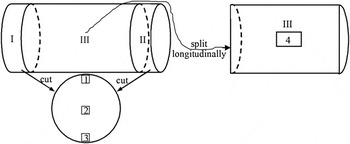
A cylinder of length of about 100 mm containing the EMF transformation region (from switching on to switching off the combined EMFs) was cut from the ingot, as schematically shown in Fig. 2. Two transverse slices (I and II) with a thickness of 10 mm to the casting direction were cut out from the two ends of the cylinder for macrostructure observation. Subsequently, three specimens (1, 2, and 3) were cut out from each slice for microstructure analysis. Then, the remaining cylinder (III) was split longitudinally along the casting direction into two halves for further macrostructure observation. Afterward, the specimen (4) was cut out from the central region of one of the halves for microstructure analysis. The macrostructures were etched with NaOH (25 wt%) reagent after mechanical polishing and taken with an OLMPUS C8080WZ camera, whereas the microstructures were electro-oxidized and then observed using a Leica DMR optical microscope under polarized light. To further characterize the microstructural transformation, the specimen (4) cut out from the central region of one of the halves was also electrolytically polished (100 mL perchloric acid and 800 mL methanol, 25 V, 10 s). Then, EBSD auto scanning was performed in the upper center of the specimen with a step size of 10 μm.
Schematic diagram of the relative positions of the slices and specimens in the cylinder containing the EMF transformation region. The slices (I and II) were cut transversely and the cylinder (III) was split longitudinally for macrostructure observation, whereas the specimens (1, 2, 3, and 4) are taken for microstructure analysis.

III. RESULTS
A. Macro- and microstructures
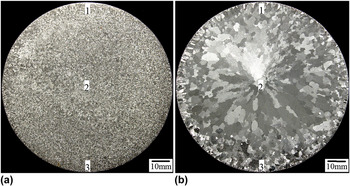
Figures 3(a) and 3(b) show the macrostructures in the two end cross sections of the sliced cylinder with and without combined EMFs, respectively. It can be observed that with the combined EMFs the structure is relatively uniform and mainly shows small equiaxed form [see Fig. 3(a)]. When the EMFs are switched off, the structure becomes inhomogeneous—coarse grains with equiaxed and columnar forms comprise the central part and a thin layer of relatively fine grains is formed at the periphery of the cross section [see Fig. 3(b)].
Macrostructures in the two end cross sections of the sliced cylinder (a) with and (b) without combined EMFs, respectively.

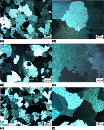
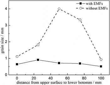
To more clearly show the effects of the combined EMFs, Figs. 4(a)–4(f) display the microstructures corresponding to positions 1, 2, and 3 in Figs. 3(a) and 3(b), respectively. It can be observed that in each case (whether with or without the EMFs) the grains near the bottom surface [Figs. 4(c) and 4(f)] are finer than those near the top surface of the ingot [Figs. 4(a) and 4(d)]. However, the grains in general are coarsened greatly by switching-off the combined EMFs. To further reveal the change of the structures, Fig. 5 shows the average grain size distributions on cross sections of the two slices from the upper surface to lower bottom. As can be seen, the grain size is small and shows a uniform distribution on the whole section with the combined EMFs. When the EMFs are switched off, the grain size is obviously increased and reveals quite inhomogeneous distribution (the size in the central part is much larger than that in the other parts). All of these suggest that the combined EMFs help to refine and uniform the grains effectively.
Microstructures corresponding to positions 1, 2, and 3 in Figs. 3(a) and 3(b), respectively. (a)–(c): without EMFs; (d)–(f): with EMFs.

Average grain size distribution on the cross section of the two slices with and without EMFs from the upper surface to the lower bottom.

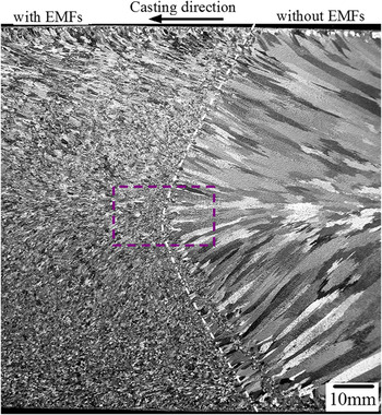
To understand the three-dimensional structure transformation, Fig. 6 shows the macrostructure in the longitudinal section of the sliced cylinder. It can be seen that the structure of the ingot exhibits an obvious transformation from a mixture of equiaxed (mainly in the lower part) and fine columnar (mainly in the upper part) to coarse columnar grains with switching off the EMFs (with the macrostructures in both cross and longitudinal sections of the ingot, it can be determined that the coarse grains with equiaxed and columnar forms in Fig. 3(b) are actually columnar in three-dimensions). The dividing line (dashed and white) between the two structures presents a horizontally lying “V” shape, displaying the solidification interface. Obviously, the principal axes of the coarse columnar grains are in a direction perpendicular to the solidification interface.
Macrostructure in the longitudinal section of the sliced cylinder.

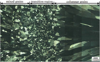
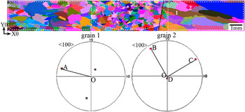
To more clearly reveal this transformation, Fig. 7 shows the microstructure corresponding to the dashed rectangular frame in Fig. 6. In this figure, it is interestingly found that some quite fine equiaxed grains exist in the central part of the specimen, which seem to comprise a transition region between the above-mentioned mixture and coarse columnar grains. To further identify the existence of such transition region, Fig. 8 shows the all-Euler orientation micrograph corresponding to the upper central part of Fig. 7. In the micrograph, different colors represent differently oriented α-Al grains. As can be seen, some fine equiaxed grains are concentrated in the center, which further confirms the presence of the transition region.
Microstructure corresponding to the dashed rectangular frame in Fig. 6.

All-Euler orientation micrograph corresponding to the upper central part of Fig. 7. The images below give two <100> pole figures corresponding to columnar grain 1 and equiaxed grain 2 in the micrograph respectively, which will be discussed in the next section. Axes X0 and Y0 denote the two-dimensional coordinate system in the microstructure observation plane.

B. Crystallography
To better understand the transformation of the microstructures, some crystallographic analyses are also conducted in this work. Firstly, the analysis mainly aims at some individual grains, which can help us to know why they are in an equiaxed or columnar form. In Fig. 8, two <100> pole figures corresponding to columnar grain 1 and equiaxed grain 2 in the all-Euler orientation micrograph are also given. In the pole figure of grain 1, it can be found that the <100> projection line OA is very close to the true <100> crystal line as pole A is close to the outer circle of the pole figure. Reference Li, Zhang, Esling, Zhao, Zuo, Zhang and Cui15,Reference Li, Zhang, Esling, Zhao, Zuo, Zhang and Cui16 Additionally, OA is parallel to the principal axis of grain 1, suggesting that grain 1 grows preferentially along <100>. Furthermore, its preferred growth direction is also perpendicular to the solidification interface, as indicated by the black dotted line in the all-Euler orientation micrograph in Fig. 8. In the pole figure of grain 2, none of the projection lines OB, OC, and OD is perpendicular to the solidification interface, suggesting that no <100> direction of this grain is consistent with the temperature gradient direction. Here, we would like to clarify that some other equiaxed and columnar grains close to grain 1 and grain 2 were also crystallographically analyzed, and similar results were obtained.
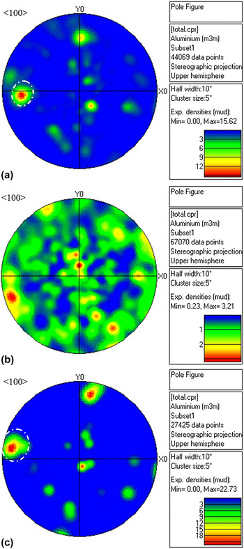
It is known that different microstructures usually correspond to different crystallographic features. Therefore, there should exist crystallographic differences among the three microstructure regions present in the ingot. Based on this, Figs. 9(a)–9(c) show the contoured <100> direction pole figures corresponding to the mixture of equiaxed and fine columnar grains (as enclosed by the dashed white rounded rectangle), fine equiaxed grains (as enclosed by the dashed white circle) and coarse columnar grains (as enclosed by the dashed white rectangle) in Fig. 8, respectively. The images to the right of the pole figures show the multiples of uniform densities (mud) denoted by different colors. In Fig. 9(a), a strong <100> pole with a maximum mud of 15.62 appears in the −X0 direction (as enclosed by the dashed white circle). In Fig. 9(b), there is no strong <100> pole (the maximum mud is only 3.21). In Fig. 9(c), a stronger pole with a maximum mud of 22.73 than that in Fig. 9(a) emerges in the direction close to −X0 (as enclosed by the dashed white circle). All of these suggest that the microstructure transformation is also accompanied by a crystallographic orientation change.
Contoured <100> direction pole figures corresponding to (a) the mixture of equiaxed and fine columnar grains (enclosed by dashed white rounded rectangle), (b) fine equiaxed grains (enclosed by dashed white circle), and (c) coarse columnar grains (enclosed by dashed white rectangle) in Fig. 8, respectively. The images to the right of the pole figures show the multiples of uniform densities (mud) denoted by different colors.

IV. DISCUSSION
A. Macro- and microstructures
Despite that the combined EMFs were applied in a switching “on–off” manner during the HDC casting process of the ingot in this work, we would like to firstly discuss the casting process of the second half of the ingot without the EMFs. Compared to the VDC casting, a typical character of HDC casting is that it is strongly affected by gravity due to the horizontal casting direction. Under the effect of gravity, high-temperature melt rises while low-temperature melt descends in the flow passage and mold, which leads to an inhomogeneous temperature field from the bottom to the top surfaces of the ingot. Reference Zhu, Zhao, Cui, Zuo and Wang17 Furthermore, the contacting pressure between the bottom mold and ingot surface is larger than that between the top mold and ingot surface, which results in a higher cooling intensity of the bottom surface than that of the top surface. Reference Zhu, Zhao, Zuo, Wang and Cui14 Both the low temperature and high cooling intensity at the bottom of the ingot suggest a high melt undercooling and thus a high nucleation rate. Consequently, the grains near the bottom surface [see Fig. 4(f)] are finer than those near the top surface of the ingot [see Fig. 4(d)]. As the melt in the central part is far from the mold and thus has a low undercooling, the grains in this region possess the largest size (see Fig. 5).
Now let's go back to discuss the casting process of the first half of the ingot with the application of combined EMFs. The alternating currents generate two time varying magnetic fields in the melt within the flow passage and mold, respectively, which, in turn, give rise to two induced currents in the melt. Thus, the melt is subjected to electromagnetic body forces caused by the interaction of the induced currents and the magnetic fields. The electromagnetic body force F is the so-called Lorentz force and usually expressed as follows Reference Vivès6 :
 $$F = J \times B = {1 \over \mu }\left( {B\nabla } \right)B-{1 \over {2\mu }}\nabla {B^2}\quad {\rm{,}}$$
where B and J are the magnetic induction intensity and current density generated in the melt, and μ is the permeability of the melt. The first term of the equation is a rotational component which gives rise to a forced convection and flow in the melt, whereas the second term denotes a potential force which is balanced by static pressure of the melt and results in the decrease of contacting pressure between the ingot and mold. Firstly, the forced convection can balance the effects of gravity by mixing the high- and low-temperature melt and thus uniform the temperature field in the melt, which contributes to the homogenization of the microstructures. Secondly, the forced convection accelerates the heat extraction from the melt to the mold and thus reduces the superheat in the melt. Meanwhile, the convection promotes fragmentation of the dendrites at the solidification interface and subsequent crystal multiplication during solidification. Reference Hunt and Jackson18,Reference O’Hara and Tiller19 It is known that when a secondary or higher-order branch of a dendrite initially forms, an increase in the local temperature and/or shearing force due to convection can detach it from the dendrite. Moreover, the crystals nucleated on the flow passage and mold walls may also be sheared off and transported to the solidification interface by the convection. The fragments and the sheared crystals act as potential seeds for the equiaxed grains if the thermal and compositional conditions are appropriate. Both the above-mentioned reduced superheat and potential seeds facilitate to the increase of nucleation rate in the melt. As a consequence, relatively homogeneous structure with small equiaxed grains is formed in the first half of the ingot with the application of the combined EMFs. However, as mentioned previously, some fine columnar grains also exist (see Fig. 6). This is because that the induced Lorentz force is not versatile, which cannot counteract the gravitational effect completely and can also not produce sufficiently enough nucleus to form full equiaxed grains in the structure. Therefore, when referencing the situation without the EMFs, it can be understood that a mixture of equiaxed and fine columnar grains (especially in the upper part of the longitudinal section) is formed in the structure with the application of the EMFs.
As previously mentioned in the results, an interesting transition region composed of fine equiaxed grains is also formed between the mixture and coarse columnar grains. Such a transition region should appear at the moment the EMFs are switched off. According to the analyses above, one thing can be definitely confirmed—these equiaxed grains should mainly originate from the fragments of the dendrites at the solidification interface. When the EMFs are switched on, the forced convection not only produces dendrite fragments but also tends to transport them to the deep melt far from the solidification interface. This means that only some of the fragments can stay in the solidification front to grow into equiaxed or fine columnar grains. However, at the moment the EMFs is switched off, the convection is weakened suddenly. The previously formed fragments barely have time to transfer to other regions. As a result, most of them are held at the solidification front and survive to grow into fine equiaxed grains. When these fragments are depleted, coarse columnar grains are formed under conditions without the EMFs.
B. Crystallography
In the results, it has been shown that columnar grain 1 in Fig. 8 grows preferentially along <100> and its preferred growth direction is also perpendicular to the solidification interface. However, equiaxed grain 2 has no <100> direction consistent with the temperature gradient direction. It is known that dendrite tips grow in most cases along the <100> orientations in metals of cubic crystal structure. Reference Cantor and Vogel20 Therefore, the α-Al grains should grow with the preferred crystallographic direction <100> along the temperature gradient direction, which should be perpendicular to the solidification interface. For grain 1, its initial orientation favors its preferential growth into a columnar crystal as one of its <100> directions is consistent with the temperature gradient direction. In contrast, the initial orientation of grain 2 goes against its preferential growth into a columnar crystal. Thus, it can be concluded that before the equiaxed–columnar transformation the initial orientations of the grains at the solidification interface play a key role in determining whether they can grow into coarse columnar ones.
Moreover, it has also been shown that the three microstructure regions possess different crystallographic features. For the mixture of the equiaxed and fine columnar grains, the relatively strong pole means a preferred <100> orientation in the −X0 direction (i.e., casting direction). This preferred orientation actually arises from the fine columnar grains, the growth of which is still dominantly controlled by the temperature gradient direction despite of the EMFs. As the calculation of the contoured pole figure involves the equiaxed grains, the mud of the relatively strong pole is driven down. For the fine equiaxed grains, the absence of a strong pole implies random orientations. Usually, equiaxed grains are randomly oriented and thus do not show a preferred orientation. For the coarse columnar grains, the strong pole with other linearly distributed poles close to the Y0 direction indicates an intense <100> fiber texture. It has been shown that the internal structure determines that the α-Al columnar grains grow preferentially along <100> direction. Just as aforementioned, the initial orientations of the grains at the solidification interface are important to determine whether they can grow into coarse columnar ones. In other words, the grains with unfavorable initial orientations with respect to the temperature gradient direction are ruled out to grow into columnar grains. Thus, it is natural that the coarse columnar grains reveal a character of intense <100> fiber texture.
V. CONCLUSIONS
A 3004 aluminum alloy ingot was produced by HDC casting process with and without the application of combined EMFs. It is found that
-
(1) Switching off the EMFs changes the structure from a mixture of equiaxed and fine columnar grains to coarse columnar grains.
-
(2) When the EMFs are applied the grains are small and uniform, whereas when they are switched off the grains become large and inhomogeneous.
-
(3) Between the mixture and coarse columnar grains there exists a transition region consisting of quite fine equiaxed grains.
-
(4) Before the equiaxed–columnar transformation, the initial orientations of the grains at the solidification interface are important to determine whether they can grow into coarse columnar ones.
-
(5) With the microstructure transformation a crystallographic orientation change from a preferred <100> orientation to a random orientation and then to an intense <100> fiber texture also occurs.
ACKNOWLEDGMENTS
This work was supported by the National Natural Science Foundation of China (Nos. 51201029, 51204053, and 51204046), the Fundamental Research Funds for the Central Universities (N130409002 and N130409005), and the China Postdoctoral Science Foundation (No. 2012M520637).