





Nomenclature
- DC-DC
-
direct current to direct current
- DMFCs
-
direct methanol fuel cells
- DO
-
dissolved oxygen
- EU
-
European Union
- FCs
-
fuel cells
- HITL
-
hardware-in-the-loop
- ICE
-
internal combustion engine
- MAV
-
micro air vehicle
- MFDCL
-
multidisciplinary flight dynamics and control laboratory
- MSFD
-
marine strategy framework directive
- NRL
-
naval research laboratory
- PEMFCs
-
proton exchange membrane fuel cells
- PVC
-
polyvinyl chloride
- SOFCs
-
solid oxide fuel cells
- TSS
-
total suspended solids
- UAS
-
unmanned aerial system
- UAV
-
unmanned aerial vehicle
- UTRC
-
united technologies research centre
- VTOL
-
vertical take-off and landing
- WFD
-
water framework directive
1.0 Introduction
In recent years, unmanned aerial vehicles (UAVs) have been widely adopted across both military and civilian sectors. Various UAV technologies have been developed to support missions such as aerial photography, commercial industry purposes, surveillance, environmental sampling, logistics and military operations. Most UAVs feature fixed-wing designs, which, while beneficial for endurance and efficiency, present challenges in transportation due to their spatial requirements.
UAVs outperform manned aircraft in several types of missions, such as [Reference Kallenborn and Bleek1, Reference Austin2]:
-
• Long-duration missions: In military operations, pilots must often endure extended flight hours. UAVs mitigate this issue by allowing operators to work in shifts from the ground, enabling continuous long-term missions.
-
• High-risk missions: UAVs are ideal for hazardous environments, including military combat zones, areas with radiation or chemical contamination and aerial spraying of toxic substances. Deploying UAVs reduces the risk to human personnel.
-
• Stealth missions: In combat situations, crews of manned aircraft have historically been captured when their aircraft were shot down. UAVs eliminate this risk by removing the need for an onboard crew.
-
• Research and scientific missions: During aircraft development, prototypes are often built for flight testing. UAV prototypes, whether scaled-down or full-sized, are commonly used before creating manned versions. In cases of destructive testing, UAVs are the only viable option.
-
• Environmental sustainability: Compared to manned aircraft, UAVs are generally lighter, more compact and energy efficient. Many UAVs use electric propulsion instead of internal combustion engines, significantly reducing their environmental impact.
-
• Cost efficiency: UAVs are typically more cost-effective than manned aircraft in terms of both production and operational expenses. Their lower manufacturing costs and reduced fuel consumption make them a financially viable alternative.
UAVs can be categorised based on their lift generation method under three primary types:
-
• Fixed-wing UAVs: These UAVs resemble conventional aeroplanes, generating lift through fixed wings. They offer long endurance and extended range but require runways for take-off and landing, limiting operational flexibility. Additionally, they cannot hover in place.
-
• Rotary-wing UAVs (multirotor UAVs): This category includes helicopters and multicopters, which offer excellent manoeuvrability and vertical take-off and landing (VTOL) capabilities. Multirotors are particularly well-suited for short-range missions due to their ease of handling.
-
• Hybrid UAVs (VTOL UAVs): Hybrid VTOL UAVs combine the benefits of both fixed-wing and rotary-wing designs. They can take off and land vertically without requiring a runway while also leveraging fixed-wing aerodynamics for greater range and endurance. The transition between vertical and horizontal flight demands sophisticated control algorithms to ensure stability and efficiency [Reference Liu, Guo, Li, Tang and Wang3].
1.1 Overview of water sampling-based UAVs
The utilisation of drones has increasingly been applied in the fields of ecology and environmental monitoring [Reference Hogan, Kelly, Stark and Chen4, Reference Samseemoung, Soni, Jayasuriya and Salokhe5]. In terrestrial environments, drones offer significant advantages, bridging the gap between field observations and traditional airborne and space-borne remote sensing. They provide high spatial, spectral and enhanced temporal resolution of large areas at exceptionally low altitudes in a rapid, repetitive and cost-effective manner [Reference Pajares6, Reference Manfreda, McCabe, Miller, Lucas, Madrigal, Mallinis, Dor, Helman, Estes, Ciraolo, Müllerová, Tauro, de Lima, de Lima, Maltese, Frances, Caylor, Kohv, Perks, Ruiz-Pérez, Su, Vico and Oth7]. Drones have also been deployed to monitor rapid changes in environmental features such as plant growth [Reference Hogan, Kelly, Stark and Chen4, Reference Samseemoung, Soni, Jayasuriya and Salokhe5], hydrological processes [Reference Bandini, Jakobsen, Olesen, Reyna-Gutierrez and Bauer-Gottwein8, Reference Rhee, Kim, Kang and Kim9] and destruction following extreme weather events like hurricanes [Reference Greenwood, Nelson and Greenough10]. Furthermore, their use enhances safety and accessibility to hazardous or otherwise inaccessible sites [Reference Watts, Ambrosia and Hinkley11, Reference Terada, Morita, Hashimoto, Mori, Ohba, Yaguchi and Kanda12]. Compared to satellite imagery, drones can operate under less-than-optimal weather conditions, such as cloudy or hazy environments [Reference Van der Wal, Abma, Viguria, Previnaire, Zarco-Tejada, Serruys, van Valkengoed and van der Voet13]. Overall, drones are now more versatile, adaptable and flexible than manned systems or satellites [Reference Pajares6].
The operation of large-scale water-quality monitoring programmes typically requires deploying significant field personnel, making these programmes costly. Additionally, traditional boat sampling poses safety risks to personnel and biosecurity concerns, necessitating time-intensive mitigation efforts, which further increase financial costs and threaten the ecological integrity of monitored waters [Reference Lally, O’Connor, Jensen and Graham14]. As drone technology continues to evolve, improvements in battery endurance, flight time and payload capacity enhance their potential to meet the sampling needs of large-scale water quality programmes. Drones can offer a safer, more cost-effective and biosecure alternative to traditional sampling methods while addressing logistical challenges in inaccessible areas [Reference Tierney, Free, Kennedy, Little, Plant, Trodd and Wynne15].
A recent review by Ref. [Reference Lally, O’Connor, Jensen and Graham14] highlighted the significant potential of drones for water sampling and in-situ physicochemical data collection in large-scale monitoring programmes. However, the authors in that review identified key limitations that must be addressed to fully realise this potential, i.e. (i) low success rate of sample capture via drones, (ii) limited water volume available for chemical analysis and (iii) discrepancies between in-situ physicochemical data measured by drones and water chemistry parameters obtained through traditional boat sampling.
Addressing (iii) is essential as the sampling method must not compromise data quality before drones can be widely adopted for hydro-chemical data collection in large-scale monitoring programmes.
1.2 Motivation and scope of the paper
Although several review articles address water sampling UAVs, no detailed study has been conducted considering an (agile) drone platform, i.e. that of a VTOL drone-type platform integrated with a hybrid propulsion system to enable not only water sampling missions but also facilitate preliminary physicochemical analysis of the water bodies in remote and inaccessible areas.
Thus, this study aims to highlight the importance of:
-
• Integrating a hybrid propulsion system that combines batteries with hydrogen fuel cells, ensuring optimal operational efficiency aligned with mission requirements.
-
• Developing an efficient water sampling mechanism capable of collecting samples at different depths during missions while adhering to predefined specifications.
-
• Implementing in-flight preliminary physicochemical analysis tools to assess water quality in real-time.
These functionalities are becoming increasingly critical as natural disasters intensify due to climate change. Recent catastrophic events, such as floods, earthquakes and wildfires, have highlighted the urgent need for rapid, reliable emergency response solutions and advanced environmental monitoring systems. However, these operations are frequently constrained by challenging terrain, hazardous conditions and the high operational costs associated with conventional response methods.
To address these challenges, this paper proposes a VTOL UAV specifically designed for water sampling in post-disaster and high-risk environments. The selection of a VTOL platform is deliberate. Its VTOL capability eliminates the need for a runway, making it highly suitable for confined or inaccessible areas. Additionally, VTOL configurations provide enhanced stability during low-speed flight and hovering, which is particularly critical for accurate and reliable water sampling compared to conventional fixed-wing UAVs.
Furthermore, a VTOL platform is favoured over a purely multicopter design due to its transition capability. By combining vertical lift with efficient forward flight, the hybrid propulsion system enables extended range and endurance while maintaining the precision and control required for sampling operations. This integration results in significantly improved overall performance, especially for missions requiring both long-distance travel and stationary data collection.
This review paper does not examine the detailed design or internal construction of specific components, such as the hydrogen fuel cell system or the physicochemical analysis instruments, as these are considered commercially available technologies. It is important to note that research and industrial development of hydrogen fuel cells, particularly for drone applications, has gained substantial momentum only within the past decade. Consequently, much of the most detailed and comprehensive technical information remains limited, posing challenges for broader research and development in this emerging field.
1.3 Structure of the paper
Figure 1 outlines the structure of this paper. Section 1 provides an overview of the unmanned aerial system (UAS) and UAV systems and defines the objectives of this study. Section 2 focuses on the integration of a drone-based water sampling mechanism with physicochemical sensors, enabling real-time, automated water quality analysis for environmental monitoring. Section 3 presents a detailed examination of the hybrid propulsion system, highlighting how hydrogen fuel cells and batteries are configured and integrated to achieve optimal efficiency. Section 4 presents research on UAVs with hybrid propulsion systems (spanning circa two decades), offering insights that inform the design and development of the proposed drone platform. Finally, Section 5 concludes the presented study, in particular identifying the key components for the relevant drone platform developments and presents future research directions.
The structure of this study.

Figure 1. Long description
The flowchart illustrates the structure of a study on drones for long-distance water sampling missions. It is divided into several sections, each with subtopics. The sections are Introduction, Water Sampling UAVs and In-Flight Physicochemical Analysis Process, Hybrid Topologies of Fuel Cell Powered UAVs, UAVs with Hybrid Propulsion Systems, and Conclusion. The Introduction section includes Overview of Water Sampling-Based UAVs, Motivation and Scope of the Paper, and Structure of the Paper. The Water Sampling UAVs and In-Flight Physicochemical Analysis Process section covers Traditional Water Sampling Methods, Drone-Based Water Sampling Methods, Field Quality Control in Water Sampling, Review of Existing Water Sampling Devices, and Physicochemical Analysis Tools. The Hybrid Topologies of Fuel Cell Powered UAVs section discusses Main Fuel Cell Types for UAVs, Hybrid Propulsion Systems, and Hybrid Construction Types. The UAVs with Hybrid Propulsion Systems section includes Notional Fuel Cell UAVs and Modern UAVs with Hybrid Propulsion Systems. The Conclusion section summarizes the findings of the study.
2.0 Water sampling UAVs and in-flight preliminary physicochemical analysis process
In aquatic environments, drones provide scientists with detailed insights and quantification of vegetational changes, flow measurements and flood-prone areas. Additionally, they facilitate data collection from inaccessible regions of freshwater and coastal systems in a cost-effective manner [Reference Manfreda, McCabe, Miller, Lucas, Madrigal, Mallinis, Dor, Helman, Estes, Ciraolo, Müllerová, Tauro, de Lima, de Lima, Maltese, Frances, Caylor, Kohv, Perks, Ruiz-Pérez, Su, Vico and Oth7, Reference Rhee, Kim, Kang and Kim9]. Despite significant breakthroughs in drone platforms and payloads for monitoring and research, the application of drones for hydro-chemical data collection and water sampling in freshwater environments remains limited [Reference Lally, O’Connor, Jensen and Graham14]. This limitation primarily stems from the challenges associated with retrieving water samples and in situ physicochemical data using aerial sampling devices. Consequently, developing a specialised drone capable of deploying such a sampling system has proven a challenge [Reference Lally, O’Connor, Jensen and Graham14]. However, refinements in this area are highly desirable for large-scale water quality monitoring programmes, such as the European Union (EU) Water Framework Directive (WFD) [16], the Marine Strategy Framework Directive (MSFD) [17], the United States National Aquatic Resource Surveys [18], and the United Nations Global Environment Monitoring System for Freshwater (GEMS/Water) [19].
Water sampling for laboratory analysis is essential in various contexts, providing a critical foundation for obtaining relevant environmental data [Reference Ilyas and Ashfaq20, Reference Mueller, Schertz, Martin and Sandstrom21]. It involves collecting water samples from natural or industrial sources for quality assessment and analysis.
The data obtained through water sampling plays a fundamental role in monitoring water quality over time, identifying pH levels, detecting solid particles and improving water management strategies. Consequently, drone-assisted water sampling has emerged as an innovative and efficient alternative to traditional methods, offering notable advantages [Reference Wilde and Radtke22].
2.1 Traditional water sampling methods
Traditional water sampling methods, such as employing divers, boats or ropes for manual data collection, present several health and safety concerns. Personnel are exposed to potential hazards, especially in polluted or challenging environments. For instance, water can harbour numerous disease-producing organisms, posing risks of infection through accidental ingestion or contact with broken skin. To mitigate contamination, the U.S. Geological Survey recommends assuming all water is polluted, wearing personal protective equipment (PPE) like rubber gloves and waders, and practising thorough personal hygiene after sampling activities [23].
Additionally, the Ohio Environmental Protection Agency advises that personal protective equipment, including eye protection and gloves, be used during sampling. They also emphasise the importance of being vigilant for environmental hazards such as insect infestations and ensuring readiness for severe weather conditions, as these factors can further compromise safety during sampling operations [24]. These traditional methods are not only labour-intensive and time-consuming but also require the physical presence of personnel at each sampling location, which can be constrained by site accessibility or weather conditions. Consequently, the associated costs can be significant, encompassing expenses for deploying personnel, boats and equipment. As sampling locations become more complex, these costs continue to rise.
2.2 Drone-based water sampling methods
Drone-based water sampling methods offer a more efficient and extensive approach by enabling remote sample collection, significantly reducing human labour. Drones equipped with water sampling devices can reach difficult-to-access or hazardous locations, providing a more comprehensive assessment of water bodies. This innovation has been widely adopted in remote sensing, relay communication, sample acquisition and close observation in harsh environments [Reference Shelare, Aglawe, Waghmare and Belkhode25–Reference Matamoros29] (Table 1).
Drones can incorporate automated systems such as autonomous navigation to reach designated sampling locations [Reference Deliparaschos, Loizou and Zolotas30, Reference Hadjiloizou, Makridis, Charalambous and Deliparaschos31]. Although the initial setup costs of drones and sampling equipment may be high, operational costs can decrease over time, especially for frequent and large-scale sampling activities. Traditional sampling methods can disturb aquatic environments and introduce contaminants, whereas drone-based water sampling minimises environmental impact by collecting samples without direct human contact with the water, thereby reducing the risk of contamination. Consequently, drone-assisted water sampling has emerged as an innovative and efficient alternative to traditional methods.
Comparison table between drone-based and traditional sampling missions

Table 2. Long description
A table comparing drone-based sampling and traditional sampling methods in terms of health and safety, operational cost, accessibility, and speed and efficiency. The table has four rows and four columns. The columns are labeled Drone-based sampling and Traditional sampling (boats & personnel). The rows are labeled Health & safety, Operational cost, Accessibility, and Speed & efficiency. Row 1: Health & safety, Drone-based sampling, Minimal direct human contact with contaminated water, Reduced risk of infections, Fewer hazards from harsh conditions or wildlife, Traditional sampling (boats & personnel), Direct exposure to potentially polluted water, Requires protective gear (gloves, waders), Heightened risk from environmental hazards (e.g. insects, extreme weather, toxic water sources). Row 2: Operational cost, Drone-based sampling, Higher initial investment in drone and sensor technology, Lower long-term costs (fewer personnel, minimal equipment), Traditional sampling (boats & personnel), Moderate initial investment (boat, basic gear), Higher recurring costs (fuel, boat maintenance, larger crew). Row 3: Accessibility, Drone-based sampling, Can reach remote or hard-to-access areas quickly, Less limited by terrain, Traditional sampling (boats & personnel), Dependent on navigable waterways or safe terrain for personnel, Accessibility is limited by boat size, water depth or hazardous conditions. Row 4: Speed & efficiency, Drone-based sampling, Rapid deployment and data collection, Ability to sample multiple sites in a single flight, Traditional sampling (boats & personnel), Slower process (launching boats, positioning, collecting samples), Time-consuming, especially for multiple or distant sites.
2.3 Field quality control in water sampling
Field quality control is a critical aspect of water sampling. The process of collecting and analysing water samples involves multiple stages that can influence observed results. Field quality control ensures the accuracy, reliability and representativeness of collected samples through rigorous monitoring of factors that may affect sample integrity [Reference Wilde and Radtke22].
A key field quality control practice is field rinsing, which involves rinsing the water sampling device three times to minimise contamination. Spot sampling is the most commonly used method for measuring chemical pollutant levels across all three monitoring modes. Following sample collection, extraction and instrumental analysis are performed to assess water quality [Reference Madrid and Zayas32].
Surface waters are typically sampled by directly filling a sample bottle. However, for depths beyond 0.5 meters, this approach becomes impractical, necessitating the use of specialised water samplers. These samplers are lowered while open on a rope or steel cable and can be remotely triggered to close. Alternatively, pumps may be used for sample collection. Automatic samplers offer a more comprehensive understanding of water quality variations over time and enhance data reliability.
Besides routine quality-control checks, contamination control is a critical field concern for physicochemical sampling from hybrid hydrogen–battery UAVs. Platform-specific contamination pathways include rotor-wash that resuspends sediments and surface films, direct exposure of samplers to any exhaust or lubricant residues, and cross-contamination from reusable sampling hardware. Although hydrogen fuel-cell propulsion substantially reduces combustion-derived emissions relative to hydrocarbon engines, it does not eliminate contamination risks associated with rotor disturbance, hardware contact or field handling. Therefore, contamination control must combine careful platform tactics with procedural safeguards and rigorous quality control sampling.
Two practical examples are: (1) sampler selection and protection, use closed or remotely triggered samplers (or sterile peristaltic tubing) to prevent direct exposure of the collected water to the air column during retrieval, and physically shield sampler inlets from rotor wash and any exhaust plume (for example with a simple shroud or a boom-mounted inlet); and (2) component decontamination and documentation, clean and sterilise all sampling components before fieldwork using validated methods and either replace single-use parts or apply on-site sterilisation between sites, documenting every cleaning step and retaining equipment blanks to detect any procedural contamination [Reference Aurell33, Reference Wilde34].
2.4 Review of existing water sampling devices
The overall design requirements that should be met by the water sampling device include: (i) lightweight, (ii) water sample is visible, (iii) ensure minimal leakage and (iv) can collect up to 500 mL of water.
Samplers represent the most basic act of sampling water. Over the years, various sampling mechanisms have been developed and widely adopted in general sampling applications. Some of the most popular methods have been introduced by companies and researchers, with their designs and functionalities documented in scientific articles and technical papers (Fig. 2). Notable among these are:
Van Dorn sampler: This cylindrical device, typically made from glass or other inert materials, features apertures at both ends secured by tensioned springs. During deployment, the sampler remains open, allowing water to flow through. Upon reaching the desired depth, a weighted messenger is released, triggering the closure of the lids and capturing the water sample. A significant advantage of the Van Dorn sampler is its capability to collect samples both vertically and horizontally, facilitating sampling at various depths [35].
Van Dorn sampler top left, Niskin sampler top right, Kemmerer sampler bottom left, Ruttner sampler bottom right.

Niskin sampler: Constructed primarily of plastic, the Niskin sampler operates similarly to the Van Dorn. It is available in various sizes, enabling the collection of different water sample volumes. As the sampler descends vertically to the required depth, water passes through it. A weighted messenger then activates a trigger mechanism, closing the lids and securing the water sample at the predetermined depth [36].
Ruttner sampler: Commonly used for collecting water samples from various depths, the Ruttner sampler consists of an acrylic cylinder with openings at both ends, kept open by a rod running through the cylinder. As the sampler is lowered vertically, water flows through it. Upon reaching the desired depth, a variable weight is released, striking the cylinder lid and activating a mechanism that seals the cylinder, capturing the water sample. The sample is then transferred to a container via a hose attached to the sampler’s bottom [37].
Kemmerer sampler: Designed to obtain uncontaminated water samples from specific depths, the Kemmerer sampler is a cylindrical device made of stainless steel or PVC. It features lids at both ends that remain open during descent, allowing water to flow through. Upon reaching the target depth, a weighted messenger travels down the cable, triggering a spring-loaded mechanism that rapidly closes the lids, sealing the water sample [38].
In addition to these traditional samplers, upgrades have been made in integrating water sampling mechanisms with drones, enhancing efficiency and accessibility (Fig. 3). Notable examples include:
DOST-PCIEERD automatic sampling system: This sampler has been developed by the authors’ team from the College of Engineering, Mindanao State University, Iligan Institute of Technology, Philippines, and the Department of Electronics Engineering, Shibaura Institute of Technology, and presented in Ref. [Reference Lariosa39].Footnote 1 The system features an automatic lock mechanism activated after rigorous field quality control that ensures reliable collection of water samples in various scenarios. Logistics-wise, the system has a mass of 1.318 kg and can collect up to 531.5 ml of water. In fact, this study presents an example that highlights automatic sample collection using drones.
(a) DOST-PCIEERD automatic sampling system [Reference Lariosa39] (a) Credit: I. M. G. Lariosa; J. C. Pao; C. A. G. Banglos; I. P. Paradela; E. R. M. Aleluya; C. J. O. Salaan, C. N. Premachandra, Drone-Based Automatic Water Sampling System, in IEEE Access, vol. 12, pp. 35109-35124, 2024, doi:10.1109/ACCESS.2024.3372655. (CC BY-NC-ND 4.0), unmodified, (b) SwellPro-UK water sampling kit, (c) NeroSampler Series-Nero Poli, (d) NeroSampler Series-Nero Mia.

SwellPro-UK water sampling kit: Designed for use with the SplashDrone 4, this water sample collector enables quick collection of water samples in areas that may be off-limits or hazardous. The kit includes a water collector weighing 56 g, compatible with standard 350 and 550 ml plastic water bottles. It is made of aluminium and features a bottle cap finish with a diameter of 30 mm and a height of 9 mm [40].
NeroSampler Series:
-
• Nero Poli: This sampler allows the collection of up to four separate samples in a single deployment. It includes a built-in thermometer for live temperature sensing and operates at a sampling speed of approximately 1 litre per minute. The device is drone-agnostic with simple modifications and is designed and assembled in Australia [41].
-
• Nero Mia: A single-bottle payload capable of sampling up to 2 litres using a peristaltic pump system. The Nero Mia has been upgraded to secure a full 2-litre water sample in a single sortie, with a streamlined design that improves aerial manoeuvrability. It operates at a sampling speed of approximately 2 litres per minute. Like the Nero Poli, it is designed and assembled in Australia [42] (Table 2).
2.5 Physicochemical analysis tools
Integrating physicochemical analysis tools into drones enhances their efficiency in conducting in situ water quality assessments. Equipped with advanced sensors, drones can collect real-time data across vast and hard-to-reach water bodies. Some of the basic parameters usually examined are listed as follows:
Drone sampling mechanisms

Table 1. Long description
A table comparing drone sampling mechanisms by various companies. The table has 8 rows and 5 columns. The columns are labeled A/A, Company, Product, Sample, Sampling type, and Mass (kg). Row 1: A/A, 1; Company, SwellPro-UK; Product, Water Sampling Kit; Sample, 350 ml & 550 ml; Sampling type, Static; Mass (kg), 0.5. Row 2: A/A, 2; Company, NeroSampler; Product, Nero Poli; Sample, Flow rate: 1 L/min; Sampling type, Continuous flow; Mass (kg), 2.7. Row 3: A/A, 3; Company, NeroSampler; Product, Nero Mia; Sample, Flow rate: 2 L/min; Sampling type, Continuous flow; Mass (kg), 3.5. Row 4: A/A, 4; Company, DOST-PCIEERD; Product, Automatic Sampling System; Sample, 531.5 ml; Sampling type, Static; Mass (kg), 1.318. Row 5: A/A, 5; Company, KC Denmark; Product, Van Dorn; Sample, 2-5 L; Sampling type, Static; Mass (kg), 7.2. Row 6: A/A, 6; Company, Aquatic BioTechnology S.L.; Product, Niskin bottle NK; Sample, 1.7-10 L; Sampling type, Static; Mass (kg), 2.6-5.7. Row 7: A/A, 7; Company, KC Denmark; Product, Ruttner; Sample, 1-5 L; Sampling type, Static; Mass (kg), 1.35-7.5. Row 8: A/A, 8; Company, Cole-Parmer; Product, Kemmerer; Sample, 0.4-2.2 L; Sampling type, Static; Mass (kg), 1-7.
Dissolved oxygen (DO) sensors: These sensors measure the concentration of oxygen dissolved in water, a critical parameter for assessing aquatic ecosystem health. Optical DO sensors, known for their accuracy and low maintenance, are suitable for drone integration due to their compact size and rapid response time [Reference Qadir, Mumtaz, Manzoor, Saleem, Khan and Charlesworth43].
Conductivity sensors: Conductivity sensors assess the water’s ability to conduct electrical current, which correlates with ion concentration and salinity levels. These sensors are essential for detecting salinity changes and pollution levels. Their relatively small size and durability make them ideal for drone applications [Reference Qadir, Mumtaz, Manzoor, Saleem, Khan and Charlesworth43].
pH sensors: pH sensors determine the acidity or alkalinity of water, an important factor influencing chemical solubility and biological processes. Miniaturised pH sensors can be integrated into drones to provide immediate readings, facilitating rapid assessment of environmental conditions. Studies have demonstrated the use of drones equipped with pH sensors for in-situ water quality measurements [44].
Turbidity sensors: Turbidity sensors measure water clarity by detecting the scattering of light caused by suspended particles. High turbidity can indicate pollution or erosion issues. Compact turbidity sensors can be mounted on drones to monitor sediment levels and overall water quality. Recent advancements have enabled drones to carry turbidity sensors for environmental monitoring [Reference Hamzah, Aqlan and Baidya45].
Ammonia nitrogen sensors: Ammonia nitrogen sensors detect ammonia levels, which are crucial for assessing nutrient pollution and its impact on aquatic life. While traditionally larger, recent developments have led to more compact and efficient ammonia sensors suitable for drone integration. These sensors are vital for monitoring agricultural runoff and wastewater discharge. Innovations in sensor technology have made it feasible to equip drones with ammonia nitrogen sensors for water quality assessments [Reference de Camargo, Spanhol, Slongo, da Silva, Pazinato, de Lima Lobo, Coutinho, Pfrimer, Lindino, Oyamada and Martins46].
Physicochemical sensor types

Table 3. Long description
A table comparing different physicochemical sensor types, their measurement parameters, advantages, and limitations. The table has 6 rows and 4 columns. The columns are labeled Sensor type, Measurement parameter, Advantages, and Limitations. Row 1: Sensor type, Solid particles (TSS); Measurement parameter, Suspended solids (mg/L); Advantages, Real-time data, useful for pollution detection; Limitations, Affected by water clarity variations. Row 2: Sensor type, Dissolved Oxygen (DO); Measurement parameter, Oxygen levels in water; Advantages, Essential for aquatic life monitoring; Limitations, Sensitive to temperature changes. Row 3: Sensor type, Conductivity; Measurement parameter, Salinity & ion concentration; Advantages, Detects chemical contamination; Limitations, Does not identify specific contaminants. Row 4: Sensor type, pH; Measurement parameter, Acidity/Alkalinity; Advantages, Key to chemical solubility and biological health; Limitations, Requires frequent calibration. Row 5: Sensor type, Turbidity; Measurement parameter, Water clarity (NTU); Advantages, Indicates pollution and sediment levels; Limitations, May not distinguish between different pollutants. Row 6: Sensor type, Ammonia Nitrogen; Measurement parameter, Nutrient pollution levels; Advantages, Detects wastewater contamination; Limitations, Sensors can be expensive.
Solid particles sensor: Also known as a total suspended solids (TSS) sensor, this measures the concentration of suspended particles in water. These particles include silt, algae, organic debris and industrial waste. High levels of suspended solids can indicate pollution, erosion or wastewater contamination, making this sensor critical for environmental monitoring [Reference Shannyn, Tsitsi, Mbulisi, Seifu, Alistair and Tafadzwanashe47] (Table 3).
By integrating these sensors into drones, real-time, automated water quality analysis can be performed with minimal environmental impact. This allows for early detection of pollution sources, assessment of water body health and long-term environmental monitoring.
The combination of solid particle sensors with other physicochemical analysis tools enhances data accuracy and provides a preliminary understanding of water conditions, making drone-based water sampling a powerful solution for modern environmental monitoring.
By integrating an advanced drone sampling mechanism and in-flight physicochemical analysis tools sourced from the information and references in this section, this innovative approach will enable long-distance water sampling and analysis missions. The system will be capable of covering significant distances, from coastal regions to remote and inaccessible areas, even under extreme environmental conditions such as floods. The seamless integration of these technologies will lead to the development of a cutting-edge drone platform with diverse applications across multiple fields.
3.0 Hybrid topologies of fuel-cell-powered UAVs
The performance of UAVs heavily depends on their propulsion systems, since power density determines available thrust while energy density governs flight endurance. Traditionally, propulsion has relied on internal combustion engines (ICEs) and electric motors. The high gravimetric energy density of hydrocarbon fuels (used by ICEs) has historically given ICE-powered UAVs longer endurance than battery-only systems. However, the ICE as a device typically exhibits lower efficiency and can require heavier ancillary systems (transmission, cooling, fuel handling) and vibration-prone operation compared with electric motors. By contrast, electric motors are lighter, more efficient and offer faster dynamic response for a given delivered shaft power, but battery energy density currently limits endurance. These trade-offs have motivated hybrid engine–electric architectures and fuel-cell systems: fuel cells combined with high-energy fuels (e.g. hydrogen or methanol) can deliver the long endurance associated with high energy density fuels while retaining many advantages of electric drive (reduced vibration, lower acoustic signature and higher system efficiency) [Reference Boukoberine, Zhou and Benbouzid48–Reference Troncoso, Lapeña-Rey and Valero66].
(a) Schematic of operation of a PEMFC [Reference Ahmed, Farrok, Rahman, Ali, Haque and Kalam Azad73], (b) The principle of operation of a SOFC [Reference Pihlatie74], (c) Schematic representation of DMFC [Reference Breeze75].

3.1 Main fuel cell types for UAVs
There are three primary categories of fuel cells used in UAVs Fig. 4:
-
• Proton exchange membrane fuel cells (PEMFCs) [Reference Hatti, Meharrar and Tioursi67, Reference Barroso, Renau, Lozano, Miralles, Martín and Sánchez68]
-
• Solid oxide fuel cells (SOFCs) [Reference Fernandes, Andrade, Bistritzki, Fonseca, Zacarias and Gonçalves69, Reference Baroutaji, Wilberforce, Ramadan and Olabi70]
-
• Direct methanol fuel cells (DMFCs) [Reference González-Espasandín, Leo, Raso and Navarro63, Reference González-Espasandín, Leo and Navarro-Arevalo71]
PEMFCs: A PEMFC involves three parts: the anode, the cathode and the proton exchange membrane (PEM). The PEM is made of Nafion, which can effectively transfer protons [Reference Pan, An and Wen72]. The anode and cathode are located on the two sides of the PEM, respectively. With the diffusion layer and a catalyst layer of the electrode, triple-phase boundaries for electrochemical reactions, including hydrogen oxidation and oxygen reduction reactions, can be achieved.
SOFCs: The SOFC is composed of three solid parts: porous ceramics cathode, porous ceramics anode and a solid oxide electrolyte [Reference Fernandes, Andrade, Bistritzki, Fonseca, Zacarias and Gonçalves69, Reference Abdalla, Hossain, Azad, Petra, Begum and Eriksson76]. The function of the solid oxide electrolyte is similar to that of the PEM, but it transfers negative oxygen ions from the cathode to the anode [Reference Abdalla, Hossain, Azad, Petra, Begum and Eriksson76]. Therefore, electrochemical reactions based on different triple-phase boundaries can be realised in the SOFC.
DMFCs: To achieve long-range and long-duration applications, the DMFC has been proposed as a possible power source for UAVs due to the high energy density of water methanol under conventional conditions [Reference Gong and Verstraete77]. Indeed, the internal configuration of the DMFC is similar to that of the PEMFC, i.e. it consists of an anode, a cathode and a water-saturated PEM [Reference Zago, Bisello, Baricci, Rabissi, Brightman and Hinds78]. In this respect, the DMFC can be considered as a type of PEMFC.
PEMFCs and SOFCs typically achieve higher operating efficiencies than DMFCs) [Reference Seo and Lee79]. However, DMFCs offer an advantage by utilising water-phase fuel, allowing greater energy storage within the same volume compared to PEMFCs and SOFCs [Reference Barthelemy, Weber and Barbier80]. These distinct characteristics arise from differences in electrochemical reactions, making each fuel cell type suitable for specific UAV flight requirements [Reference Boukoberine, Zhou and Benbouzid65, Reference Gong and Verstraete77, Reference Dudek, Tomczyk, Wygonik, Korkosz, Bogusz and Lis81].
Despite their benefits, fuel cells face challenges, such as relatively low power density, reduced efficiency under low or high-power outputs, and slow response times to load changes [Reference Gong and Verstraete77, Reference Dudek, Tomczyk, Wygonik, Korkosz, Bogusz and Lis81, Reference Thounthong and Davat82]. UAVs that rely solely on fuel cells may experience limited manoeuvrability and flight endurance [Reference Donateo, Ficarella, Spedicato, Arista and Ferraro83].
3.2 Hybrid propulsion systems
To address these limitations, hybrid propulsion systems combine fuel cells with complementary power sources, batteries, supercapacitors and solar cells, enhancing performance, responsiveness and energy storage capacity [Reference Gong and Verstraete77, Reference Bataller-Planes, Lapena-Rey, Mosquera, Orti, Oliver, Garcia, Moreno, Portilla, Torroja, Vasić, Huerta, Trocki, Zumel and Cobos84–Reference Yang, Moon and Kim86]. The roles of these complementary power sources vary:
-
• Batteries: Commonly used for small, short-range commercial UAVs, batteries provide a stable output voltage and serve as auxiliary power sources. However, for long-endurance UAVs with high and irregular power demands, relying solely on battery-fuel cell integration could reduce battery lifespan [Reference Donateo, Ficarella, Spedicato, Arista and Ferraro83, Reference Verstraete, Gong, Lu and Palmer87, Reference Rezk, Nassef, Abdelkareem, Alami and Fathy88].
-
• Supercapacitors: With higher power density than batteries, supercapacitors can smooth out power demand spikes in systems, improving dynamic load response and protecting batteries [Reference Rezk, Nassef, Abdelkareem, Alami and Fathy88, Reference Gong, MacNeill, Verstraete and Palmer89].
-
• Solar cells: By harnessing solar energy, solar cells generate electricity without fuel consumption. Mounted on UAV wings, they reduce the space required for power systems and can act as either a primary or supplemental power source, significantly extending flight endurance [Reference Gang, Kim and Kwon90–Reference Gao, Hou, Guo, Fan and Chen93].
Each of these power sources contributes unique strengths to fuel cell hybrid systems. Batteries ensure voltage stability, supercapacitors enhance power density and solar cells provide renewable energy. Together, these components enable UAVs to achieve the desired balance of manoeuvrability, reliability and endurance for various mission profiles. Hybrid propulsion systems represent a promising path forward for improving UAV performance and broadening their operational capabilities.
3.2.1 Energy management strategies
To ensure efficient and reliable operation, energy management strategies (EMS) play a pivotal role in FC hybrid propulsion systems. EMS frameworks are designed with three primary objectives:
-
• Stabilising power output: The EMS ensures that the fuel cell provides a consistent and optimal electric power output to meet the load demand, regardless of varying flight conditions [Reference Gong, MacNeill, Verstraete and Palmer89].
-
• Maximising power source utilisation: By exploiting the unique strengths and operating characteristics of each power source, the EMS optimises system performance based on the specific hybrid construction and flight conditions [Reference Hatti, Meharrar and Tioursi67, Reference Gong and Verstraete77].
-
• Enhancing system longevity and efficiency: EMS frameworks aim to extend the lifespan of power sources, improve durability and increase overall system reliability by ensuring efficient energy distribution and consumption [Reference Gang and Kwon91, Reference Lee, Park, Kim and Kwon92].
3.2.2 Hybrid with battery
Batteries offer higher power density and faster response times compared to fuel cell (FC) systems. Mature lithium-ion and lithium-polymer technologies have become widely adopted for commercial UAVs [Reference Yang, Moon and Kim86, Reference Verstraete, Gong, Lu and Palmer87, Reference Howroyd and Chen94]. With a relatively high-power density ranging from 500 to 2800 W/kg, lithium-based batteries are particularly effective at handling the high-frequency and pulsed power demands typical in UAV applications [Reference Gong and Verstraete77]. However, their lower energy density limits their ability to sustain long-duration flights. As a result, hybrid systems combining fuel cells and batteries have emerged as a promising solution.
The FC/battery hybrid propulsion system capitalises on the strengths of both technologies [Reference Dudek, Tomczyk, Wygonik, Korkosz, Bogusz and Lis81, Reference Howroyd and Chen94]. Batteries can smooth out irregular and peak power demands, protecting the FC system from sudden power fluctuations. This hybrid configuration enhances the operating stability of both the FC and the overall propulsion system by acting as a buffer and ensuring a stable output voltage [Reference Verstraete, Gong, Lu and Palmer87]. Additionally, the hydrogen energy conversion efficiency of the FC can be optimised by adjusting the charging and discharging power of the battery [Reference Gong, MacNeill, Verstraete and Palmer89, Reference Zhang, Liu, Dai and Lu95, Reference Lü, Wu, Lian, Zhang, Chen and Wang96].
Due to these advantages, FC/battery hybrid systems have been extensively studied in UAV applications [Reference Yang, Moon and Kim86, Reference Zhang, Liu, Dai and Lu95, Reference Verstraete, Lehmkuehler, Gong, Harvey, Brian and Palmer97]. For example, in Ref. [Reference Dudek, Tomczyk, Wygonik, Korkosz, Bogusz and Lis81], researchers evaluated a UAV equipped with a commercial 200 W AEROPACK FC/battery hybrid power source. Results showed that the FC alone powered the system at operating currents between 5.5 and 6.0 A, while the battery supplemented power during higher demand. Similarly, D. Verstraete et al. demonstrated that batteries could prevent the FC from operating in low-efficiency regions, thereby improving hydrogen conversion efficiency [Reference Verstraete, Lehmkuehler, Gong, Harvey, Brian and Palmer97]. Furthermore, hybrid systems have been shown to deliver longer flight endurance compared to battery-only UAVs. In another study, Zhang et al. [Reference Zhang, Liu, Dai and Lu95] experimentally demonstrated that combining batteries with intelligent fuzzy control could significantly reduce hydrogen consumption by adjusting FC output power. Additionally, Ref. [Reference Verstraete, Gong, Lu and Palmer87] highlighted that in a PEMFC/battery hybrid system, batteries efficiently handled short-duration power pulses generated by UAV propulsion motors.
Despite these benefits, FC/battery hybrid systems face certain challenges. One key issue is the need for coordinated voltage control between the two power sources [Reference Verstraete, Gong, Lu and Palmer87]. This can be achieved by installing one or two DC-DC converters [Reference Das, Tan and Yatim98, Reference Nishizawa, Kallo, Garrot and Weiss-Ungethüm99], but these converters add weight to the propulsion system, potentially reducing payload capacity and flight endurance.
The size and layout of the battery pack must also be carefully considered to optimise performance. For example, the FC stack, as the primary power source, occupies significant fuselage space, limiting the capacity for additional batteries [Reference Kim and Kwon100]. To address this, the battery pack should be appropriately sized to complement the FC without excessively increasing system weight.
3.2.3 Hybrid with supercapacitor
Supercapacitors or ultracapacitors, as an emerging energy storage technology, have garnered significant attention in recent years [Reference Rezk, Nassef, Abdelkareem, Alami and Fathy88, Reference Ren, Ma and Cong101]. Compared to lithium-based batteries, supercapacitors deliver significantly higher instantaneous power output, making them ideal for certain applications. However, their primary drawback is their extremely low energy density. Thanks to their rapid charging and discharging capabilities, supercapacitors hold distinct advantages as emergency power supplies in UAVs. Their unique double-layer structure results in very low internal resistance, enabling extremely high charging and discharging efficiencies [Reference Sharma and Bhatti102, Reference Xu, Zhang, Wang and Ma103].
By utilising supercapacitors for short impulses of energy, it offloads the power requirements from the hydrogen fuel cell and battery, which can help extend the battery life and prevent it from heating [Reference Gong, MacNeill, Verstraete and Palmer89, Reference Ren, Ma and Cong101, Reference Sharma and Bhatti102]. This feature makes them especially useful in high-altitude or cold-weather environments, where adding a supercapacitor pack can significantly enhance the performance of propulsion systems. One notable application is the PEMFC/battery/supercapacitor hybrid emergency power system used in more-electric aircraft [Reference Motapon, Dessaint and Al-Haddad85, Reference Sarlioglu and Morris104]. This system leverages the uninterrupted power supply provided by supercapacitors, enhancing the lifetime of both fuel cells (FC) and batteries [Reference Motapon, Dessaint and Al-Haddad85, Reference Motapon, Dessaint and Al-Haddad105].
Gong et al. [Reference Rezk, Nassef, Abdelkareem, Alami and Fathy88] utilised a hardware-in-the-loop (HITL) simulator to investigate an FC/battery/supercapacitor hybrid propulsion system for UAVs. In this setup, the supercapacitor smoothed the FC power output, improving its durability. Compared to FC/battery hybrid systems, studies [Reference Rezk, Nassef, Abdelkareem, Alami and Fathy88, Reference Gong, MacNeill, Verstraete and Palmer89] demonstrated that FC/battery/supercapacitor hybrid propulsion systems deliver faster responses to dynamic electrical loads. Additionally, Gong et al. [Reference Rezk, Nassef, Abdelkareem, Alami and Fathy88, Reference Gong, Palmer and Verstraete106] conducted experimental flight tests in order to avoid collision, using a fixed-wing UAV (Fig. 5). Results showed that the supercapacitor effectively supplied peak power and mitigated power fluctuations, protecting the FC from abrupt shocks under varying flight conditions.
FC/battery/supercapacitor hybrid power source in a fixed-wing UAV (FC/Battery/Supercapacitor UAV, Credit: https://createdigital.org.au/world-first-drone-fuel-triple-threat/).

Despite these advantages, challenges remain for FC/battery/supercapacitor hybrid systems. One significant issue is the supercapacitor’s output voltage, which fluctuates based on its residual energy [Reference Xu, Zhang, Wang and Ma103]. This makes it difficult to ensure a stable output voltage for the propulsion motor when relying solely on a supercapacitor [Reference Chen, Gao, Dougal and Quan107]. Therefore, relying solely on a supercapacitor as the auxiliary power source in FC hybrid propulsion systems for UAVs is not ideal due to its limited lifespan.
In practical UAV applications, it is generally not recommended to directly connect the supercapacitor to the DC bus or load. Instead, engineers often integrate supercapacitors with batteries to compensate for FC power output limitations [Reference Rezk, Nassef, Abdelkareem, Alami and Fathy88, Reference Gong, MacNeill, Verstraete and Palmer89, Reference Gong, Palmer and Verstraete106]. While the supercapacitor alone may lack sufficient energy storage capacity, its combination with batteries creates a more robust hybrid system capable of addressing both steady and peak power demands effectively.
3.2.4 Hybrid systems with solar cells
The integration of solar cells onto UAV wings to generate electric power for propulsion systems has gained significant attention in recent years. Solar energy, being an unlimited and renewable resource, offers considerable potential for enhancing UAV endurance [Reference Cestino108, Reference Barbosa, Escobar, Sanchez, Hernandez, Acosta and Verde109]. Studies have shown that an FC/battery/solar cell hybrid propulsion system can achieve nearly twice the flight time of a pure FC-powered UAV [Reference Gadalla and Zafar110]. This extended endurance results in reduced operational and maintenance costs for UAV power systems. In FC/battery/solar cell hybrid systems, solar cells serve as a primary power source during daylight hours, working in parallel with the FC rather than as an auxiliary power source [Reference Lee, Park, Kim and Kwon92, Reference Lee, Park and Kim111, Reference Lee, Kwon, Park and Kim112]. For lighter UAVs performing long-endurance missions, solar cells can also be combined with batteries alone, provided sufficient daylight duration is available [Reference Gao, Hou, Guo, Fan and Chen93, Reference Rajendran and Smith113, Reference Sun, Zhu, Wang and Liu114].
Previous research [Reference Gang and Kwon91, Reference Lee, Park, Kim and Kwon92, Reference Morton, Sa and Papanikolopoulos115] evaluated a UAV powered by a PEMFC/battery/solar cell hybrid propulsion system during a 1.5-hour flight test. To ensure reliability and track solar power effectively, a maximum power point tracking (MPPT) controller integrated with a battery pack was used to regulate the solar cells’ power output. By employing a power-switching scheme to balance FC and solar power based on the mission profile, flight endurance was significantly improved. Furthermore, the addition of solar cells on UAV wings reduces the weight of onboard energy storage devices [Reference Gang and Kwon91, Reference Rajendran and Smith113, Reference Lee, Park, Kim, Yang and Ahn116], allowing the UAV to carry heavier payloads or larger sensors [Reference Morton, Sa and Papanikolopoulos115].
In Ref. [Reference Lee, Park, Kim and Kwon92], Lee et al. tested a UAV with a passive FC/battery/solar cell hybrid propulsion system. Unlike active systems, this passive setup avoided the use of DC-DC converters or controllers, requiring all three power sources to operate at the same voltage. However, this design reduced the efficiency of solar cells and supercapacitors, as they lacked the capability to optimise individual performance within the hybrid system.
Solar-powered systems, however, face certain limitations. The power output of solar cells is highly dependent on solar irradiance, which fluctuates seasonally and under varying weather conditions [Reference Rajendran and Smith113]. For instance, solar power becomes unreliable during periods of low sunlight, such as rainy or overcast conditions, making it less suitable in these scenarios. Additionally, in a passive FC/battery/solar cell hybrid system, the battery plays a minimal role in stabilising the solar power output, leading to reduced solar conversion efficiency. To address this, an MPPT controller is recommended to optimise the solar cells’ power output and enhance performance.
3.3 Hybrid construction types
The design of hybrid propulsion systems significantly impacts the overall performance of FC-based hybrid propulsion systems. According to the literature [Reference Howroyd and Chen94], three primary objectives must be considered when designing hybrid propulsion systems: regulation, protection and balancing.
-
• Regulation: This involves actively controlling the DC-bus voltage as well as the output voltage and current from each power source through regulators.
-
• Protection: The output power from the power sources must be decoupled to prevent interference, ensuring the safety of each power source. Specifically, fuel cells must be protected from reverse currents and surge power to ensure safe operation and extend their lifespan [Reference Pratt, Klebanoff, Munoz-Ramos, Akhil, Curgus and Schenkman62, Reference Lee, Park, Kim, Yang and Ahn116].
-
• Balancing: The hybrid construction must match the output voltages of the different power sources, effectively distributing power to optimise the performance of the system.
The simplest configuration is the direct hybrid construction, which is often used in FC/battery hybrid propulsion systems [Reference Yang, Moon and Kim86, Reference Nishizawa, Kallo, Garrot and Weiss-Ungethüm99]. However, this design can present challenges. For example, the output voltage of the two power sources may not match, as the FC’s output voltage decreases with increasing output power. To prevent reverse current from damaging the FC, a power diode is typically employed (Fig. 6a). Similarly, when solar cells are added to the system, the direct hybrid construction can also be applied to FC/battery/solar hybrid systems (Fig. 6b) [Reference Lee, Park and Kim111, Reference Lee, Park, Kim, Yang and Ahn116]. The main drawback of these direct hybrid systems is that the output power from the power sources cannot be actively regulated. In the FC/battery/solar hybrid system, for instance, the solar cells and FC can only generate available power when their voltage is equal to or greater than the battery’s output voltage.
(a) Direct FC/battery hybrid construction (same configuration but without the solar cell) and (b) direct FC/battery/solar cell hybrid construction.

To actively regulate the power sources, the indirect hybrid construction was proposed [Reference Jiaqiang, Liu, Zhang, Han, Chen and Wei54]. In this system, DC-DC converters serve as regulators to transfer energy from one power source to the load bus or to other power sources. Previous studies [Reference Verstraete, Gong, Lu and Palmer87, Reference Das, Tan and Yatim98, Reference Nishizawa, Kallo, Garrot and Weiss-Ungethüm99, Reference Lee, Park and Kim111, Reference Gao, Jiang and Dougal117] have proposed three types of indirect hybrid constructions for FC/battery systems:
Semi-active FC/battery hybrid construction: In this setup, the FC is indirectly connected to a unidirectional DC-DC converter (Fig. 7) [Reference Nishizawa, Kallo, Garrot and Weiss-Ungethüm99, Reference Gao, Jiang and Dougal117]. This allows the output power of the FC to be actively regulated while the battery, connected to the DC bus, absorbs or supplies additional power. The advantage of this system is that the DC-bus voltage matches the battery voltage, providing stability. Moreover, since the FC is isolated from the fluctuating load, its safety and lifespan are better protected.
Semi-active FC/battery hybrid construction (the converter DC-DC is unidirectional).

Semi-active battery/FC hybrid construction: In this design, the positions of the FC and battery are swapped [Reference Verstraete, Gong, Lu and Palmer87, Reference Arat and Sürer118]. The battery, capable of both charging and discharging, is connected to a bidirectional DC-DC converter (Fig. 8). This allows the FC to provide power to the DC bus directly, minimising energy loss during DC-DC conversion. However, the bidirectional converter requires frequent switching between forward and reverse modes, which introduces energy losses. Additionally, the FC’s output may be affected by load fluctuations due to its direct connection to the DC bus, which could reduce its lifespan.
Semi-active battery/FC hybrid construction (the converter DC-DC is bidirectional).

Fully active FC/battery hybrid construction: In this configuration, two DC-DC converters are used to control each power source independently (Fig. 9). This decouples the power sources entirely, preventing interference between them and allowing for precise regulation of the DC bus, output voltages, and power from each source [Reference Lei, Yang, Lin and Zhang49, Reference Das, Tan and Yatim98, Reference Ren, Ma and Cong101]. This is the most flexible and efficient hybrid construction, as both the FC and battery are isolated from the DC bus, ensuring their safety. However, the use of two DC-DC converters requires additional space and adds weight to the system, which can compromise the compact, lightweight design of UAVs. The increased weight can also negatively impact the UAV’s payload capacity and flight endurance.
Full-active FC/battery hybrid construction.

To summarise, this section provides a comprehensive review of current FC hybrid propulsion technologies for UAV applications. Three fuel cell types commonly employed in UAV systems are compared: (1) PEMFCs, (2)SOFCs, and (3) DMFCs. Among these, PEMFCs are identified as the most suitable propulsion candidate for small commercial UAVs due to their favourable operating characteristics, including relatively low operating temperature, high power density and system maturity, as supported by the cited studies [Reference Boukoberine, Zhou and Benbouzid65–Reference Dudek, Tomczyk, Wygonik, Korkosz, Bogusz and Lis81].
Despite these advantages, several limitations constrain the overall effectiveness of FC-based propulsion systems in UAV applications, including limited dynamic power response, reduced efficiency under low- and high-load conditions and comparatively low peak power capability.
To overcome these challenges, hybrid propulsion strategies that integrate fuel cells with complementary electric energy sources are examined. The findings indicate that batteries play a critical role in stabilising power output and supporting transient load demands, while supercapacitors provide rapid power delivery for emergency or high-power burst scenarios. Furthermore, integrating FC systems with solar cells can further extend flight endurance under suitable environmental conditions.
Based on the comparative analysis of hybrid architectures, the semi-active FC/battery configuration, where the battery is directly connected to the DC bus and the fuel cell is interfaced via a DC-DC converter, is identified as the most appropriate solution for the proposed UAV platform, selected by the authors for the proposed application, design choice made by the authors following a comprehensive comparative assessment of hybrid architectures. This decision is based on the synthesis of the reviewed studies, combined with the specific requirements of the proposed UAV platform (e.g. balance between energy efficiency, system simplicity, weight constraints and dynamic performance) [Reference Wang119]. This architecture effectively combines the high energy density of the fuel cell with the fast dynamic response of the battery, enabling efficient load sharing while maintaining a lightweight and simplified system structure. Consequently, the semi-active FC/battery configuration is recommended as the preferred hybrid propulsion architecture for this project due to its advantages in performance, energy efficiency and system reliability.
4.0 UAVs with hybrid propulsion systems
Electrically powered small UAVs are increasingly being utilised across various civilian and military applications. Electric power is often preferred due to its efficiency, reliability, affordability, low thermal and noise signatures and minimal vibration [Reference Gur and Rosen120–Reference Bradley, Moffitt, Mavris, Parekh and Garche124]. Currently, most electric UAVs rely on batteries as their power source. However, the specific energy of modern battery technology limits their endurance and range. For instance, conventional lithium polymer (LiPo) batteries offer a specific energy of approximately 150–250 Wh/kg [Reference Kim and Kwon125–Reference Palmer128], which typically supports an operational endurance of 60–90 minutes [Reference Verstraete, Lehmkuehler and Wong129]. Extending this endurance to several hours could unlock new mission capabilities, enabling tasks that are currently beyond the reach of electric mini-UAVs. It is worth noting that reported endurance values are derived from the literature under typical operating conditions and therefore inherently depend on mission profiles and system design parameters.
To achieve greater endurance, UAVs require power sources with significantly higher specific energy than current batteries can provide. One promising solution involves fuel-cell-based systems with advanced hydrogen storage (Fig. 10).
Ragone plot with data of small fuel cell systems for UAVs, Credit: Ref. [Reference Verstraete, Lehmkuehler and Wong129].

For example, combining a fuel cell with a compressed hydrogen fuel tank featuring a 6% weight fraction can yield a specific energy exceeding 800–1000 Wh/kg [Reference Verstraete, Lehmkuehler and Wong129]. Despite these advantages, fuel cell power systems present unique challenges. Modern fuel cells tend to have lower specific power (W/kg) compared to traditional combustion engines, though recent advancements are closing this gap [Reference Argumosa130, Reference Sharaf and Orhan131]. Additionally, fuel cells may respond more slowly to transient power demands and often require more space for a given power output [Reference Verstraete, Lehmkuehler and Wong129, Reference Tang, Yuan, Pan and Wan132–Reference Verstraete, Gong, Lu and Palmer135].
Moreover, most UAV fuel cell systems rely on hydrogen as the primary fuel, which necessitates lightweight and compact hydrogen storage solutions to achieve the desired high specific energy. Addressing these storage challenges is critical to fully realising the potential of fuel cell technology in enhancing UAV endurance and operational capabilities.
4.1 Notional fuel cell UAVs
The first documented fuel cell UAV flight was conducted by AeroVironment’s Hornet UAV in 2003 [136]. With a compact wingspan of just 38 cm, this platform demonstrated the feasibility of fuel-cell-powered flight on a small scale. In the same year, NASA tested its Helios aircraft at the opposite end of the size spectrum. This experimental platform, featuring a massive 75 m wingspan, was designed to test an 18.5 kW regenerative hydrogen fuel cell system [137, 138]. These two groundbreaking projects showcased the viability of fuel cell technology for UAVs across vastly different size classes.
Following these initial successes, extensive research efforts emerged, leading to the design, construction, and testing of numerous small fuel-cell-powered UAVs. Universities [Reference Roessler, Schoemann, Baier and Stolten121, Reference Kim, Kim, Lee and Kwon122, Reference Kim and Kwon125, Reference Rhoads, Wagner, Taylor, Keen and Bradley126, Reference Bradley, Moffitt, Parekh and Mavris139–Reference Chaney, Adam, Leachman and Matveev149], defence agencies, independent research organisations [Reference Baldic, Osenar, Lauder and Launie150–156] and corporations such as AeroVironment, Bluebird, Elbit, IAI, Lockheed Martin, ST Aerospace and UconSystem [Reference Gundlach and Foch151, 157–Reference Mills, Buchholtz and Olsen171] all contributed to advancing the technology.
The following is a summary of some of the most noteworthy aircraft from the past two decades, showcasing the progress in technology over the years. Figure 11 illustrates the evolution of fuel cell-powered drones, from their initial use to modern developments, demonstrating how improvements in weight, endurance and flight efficiency have shaped their progression.
Historical evolution of fuel-cell-powered UAVs.

U.S. Naval Research Laboratory (Spider Lion): The U.S. Naval Research Laboratory (NRL) focused on enhancing the endurance of electric UAVs, leading to the development of the Spider Lion UAV [Reference Stroman, Kellogg and Swider-Lyons172]. This small UAV incorporated a 95 W PEMFC from Protonex and powered a 2.5 kg airframe, achieving a successful flight duration of 3 hours and 19 minutes in November 2005 [Reference Gundlach and Foch151]. This success laid the groundwork for subsequent programmes, including the XFC and Ion Tiger.
eXperimental Fuel Cell (XFC): Building on the achievements of the Spider Lion programme, the eXperimental Fuel Cell (XFC) UAV was conceived in 2006. Designed as a tube-launched unmanned platform, the XFC was developed to serve as a small tactical UAV, leveraging the potential of fuel cell propulsion [Reference Gundlach and Foch151]. Its unconventional design featured pivoting wings that allowed the UAV to fit within the constraints of a tube-type container [173]. The platform had a take-off weight of 9.1 kg and an unfolded wingspan of 3.0 m, powered by a 1 kg 300 W PEMFC [Reference Baldic, Osenar, Lauder and Launie150]. Unlike many other prototypes, the XFC was designed with operational military use in mind. Notably, it was successfully launched from a submerged submarine in 2013, demonstrating its tactical versatility [Reference Gundlach and Foch151].
The fuel cell power system used for the XFC UAV was derived from the Ion Tiger programme, which ran concurrently at the U.S. NRL. This system was a 36-cell Protonex PEMFC, capable of delivering 550 W of power in a lightweight 1 kg package [174]. The externally humidified fuel cell system included essential components such as a blower, humidifier, coolant pump and control electronics. It was highly adaptable, operating continuously between 50 W and 500 W, with a peak efficiency of 42% [Reference Swider-Lyons, Mackrell, Rodgers, Page, Schuette and Stroman175]. This advanced propulsion system enabled the XFC to achieve an endurance of 7 hours.
Ion Tiger: The Ion Tiger programme, which operated alongside the XFC project, was focused on validating cutting-edge fuel cell propulsion systems for UAVs [Reference Gundlach and Foch151, Reference Swider-Lyons, Stroman, Page, Mackrell, Rodgers and Schuette153]. The Ion Tiger featured a conventional airframe design, with a take-off weight of 15.9 kg and a wingspan of 5.2 m. By 2009, it had achieved a 26-hour flight while carrying a 2.3 kg payload, setting an unofficial endurance record [Reference Swider-Lyons, Stroman, Page, Mackrell, Rodgers and Schuette153, Reference Swider-Lyons, Mackrell, Rodgers, Page, Schuette and Stroman175]. In 2013, a modified version of the Ion Tiger, equipped with a water-hydrogen tank, surpassed this achievement with a flight duration of over 48 hours [Reference Tang, Yuan, Pan and Wan132–Reference Verstraete, Lehmkuehler, Gong, Harvey, Brian and Palmer134, Reference Gundlach and Foch151].
Georgia Institute of Technology and Colorado State University: Early work on fuel-cell-powered UAVs was conducted at the Georgia Institute of Technology, where Bradley and Moffitt spearheaded research from 2006 onward. Their efforts resulted in the successful design, construction and flight of one of the first fuel-cell-powered UAVs with publicly available data [Reference Bradley, Moffitt, Thomas, Mavris and Parekh176–Reference Moffitt, Bradley, Mavris and Parekh183]. The UAV had a take-off weight of 16.4 kg and a wingspan of 6.58 m. It was powered by a 500 W, 32-cell PEMFC stack from BCS Technology, with a custom water-cooling system to regulate fuel cell temperature [Reference Bradley, Moffitt, Mavris and Parekh178].
Continuing this work at Colorado State University in 2009, Bradley developed an extended-endurance UAV powered by a proprietary lightweight 600 W fuel cell from UTRC. This UAV, weighing 13.4 kg with a wingspan of 5.54 m, was designed for endurance beyond 24 hours. While this capability was demonstrated in hardware-in-the-loop simulations, it has yet to be confirmed through flight testing [Reference Rhoads, Wagner, Taylor, Keen and Bradley126, Reference Bradley, Moffitt, Fuller, Mavris and Parekh184].
California State University and Oklahoma State University (Pterosaur): In 2004, California State University (CSU) began research into fuel-cell-powered UAVs for remote sensing applications [Reference Ofoma and Wu185, Reference Herwerth, Ofoma, Wu, Matsuyama and Clark186]. Their studies highlighted challenges such as the need for fuel cells with a high power-to-weight ratio and low cost. Despite these hurdles, CSU’s Multidisciplinary Flight Dynamics and Control Laboratory (MFDC) persisted in developing fuel cell UAVs. In 2006, the team procured a 650 W fuel cell from Horizon Fuel Cell Technologies and successfully demonstrated a flight using a hydrogen storage system based on metal hydride tanks [187]. These efforts collectively represent significant milestones in the development and application of fuel-cell-powered UAVs, showcasing progress in endurance, power efficiency and airframe integration.
After its initial successes, CSU continued advancing fuel-cell-powered UAVs, aiming to break range and endurance records in the radio-controlled aircraft category. One notable platform was the Pterosaur UAV, developed in collaboration with Oklahoma State University. The Pterosaur utilised a 150 W PEMFC and a 4-cell 2100-mAh LiPo battery for boost power. Weighing just 5 kg, the aircraft set a range record of 128 km (76 miles) [Reference Chiang, Herwerth, Mirmirani, Ko, Matsuyama, Choi, Nomnawee, Gamble, Arena, Gu, Wankewycz, Koschany and Jin143, Reference Herwerth, Chiang, Ko, Matsuyama, Choi and Mirmirani188].
University of Michigan (Endurance): In 2008, the University of Michigan, in partnership with Adaptive Materials Inc., achieved a new world record for the longest flight by a fuel-cell-powered aircraft. Their Endurance UAV flew for 10 hours and 15 minutes, setting a benchmark at the time [Reference Roessler, Schoemann, Baier and Stolten121, 189]. This milestone also marked the first successful flight of a small propane-powered SOFC UAV.
Korea Aerospace Research Institute (KARI): EAV-1 and EAV-2: KARI has made significant advances in integrating fuel cell systems into UAV platforms. In 2010, KARI equipped the EAV-1 UAV with Horizon Fuel Cell Technologies’ AeroPak hybrid system. This aircraft, with a wingspan of 2.4 m and a weight of 6.5 kg, achieved a flight duration of 4.5 hours [Reference Lee, Park, Kim, Valavanis and Vachtsevanos190]. Building on this success, KARI developed the EAV-2 UAV, an 18 kg sailplane with a 6.9 m wingspan. It retained the 200 W fuel cell from the EAV-1 but incorporated a 240 W solar-cell array and a 1.3 kW battery for smoothing power fluctuations and storing excess energy [Reference Lee, Park, Kim, Valavanis and Vachtsevanos190]. The EAV-2 was the first small UAV to combine solar and fuel cell technologies.
Korea Advanced Institute of Science and Technology (KAIST): In 2007, KAIST developed a blended-wing-body micro air vehicle (MAV) powered by a 50 W fuel cell. Hydrogen was generated onboard using sodium borohydride, with take-off supported by battery power and the fuel cell used for cruising. This UAV demonstrated a 5-hour flight time [Reference Barbosa, Escobar, Sanchez, Hernandez, Acosta and Verde109].
Notional fuel cell UAVs summary table

Table 4. Long description
Panel A: Table with columns for year, take-off weight, propulsion platform, payload, and endurance. Rows list different UAVs: Spider Lion (2005), Experimental fuel cell (2006), Ion Tiger (2009), Georgia tech fuel-cell UAV (2006-2008), Colorado state (2009), Pterosaur (2006), University of Michigan Endurance (2008), KARI EAV-1/EAV-2 (2010), KAIST (2007/2011/2013). Each row details the specific fuel cell type, weight, payload, and endurance. Panel B: No additional panels.
KAIST continued its work in fuel-cell-powered UAVs, creating a larger, conventionally configured aircraft in 2011. This platform, with a 2 m wingspan and a take-off weight of 2.5 kg, achieved a flight duration of 2.5 hours [Reference Kim, Kim, Lee and Kwon122]. In 2013, KAIST collaborated with other Korean research organisations to develop an even larger UAV, featuring a 2.9 m wingspan and a take-off weight of 7.5 kg. Powered by an ammonia borane hydrogen generator, this aircraft successfully completed a 57-minute flight [Reference Seo, Kim, Kim, Kim, Lee and Lee191].
4.2 Modern UAVs with hybrid propulsion systems
Since 2014, the integration of fuel cell and battery technologies in UAVs has led to significant advancements in endurance and performance. Several notable UAVs have emerged during this period (Table 4):
BlueBird Aero Systems’ WanderB: In 2014, BlueBird Aero Systems unveiled the WanderB, a fuel cell-powered mini-UAV capable of flying for more than 10 hours. Designed for intelligence, surveillance and reconnaissance missions, it can carry payloads up to 1.5 kg, including BlueBird’s electro-optical/infrared and laser sensor suite [192].
ST Aerospace’s fuel-cell-powered mini-UAV: In 2016, ST Aerospace developed a mini-UAV equipped with a new solid storage fuel cell, achieving a flight endurance of 6 hours. This advancement demonstrated the potential of solid storage fuel cells in enhancing UAV endurance [193].
Delft University’s project: In 2020, researchers from Delft University introduced the ‘Neder Drone’, a hydrogen-powered UAV designed to showcase the feasibility of hydrogen fuel cells in aviation. The project highlighted the potential for sustainable energy sources in UAV applications [Reference De Wagter, Remes, Smeur, van Tienen, Ruijsink, van Hecke and van der Horst194].
Hy-Fly’s H510 VTOL drone: In 2022, Hy-Fly unveiled the H510, a VTOL drone powered by a hybrid hydrogen-electric system. The H510 demonstrated improved flight times and operational flexibility, marking a significant step in hybrid UAV development [195].
JOUAV-Doosan’s CW-25H: In 2023, JOUAV, in collaboration with Doosan Mobility Innovation, launched the CW-25H, a hydrogen-electric hybrid VTOL fixed-wing UAV. The CW-25H boasts a maximum flight time of 330 minutes, a cruising speed of 80 km/h and a service ceiling of 6000 meters. It can carry a maximum payload of 4 kg, making it suitable for long-distance inspections and large-area surveying and mapping. The integration of Doosan’s DM15 lightweight fuel cell system ensures high stability and reliability [196].
Over the past two decades, hybrid propulsion technology has advanced significantly, with numerous verified projects demonstrating its effectiveness. These developments provide a solid foundation for our research, allowing us to build upon established fuel cell and battery configurations. Initially implemented in multirotor and fixed-wing UAVs, hybrid propulsion systems are now being integrated into VTOL platforms to maximise efficiency and operational advantages.
And the technology continues to advance. From 2024 to 2026, numerous concepts have emerged, not only focusing on VTOL drones but also leveraging the benefits of hydrogen. Companies are exploring their implementation in supersonic drone applications as well as public transportation through eVTOL aircraft. Notable examples include: Destinus, which is developing hydrogen-powered supersonic drones, and Vertiia, a hydrogen-fuelled eVTOL designed for long-range, zero-emission travel.
AMSL Aero’s Vertiia e-VTOL: In November 2024, AMSL Aero’s Vertiia, an emission-free, long-range eVTOL aircraft, successfully completed its first untethered flight in New South Wales, Australia. Designed to carry up to four passengers and a pilot, Vertiia aims to achieve a range of 1,000 km using hydrogen fuel, cruising at speeds of 300 km/h. [197].
Destinus high-speed drone: A Swiss startup is developing hydrogen-powered supersonic and hypersonic drones and planes. In 2026, they plan to test the Destinus G, a 5.5-ton maximum take-off weight UAV capable of exceeding Mach 2 speeds, designed for intercepting various airborne targets. Looking ahead, Destinus aims to build a hypersonic passenger plane by 2030, capable of travelling at speeds five times faster than sound, potentially transporting passengers from Paris to New York in just 1.5 hours [198] (Table 5).
Modern UAVs with hybrid propulsion systems summary table

Table 5. Long description
The table compares various modern UAVs with hybrid propulsion systems, detailing their first documented flight, take-off weight, propulsion system, payload, and endurance. The table has 7 rows and 5 columns. The columns are labeled Platform, First documented flight, Take-off weight, Propulsion system, Payload, and Endurance. Row 1: WanderB, 2014, 14 kg, PEM fuel-cell, 1.5 kg, >10 h. Row 2: ST Aerospace mini-UAV, 2016, 9 kg, Solid-storage fuel cell, 2.5 kg, 6 h. Row 3: Neder drone, 2020, 10 kg, fuel-electric/hydrogen fuel-cell + battery, Experimental sensors, 3 h 38 min. Row 4: H510 VTOL, 2021, 75 kg, fuel-electric/hydrogen fuel-cell + battery, 10 kg, 72 min. Row 5: CW-25H, 2023, 31 kg, Hydrogen-electric with Doosan DM15 fuel cell, 4 kg, 330 min. Row 6: Vertiia (eVTOL), 2025, 4 passengers + pilot, Hydrogen-to-electric via fuel cells, 4 passengers + pilot, 3.3 h. Row 7: Destinus, 2026, 5.5-ton, Hydrogen propulsion concepts, jet/ramjet/combined cycle, Large (tonne-scale), Planned (2026), Mach > 2.
5.0 Conclusion
This study presents a comprehensive review of water sampling and FC hybrid propulsion technologies for UAVs, focusing on their application in environmental monitoring. Three primary fuel cell types, PEMFCs, SOFCs and DMFCs, are analysed for UAV systems. Among these, PEMFCs are identified as the most suitable for small commercial UAVs due to their favourable characteristics, such as high energy efficiency and reliability. To optimise performance while maintaining a lightweight design, the semi-active FC/battery hybrid configuration is proposed as the preferred architecture. In this setup, the battery is directly connected to the DC bus, enabling efficient power management and enhanced system reliability. This hybrid propulsion technology has been successfully implemented in multirotor and fixed-wing UAVs and is now being adapted for VTOL platforms to maximise operational efficiency.
Building on these advancements, the proposed VTOL drone platform will integrate cutting-edge water sampling mechanisms with in-flight physicochemical analysis tools, enabling real-time, automated water quality assessment for environmental monitoring. Equipped with solid particle sensors and a suite of advanced analytical instruments, the system is designed to deliver high-accuracy data, providing a comprehensive preliminary evaluation of water conditions. This innovative approach positions drone-based water sampling as a powerful and efficient solution to modern environmental challenges.
Unlike previous review articles, this paper explicitly identifies key research gaps to guide future investigations in enhancing UAVs with hybrid propulsion systems for long-distance sampling missions. The primary research gaps include:
-
• Energy density and weight optimisation: Although PEMFCs provide a high energy efficiency-to-weight ratio, further research is needed to improve their energy density and reduce overall system weight, thereby extending UAV endurance and operational range.
-
• Hybrid power management strategies: While the semi-active hybrid configuration is promising, there is a need for more refined energy management algorithms that dynamically balance fuel cell and battery usage in response to real-time flight conditions.
-
• Water sampling and in-flight analysis quality: The integration of physicochemical sensors demands advanced calibration methods and rigorous validation techniques to ensure that real-time environmental data is both accurate and reliable.
-
• Adapting to demanding environments: The performance of UAVs under demanding conditions – such as high humidity, temperature variations, and strong winds – needs comprehensive testing to improve system resilience and adaptability.
-
• Autonomous mission execution: Achieving full automation through AI-driven navigation and adaptive flight control systems remains an area for further development, which is essential for reducing reliance on human operators.
This comprehensive review paper forms part of a broader research initiative aimed at advancing the modularity and automation of sampling drones (UAVs). A key focus of the project is the design and optimisation of the drone’s underside platform, with particular attention to the payload bay. Central to this is the development of a fully functional prototype with an efficient water sampling mechanism and the integration of sensors for in-situ physicochemical analysis.
Competing interests
The authors declare that they have no known competing financial interests or personal relationships that could have appeared to influence the work reported in this paper.

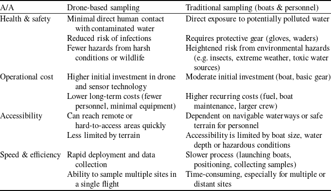


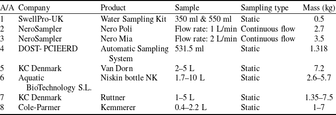
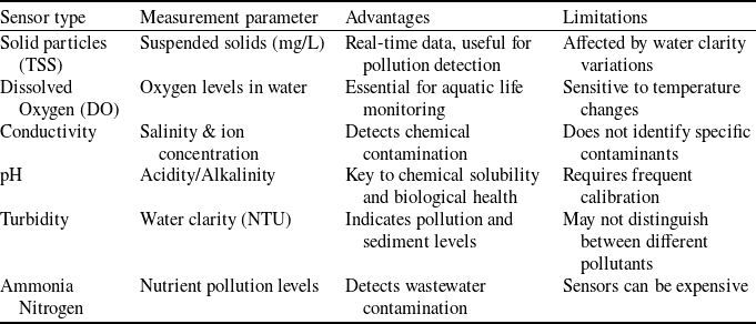


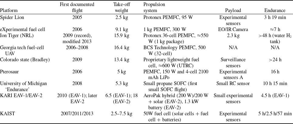
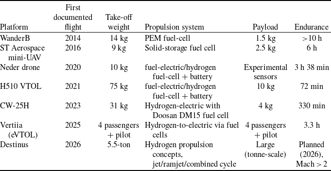

 Open access

