Introduction
Microstrip antennas offer a host of compelling advantages, including low profile, compact size, easy integration with electronic devices, cost-effectiveness, and simple fabrication [Reference Balanis1]. However, one notable drawback is their narrow bandwidth. To overcome this limitation, various techniques for broadening the bandwidth of microstrip antennas have been extensively explored and reported in prestigious journals. Wideband microstrip antennas are particularly beneficial, as they enable high data rates with low power spectral density [Reference Kumar and Ray2]. Additionally, these antennas can be made to generate circular polarization (CP) by modifying the radiating patch, adjusting the ground plane, utilizing slot geometry, or incorporating split-ring resonators, etc., as discussed in numerous renowned studies. CP plays a crucial role in reducing multi-path effects and eliminating antenna orientation restrictions [Reference Bala3]. This section has documented a variety of antenna types with various patch shapes, feed lines, slots, etc., that can significantly provide high gain, wideband, and CP characteristics. L-like strip and hook-like ground plane were used for wideband CP. A hook-shaped microstrip antenna for CP operation was reported in [Reference Samsuzzaman4]. CP was achieved by using monopole geometry with parasitic strips in [Reference Ding5]. L-shaped monopole antenna and falcate-like monopole antenna were reported for CP characteristics in [Reference Chandu6, Reference Xu7]. By using a modified ground plane, CPs were achieved in two cases [Reference Gyasi8, Reference Lee, Kim and Pyo9]. A C-like monopole with a modified feed line was responsible for 37.1% of axial ratio bandwidth (ARBW) in [Reference Kwame10]. A trapezoidal antenna provides 36% ARBW was published in [Reference Kumar11]. About 52% of ARBW has been achieved in [Reference Chen12]. A monopole antenna was proposed for 2.38–4.60 GHz ARBW in [Reference Kumar13]. 18.6% of ARBW was achieved in [Reference Li14]. The C-shaped slit was responsible for CP operations were informed in [Reference Xing15]. An ultrawideband antenna was responsible for CP operation in [Reference Midya16]. An antenna with CP operation was made up of a modified ground plane was published in [Reference Huang17, Reference Alsariera18]. The CP antenna is composed of a falcate-shaped monopole that has achieved an AR bandwidth of 94% in [Reference Xu19]. An ARBW of approximately 13.67% was informed for a T-like monopole antenna in [Reference Kumar20]. Simple monopole geometry provides CP operations for different wireless applications in [Reference Chandu21]. A coplanar waveguide-fed CP antenna with 62.6% ARBW was proposed in [Reference Zha22]. Parasitic loops were used for CP operation for a monopole antenna was informed in [Reference Feng23]. A proposed CP antenna used an inverted T-shaped patch was informed in [Reference Singh24]. A proposed structure consisting of a wide-slotted hexagonal geometry has been proposed for CP operation and has been reported in [Reference Kumar25]. In total, 102.6%, 62%, and 83.2% of ARBW were proposed for various applications in [Reference Zhu26–Reference Kumar28]. A wideband CP antenna was proposed for the global satellite navigation system in [Reference Wang29]. A compact antenna provides multiple bands and dual CP for navigation systems in [Reference Chen30]. A microstrip antenna uses dipole fractal geometry was suggested for small satellite applications in [Reference Simón31]. A CP antenna supports GPS L1, L2, and L5 bands were reported in [Reference Mishra32]. A small antenna uses fractal patch and slots to obtain the CP operation was proposed for navigation systems in [Reference Wang33]. A wideband suggested antenna useful in satellite and other communication systems was informed in [Reference Mukherjee34]. An investigation of performance on microstrip antennas was done for satellite applications in [Reference Mercy35]. Using L-like microstrip feed line, a monopole antenna provides wideband CP in [Reference Bag36]. A Wideband CP antenna array was proposed for CP operation in [Reference Guthi37]. A planar monopole CP antenna with simple radiator structure was proposed in [Reference Park38]. A metasurface-based broadband CP antenna was proposed in [Reference Ding39].
This article reports on a planar simple antenna configuration that produces wideband CP using a modified C-shaped radiating strip and a truncated ground plane. The suggested planar monopole antenna was designed and optimized using the High Frequency Structure Simulator (HFSS). The simulated and experimental findings are compared to ascertain the proposed antenna’s correctness. The suggested antenna’s wide impedance bandwidth (IBW) (−10 dB) and AR (3 dB) bandwidth are finally obtained by simply scaling the different dimensions of radiating patch and slot of the ground plane. Our proposed work provides simple and easy geometry. It uses a single-layer substrate. Without using any complex geometry, it provides wide −10 dB IBW and 3 dB ARBW. Also, without using any frequency selective substrate, metasurface, array, and stacked substrate, it provides high gain. Due to low profile and above said characteristics, the proposed antenna may be useful in the various wireless systems.
Antenna structure
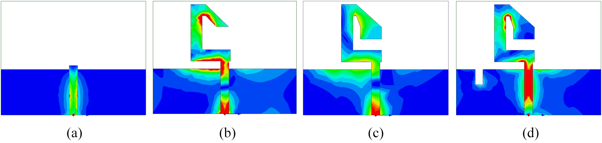
Figure 1(a) depicts the geometry of the proposed antenna structure. The snapshot of the fabricated proposed antenna is shown in Figure 1(b). Software HFSS is used to design the antenna. It comprises a modified C-shaped radiating patch and a partial rectangular ground plane with a narrow open-ended slot. The FR4 dielectric substrate material, with a height (h) of 1.6 mm, a relative permittivity (εr) of 4.4, and a loss tangent (tanδ) of 0.023, is used for the design of the proposed antenna. The antenna is excited using the microstrip feed line. Table 1 lists all the proposed antenna’s dimensions. The development steps of the proposed antenna (Antenna1 to Antenna4) are depicted in Figure 2. Four steps are designed for the development process (Antenna1 to Antenna4). Antenna1 (Figure 2(a)) is the first step where only the microstrip feed-line has been taken. It does not provide any IBW and any ARBW. A C-like patch is connected to Antenna1 to design Antenna2 in Figure 2(b). Antenna2 provides (4.91–7.23) GHz = 2.32 GHz bandwidth with (5.73–6.55) GHz = 0.820 GHz ARBW. Antenna3 connects a rectangular patch with the slant portion of Antenna2 in Figure 2(c). Antenna3 provides (4.11–7.06) GHz = 2.95 GHz bandwidth with (3.92–6.36) GHz = 2.44 GHz ARBW. Next, to design Antenna4, a tiny open-ended slot is added to the ground plane to improve the ARBW. Figure 2(d) explains Antenna4. Antenna4 provides (4.11–6.80) GHz = 2.69 GHz −10 dB IBW with (4.25–6.92) GHz = 2.67 GHz 3 dB ARBW. The comparison of the simulated reflection coefficient versus frequency and the axial ratio versus frequency of different steps of the proposed antenna is plotted in Figure 3(a) and (b), respectively. After a thorough comparison of the results across all steps, Antenna 4 emerged as the optimal choice, primarily due to its superior ARBW.
(a) Geometry of the proposed antenna. (b) Fabricated proposed antenna.

Development steps of the proposed antenna. (a) Antenna1. (b) Antenna2. (c) Antenna3. (d) Antenna4 (proposed antenna).

The comparison of the simulated (a) reflection coefficient versus frequency and (b) axial ratio versus frequency for different steps of the proposed antenna.

Dimensions of the proposed antenna (in mm)

Method of design and circular polarization characteristics
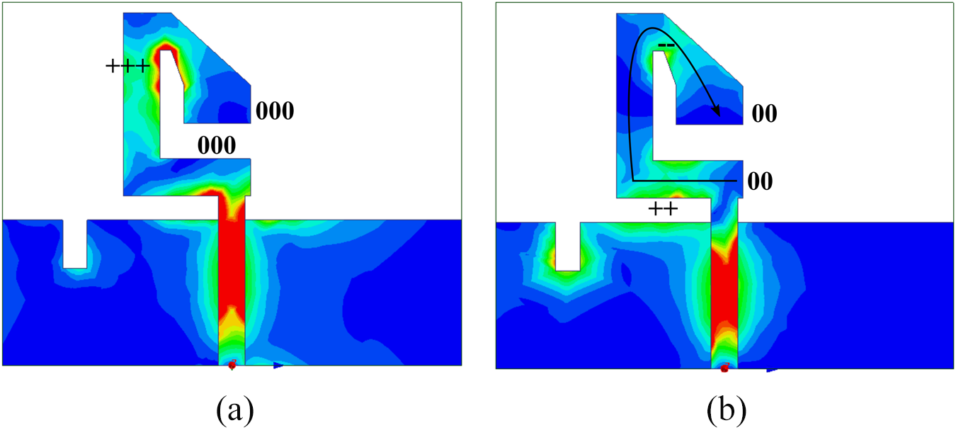
In the proposed antenna (Figure 4(a)), the surface current distribution on a C-shaped strip at 4.5 GHz is explored as zero-peak-zero, and the electrical length turns out to be one, where  $\frac{{{\lambda _g}}}{2}$is the guided wavelength of the desired resonant frequency. Therefore, the length obtained from the current distribution plot (Figure 4(a)) is 22.18 (L2 + L3 + L9 + {
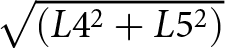 $\sqrt {(L{4^2} + L{5^2})} $+
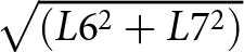 $\sqrt {(L{6^2} + L{7^2})} $}/2) mm….(i). The dimensions are clearly mentioned in Figure 1 and Table 1, for the above equation (i) and from the reflection coefficient plot (Figure 3(a)), the length is calculated, and it becomes 19.88 mm, which is approximately equal to
 $\frac{{{\lambda _g}}}{2}$. Similarly, in the proposed antenna (Figure 4(b)) at 6.2 GHz, the surface current distribution is assigned as zero-peak-zero-peak, the electrical length turns out to be one guided wavelength
 $({\lambda _g})$. Therefore, the length from the current distribution (Figure 4(b)) is 32.71 (L1 + L2 + L3 + L9 +
 $\sqrt {(L{4^2} + L{5^2})} $ +
 $\sqrt {(L{6^2} + L{7^2})} $) mm and from the reflection coefficient plot (Figure 3(a)) it becomes 29.50 mm
 $({\lambda _g})$. Two resonant frequencies (4.5 and 6.2 GHz) are obtained by using equation fr =
 $\frac{c}{{{\lambda _g}\sqrt {\frac{{{\varepsilon _r} + 1}}{2}} }}$, where fr is the resonant frequency, c is the speed of the light and εr is the dielectric constant of the substrate. Now, these two resonant frequencies are merged together and produce wide-bandwidth (2.69 GHz).
Surface current distribution of the proposed antenna at (a) 4.5 GHz and (b) 6.2 GHz.

On the other hand, the proposed antenna exhibits wide CP. For CP, E-field components (Ex and Ey) should have equal in magnitude and ± 90° phase difference between them. These two criteria are graphically shown in Figure 5, where the magnitude is approximately equal to one, and the phase difference is approximately equal to —90° within the operating range. The magnitude ratio and phase difference with respect to frequency of the proposed antenna are shown in Figure 5.
Magnitude ratio and phase difference plot of the proposed antenna.

The concept of CP of the proposed antenna at two resonant frequencies (4.5 and 6.2 GHz) is described by using surface current distributions which are shown in Figures 6 and 7. To more the top and ground plane surface current distribution helps to explain the CP mechanism. For that, the surface currents are distributed by the vector components. Figures 6 and 7 illustrate the surface current at 4.5 and 6.2 GHz for two consecutive angular values (ωt = 0° and ωt = 90°) over one complete rotation of 360°. Therefore, the rotation of the resultant vector sum dictates the orientation [whether it is left-hand circular polarization (LHCP) or right-hand circular polarization (RHCP)] of CP. The resultant surface current (J_sum) consists of the top C-shaped plate and the ground plane. At 4.5 GHz, Figure 6 shows that the resultant vector lies along (‒X‒Y) direction at ωt = 0°, then it rotates in clockwise direction and directed along (‒X+Y) direction at ωt = 90°. Hence, at 4.5 GHz, from the rotation of the resultant surface current, it is concluded that the LHCP wave is produced in + Z direction. Similarly, at 6.2 GHz, Figure 7 shows that the resultant vector lies along (‒Y) direction at ωt = 0°, then it rotates in clockwise direction and directed along (‒X) direction at ωt = 90°.
Surface current distribution of the proposed antenna at 4.5 GHz for (a) ωt = 0° and (b) ωt = 90°.

Surface current distribution of the proposed antenna at 6.2 GHz for (a) ωt = 0° and (b) ωt = 90°.

Parametric analysis
A thorough parametric study was carried out to assess how antenna dimensions affect CP features and wideband performance. For this research, the key parameters taken into account are L8, L9, L12, and L13. To isolate each parameter’s unique influence, HFSS simulations were used to change each one separately while holding the others constant. Figures 8–11 depict the reflection coefficients and axial ratios, while Tables 2–5 provide a summary of the findings, including the IBW, its percentage, and the ARBW and its percentage for every parameter variation.
Parametric study for L8 (a) reflection coefficient plot and (b) axial ratio plot.

Parametric study for L9 (a) reflection coefficient plot and (b) axial ratio plot.

Parametric study for L12 (a) reflection coefficient plot and (b) axial ratio plot.

Parametric study for L13 (a) reflection coefficient plot and (b) axial ratio plot.

Results of parametric study for L8

Results of parametric study for L9

Results of parametric study for L12

Results of parametric study for L13

Influence of L8
Plots of the axial ratio and reflection coefficient for different values of L8 (3.53, 4.53, 5.53, and 6.53 mm) with all other parameters held constant are shown in Figure 8(a) and (b). The IBW continuously improves as L8 increases. On the other hand, the ARBW stays constant for the first two values, maximum at L8 = 5.53 mm, which is 2.67 GHz, and then starts to drop at L8 = 6.53 mm. L8 = 5.53 mm is determined to be the optimal dimension because ARBW is a crucial parameter in this investigation.
Influence of L9
Figure 9(a) and (b) show the performance variations with L9 values ranging from 1.18 to 5.18 mm in 1 mm increments. As L9 increases, a significant improvement in IBW is observed. The ARBW also increases, reaching a maximum at L9 = 3.18 mm, after which it begins to decrease. Based on both the ARBW and the percentage of ARBW, L9 = 3.18 mm is selected as the optimal value for antenna fabrication.
Influence of L12
Figure 10(a) depicts that L12 does not significantly affect the IBW for 1 and 2 mm. However, further increases in L12 cause the antenna to exhibit a dual-band characteristic, which is undesirable for this application. Figure 10(b) shows that the maximum ARBW occurs at L12 = 2 mm. So, L12 = 2 mm is considered as optimal value for fabrication.
Influence of L13
The effects of L13 are displayed in Figure 11(a) and (b). For L13 values of 2, 3, and 4 mm, the antenna provides wide IBW. At L13 = 5 and 6 mm, dual-band nature is observed, which is undesirable in this design. Among the five values studied, L13 = 4 mm yields the best IBW and ARBW, making it the final choice for the proposed fabricated design.
After parametric study, the optimal values that are chosen for antenna fabrication are L8 = 5.53 mm, L9 = 3.18 mm, L12 = 2 mm, and L13 = 4 mm.
Result and discussion
The simulated and measured results of the proposed antenna have been discussed here, and the results are tabulated in Table 6. Figure 12(a) presents the reflection coefficient (in dB); illustrating the antenna’s simulated IBW ranging from 4.11 to 6.8 GHz, which corresponds to 2.69 GHz IBW with 49.31% of IBW. Figure 12(b) depicts the ARBW ranging from 4.25 to 6.92 GHz, providing a simulated 2.67 GHz ARBW with 47.80% of ARBW. As shown in Figure 12(c), the antenna reaches a peak simulated gain of 8.13 dBi at 6.0 GHz. In case of measurement results, the antenna provides an IBW of 2.88 GHz (4.24 to 7.12 GHz), which is 50.70% of IBW. The measured 3 dB ARBW ranges from 4.3 to 6.8 GHz, resulting in a 2.5 GHz ARBW and 45.04% ARBW. Additionally, a peak measured gain of 7.4 dBi is obtained at 6.0 GHz. Figure 13 depicts the simulated radiation patterns of the proposed antenna at 4.5 GHz for φ = 0° and φ = 90° planes, providing RHCP and LHCP characteristics.
The simulated and measured results of the proposed antenna (a) reflection coefficient versus frequency plot, (b) axial ratio versus frequency plot, (c) gain versus frequency plot, and (d) measurement of the fabricated antenna.

Radiation patterns of the proposed antenna at 4.5 GHz (a) φ = 0° and (b) φ = 90°.

Comparison between simulated and measured results of the proposed antenna

A comparative study between the proposed work and the studies discussed in the introduction has been done here, providing parameters such as size, bandwidth, 3 dB ARBW, and peak gain. The results of this comparison are presented in Table 7. The results of the comparison indicate that the proposed antenna delivers superior performance compared to the other works discussed.
Comparison of previous antennas in terms of performance

Conclusion
A C-shaped monopole antenna with a wideband and CP has been introduced in this research study. The antenna consists of a modified C-shaped strip with a small open-ended ground-plane notch. The CP is activated by switching the surface current distribution by interlacing a ground plane and a C-shaped strip. Wide ARBW is achieved by adjusting the ground plane and patch dimensions. The measured fractional bandwidth and ARBW are 50.70% and 45.04%, respectively. The proposed antenna has also produced a measured peak gain of 7.4 dBi. Due to its small size, easy structural design, and wideband CP characteristics, the antenna may be a suitable choice for different wireless communication systems.
Funding statement
This research received no specific grant from any funding agency, commercial or not-for-profit sectors.
Competing interests
The authors report no conflict of interest.

Susmita Bala received her M.Tech degree from Jadavpur University, West Bengal, India. She received Ph.D. degree in Engineering from the Department of Engineering and Technological Studies, University of Kalyani in the year 2023. She is currently working as an Assistant Professor at the Department of Electronics, Vidyasagar University. Her research interests include microstrip antenna design for wireless communication systems.

Biplab Bag received his M.Tech degree from West Bengal University of Technology, West Bengal, India. He received Ph.D. degree in Engineering from the Department of Engineering and Technological Studies, University of Kalyani in the year 2021. He is currently working as an Assistant Professor at the Department of Electronics and Communication Engineering, Haldia Institute of Technology. His research interests include microstrip antenna design for wireless communication systems and FSS design.

Sushanta Sarkar received his M.Tech degree from Kalyani Govt. Engineering College in the year 2010. He received Ph.D. degree in Engineering from the Department of Engineering and Technological Studies, University of Kalyani in the year 2015. He is currently working in the rank of Assistant Professor at the Department of Engineering and Technological Studies, University of Kalyani.

Partha Pratim Sarkar received his M.E. degree from Jadavpur University in the year 1994. He received Ph.D. degree in Engineering from Jadavpur University in the year 2002. He is currently working in the rank of Professor at the Department of Engineering and Technological Studies, University of Kalyani. His areas of research include microstrip antenna, microstrip filter, frequency selective surfaces, and artificial neural network.