Introduction
Molecular spintronics devices are considered a strong candidate for developing futuristic logic and memory devices.[Reference Miao, Munzenberg and Moodera1] A versatile form of molecular spintronics devices can be produced by utilizing a magnetic tunnel junction as the testbed. Utilization of a magnetic tunnel junction with the exposed side edges for enabling the bridging of molecular channels between two ferromagnetic electrodes along the junction edges offer tremendous advantages over conventional methods.[Reference Tyagi2, Reference Tyagi, Friebe and Baker3] Suitability and properties of the magnetic tunnel junction test bed mainly depend on the electrode materials and the insulating spacer or tunnel barrier. Study of magnetic tunnel junction literature suggests that various insulating spacers or tunneling barrier lead to different magnetoresistance like properties.[Reference Yuasa and Djayaprawira4] Past literature also provides a vast knowledge with regard to the impact of ferromagnetic electrodes on the impact of magnetic tunnel junction properties. A few studies have suggested the impact of adding tantalum (Ta) layer on the ferromagnetic electrode.[Reference Kezilebieke, Ali, Shadeke and Gunnella5] Prior work suggests that deposition of Ta layer on a NiFe like a ferromagnet produced a dead layer.[Reference Kowalewski, Butler, Moghadam, Stocks, Schulthess, Song, Thompson, Arrott, Zhu, Drewes, Katti, McClure and Escorcia6] However, prior literature provides limited insight about the impact of Ta top layer on the magnetic tunnel junction. Here we present our study focusing on the Ta impact on a magnetic tunnel junction with Ta(2 nm)/Co(5 nm)/NiFe (5 nm)/AlOx(2 nm)/NiFe (10–15 nm) configuration. Here we also discussed that Ta's subtle impact on magnetic tunnel junction resulted in significant impact on magnetic tunnel junction-based molecular spintronics devices.
Experimental details
We produced magnetic tunnel junction pillars with the exposed side edges to transform them into molecular spintronics devices. To avoid the undesirable impact of edges we produced the magnetic tunnel junction with several tens of micron area. We fabricated an array of ~7000 patterned magnetic tunnel junctions per sample. Every magnetic tunnel junction was ~5 µm in diameter. The distance between nearest neighbor magnetic tunnel junction was ~10 µm. We utilized an oxidized silicon substrate and performed photolithography to produce a photoresist layer with an array of micro-cavities. For this study, Shipley® (S1813) photoresist was spin coated on an oxidized silicon wafer piece at 3000 rpm speed. This spin-coated photoresist film was baked at 90 °C for 1 minute. Subsequently, the photoresist was exposed to UV light through a photomask containing an array pattern. We developed the photoresist film in MF 319 Microposit developer to produce an array of microcavities in the photoresist film. These microcavities were filled with multiple thin films to create an array of magnetic tunnel junctions. Tantalum (Ta), cobalt (Co), alumina (AlOx), and NiFe alloy with 80% nickel were sputter deposited with AJA International sputtering machine. We first sputter deposited Ta(2 nm)/Co(5 nm)/NiFe (5 nm)/AlOx(2 nm)/NiFe (10–15 nm) thin film configuration. This magnetic tunnel junction configuration is named as MTJ. To prepare the sample for the study of Ta impact the MTJ-Ta samples were produced. To create MTJ-Ta samples, we additionally sputter deposited 5 nm Ta on the top of MTJ configuration. A resultant MTJ-Ta sample had Ta(2 nm)/Co(5 nm)/NiFe (5 nm)/AlOx(2 nm)/NiFe (10–15 nm)/Ta (5 nm) configuration. The Ra roughness of the completed MTJ was determined to be ~2 nm. To produce a good coverage we kept Ta thickness above 2 nm. We obtained statistically no difference in MTJ-Ta attributes due to variation in Ta thickness from 4 to 6 nm. However, deposition of Ta thickness >6 nm produced rather unstable MTJ-Ta; presumably thicker Ta produced higher mechanical stresses that affected the MTJ-Ta stability. Due to the abovementioned considerations, we produced ~5 nm Ta top layer thickness to ensure a conformal film yielding stable MTJ-Ta samples. These MTJ and MTJ-Ta samples were characterized by the X-band Bruker EMX300 FMR and NanoOsc Phase FMR over 2−17 GHz frequency range at room temperature. Magnetization studies were performed with Quantum Design PPMS SQUID magnetometer at 150 K. Low temperature was chosen to avoid noise in the magnetization study. Polarized Neutron Reflectivity (PNR) study was performed at 150 K and at 150 mT magnetic field at National Institute of Standards and Technology, Gaithersburg, USA. It is noteworthy that to avoid signal from the insulating substrate during PNR study the unpatterned magnetic tunnel junctions were made with and without Ta on top.
Results and discussions
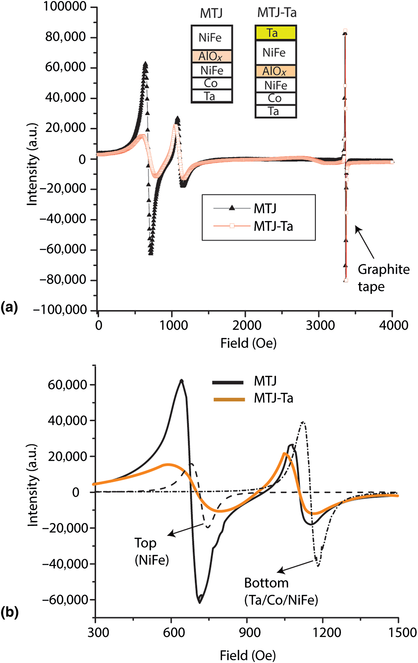
We first studied the MTJ and MTJ-Ta with FMR technique. FMR is a powerful tool to study the characteristics of magnetic coupling between two magnetic structures, especially two ferromagnetic films.[Reference Baberschke7] Our FMR studies revealed a clear difference between MTJ and MTJ-Ta (Fig. 1). Under the identical experimental conditions, both samples showed two distinct FMR modes. For both samples, an in-plane DC magnetic field up to 4000 Oe and 9.75 GHz microwave was applied to study the resonance modes [Fig. 1(a)]. Before every measurement, the cavity's spectra were checked for the background signal at fivefold higher gain than that used for the MTJ and MTJ-Ta samples. We also utilized the FMR response from the graphite tape as a control sample to ensure that experimental conditions were identical for the MTJ and MTJ-Ta [Fig. 1(a)]. During the FMR study of MTJ and MTJ-Ta, the graphite tape produced a delta function type resonance peak at 3367 ± 4 Oe (Fig. 1). In our study, we utilized the same graphite tape to mount the MTJ and MTJ-Ta samples for the FMR study. This sharp resonance peak from the graphite tape was statistically identical for the MTJ and MTJ-Ta samples [Fig. 1(a)]. Invariance of the graphite tape's signal suggests that experimental conditions for measuring MTJ and MTJ-Ta were identical. The reproducibility of the graphite tape's resonance signal ensured the robustness and reproducibility of microwave power, DC magnetic field, and losses due to the measurement system, etc. The MTJ sample showed acoustic mode (higher intensity resonance peak) before the optical mode (lower intensity peak) [Fig. 1(a)]. According to FMR theory correlating the FMR mode positions to the inter-electrode exchange coupling[Reference Geshev, Pereira and Schmidt8, Reference Linder and Baberschke9] two ferromagnetic electrodes of the MTJ sample are antiferromagnetically coupled. On the other hand, the two resonance peaks from MTJ-Ta sample were significantly different as compared with the FMR peaks from MTJ. It appears that the presence of Ta on the top of NiFe ferromagnetic electrode reduced the intensity of the first resonance peak [Fig. 1(a)]. As a result, MTJ-Ta exhibited smaller intensity resonance mode (optical mode) appearing before the higher intensity resonance (acoustic mode). This particular form of the FMR spectra from MTJ-Ta is indicative of ferromagnetic coupling between the two ferromagnetic electrodes.[Reference Geshev, Pereira and Schmidt8] We estimated the strength of exchange coupling between two ferromagnetic electrodes of the MTJ and MTJ-Ta to be of the similar magnitude. We evaluated the slope of the lines joining the two resonance modes of the MTJ and MTJ-Ta [Fig. 1(b)]. It is noteworthy that zero slope means no interaction between the two ferromagnetic electrodes. The FMR modes recorded on the isolated top and bottom ferromagnetic electrodes are uncoupled [Fig. 1(b). However, for MTJ and MTJ-Ta the slope of the line between two modes are quite similar.
(a) FMR spectra recorded on MTJ and MTJ-Ta samples. (b) FMR spectra for MTJ and MTJ-Ta compare with the FMR spectra of the isolated top (NiFe) and bottom (TaCoNiFe) ferromagnets.

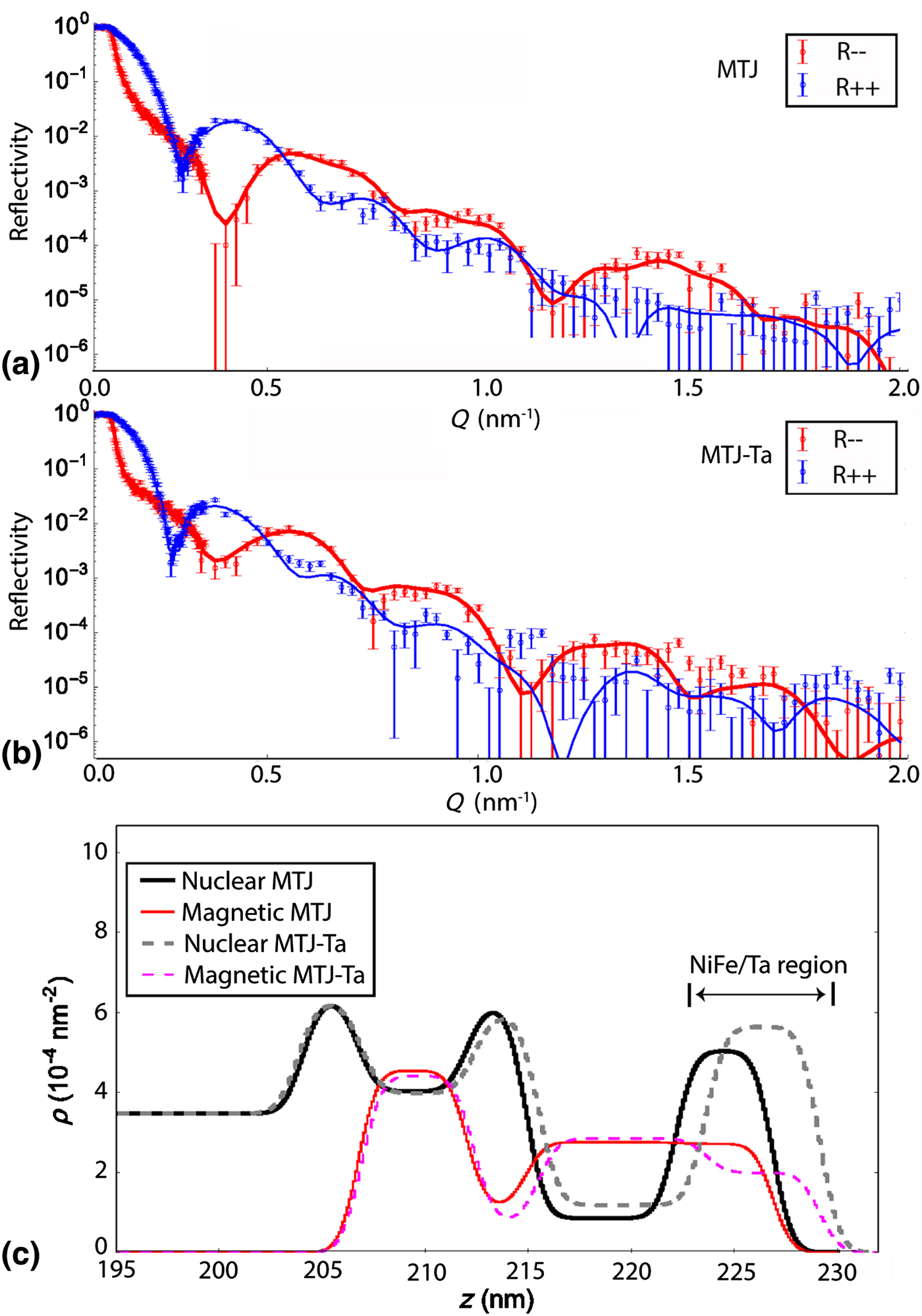
To understand the impact of Ta along the depth of the MTJ, we conducted PNR studies. We hypothesized that the magnetic attributes of the MTJ's top electrode should be affected by the Ta layer. We employed PNR to investigate the difference in magnetic attributes of the MTJ and MTJ-Ta. Under this experiment, a polarized beam of neutrons interacted with the MTJ and MTJ-Ta. Subsequently, the spin and angle of the neutron beam reflected by the samples were analyzed. We utilized nuclear reflectivity and non-spin flip reflectivity to calculate R— and R++ obtained from MTJ [Fig. 2(a)] and MTJ-Ta [Fig. 2(b)]. Here, R— corresponds to the difference in reflectivity from nuclear and magnetic profiles. Whereas, the R++ correspond to the sum of reflectivity due to nuclear and magnetic profiles. We fitted the experimental data with the scattering length density model to record the depth-wise changes in MTJ and MTJ-Ta magnetization [Fig. 2(c)]. For MTJ-Ta magnetic signal in the 220–230 nm thickness range suggests that Ta gained magnetic moment. However, the magnetization in the adjacent NiFe's region decreased; the NiFe/Ta region for the magnetic signal in Fig. 2(c) indicates this possibility. However, for the MTJ sample magnetic signal for the top NiFe electrode has the expected profile in the 220–230 nm thickness range [Fig. 2(c)]. This PNR observation is in agreement with the prior studies which reported that a Ta film deposited on the NiFe gained magnetic moment.[Reference Kezilebieke, Ali, Shadeke and Gunnella5, Reference Kowalewski, Butler, Moghadam, Stocks, Schulthess, Song, Thompson, Arrott, Zhu, Drewes, Katti, McClure and Escorcia6] The reduction in magnetic moment of top NiFe electrode is also in agreement with the decrease in the intensity of the acoustic mode of MTJ as compared with MTJ-Ta (Fig. 1). Ta is found to acquire ~0.34–0.56 µB magnetic moment when deposited on NiFe surface.[Reference Kezilebieke, Ali, Shadeke and Gunnella5, Reference Kowalewski, Butler, Moghadam, Stocks, Schulthess, Song, Thompson, Arrott, Zhu, Drewes, Katti, McClure and Escorcia6] These Ta atoms established antiferromagnetic coupling with the Ni atoms near the NiFe surface region. This antiferromagnetic coupling between the acquired magnetic moment in Ta and Ni atoms near the NiFe surface yielded a dead layer of ~2 nm thickness that does not possess any net magnetic moment.[Reference Kowalewski, Butler, Moghadam, Stocks, Schulthess, Song, Thompson, Arrott, Zhu, Drewes, Katti, McClure and Escorcia6]
Polarized beam neutron reflectivity study of (a) MTJ and (b) MTJ-Ta samples. Solid line show fitted curve on the experimental data. R–correspond to reflectivity from nuclear profile minus reflectivity from magnetic profile. R++ corresponds to reflectivity from the nuclear profile plus reflectivity from magnetic profile. (c) Nuclear and magnetic scattering length density (ρ) versus MTJ and MTJ-Ta thickness.

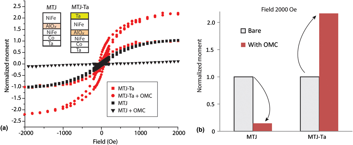
We also investigated the difference in magnetization data obtained from the MTJ and MTJ-Ta. We found that both samples produced almost identical magnetization loops [Fig. 3(a)]. However, MTJ-Ta was relatively less sloped in the unsaturation state [Fig. 3(a)]. This Ta induced subtle difference in the magnetization loop affirms two important points: (i) For MTJ the antiferromagnetic inter-ferromagnetic electrode coupling is not strong otherwise there could be a significant change in the magnetization loop[Reference Demokritov10]; (ii) magnetization data for MTJ-Ta showed moderate increase in the magnetic moment between saturation states as compared with that of MTJ (Fig. 2).
(a) Magnetic moment of MTJ and MTJ-Ta before and after treating with OMCs. (b) Magnetization data at 2000 Oe showing the impact of OMCs on MTJ and MTJ-Ta.

After the investigation of the effect of Ta on MTJ magnetic properties, we studied MTJ and MTJ-Ta-based molecular devices. We studied the impact of Ta top layer on the magnetic properties of the magnetic tunnel junction-based molecular devices (MTJMSD). The MTJMSD were produced by bridging the paramagnetic molecules between the ferromagnetic electrodes of the MTJ and MTJ-Ta.[Reference Tyagi, D'Angelo and Baker11] These paramagnetic molecules are organometallic molecular clusters (OMCs).[Reference Li, Parkin, Wang, Yee, Clerac, Wernsdorfer and Holmes12] The method of molecule attachment was described elsewhere.[Reference Tyagi, Baker and D'Angelo13, Reference Tyagi, Li, Holmes and Hinds14] The attributes of OMC paramagnetic molecules have also been published elsewhere.[Reference Li, Parkin, Wang, Yee, Clerac, Wernsdorfer and Holmes12] An OMC molecule contained an octa-nuclear cubic cage with a net spin state. Every corner of the OMC's cubic cage possessed an alkane tether. At the end of each alkane tether, a thiol functional group was provided. The thiol functional groups helped to bridge the molecules across the ~2 nm AlOx tunnel barrier along the exposed edges of the tunnel junctions. Each thiol group had a strong affinity towards the NiFe ferromagnetic electrode of the MTJ and MTJ-Ta. The magnetic study performed at 150 K showed that OMCs created remarkably stronger exchange coupling as compared with AlOx tunnel barrier (Fig. 3).
The substantial impact of OMC is depicted by the emergence of linear magnetization data on MTJ treated with OMCs [Fig. 3(a)]. The linear magnetization response from OMC treated MTJs (MTJ + OMC) was significantly different from the typical magnetization loop observed on bare MTJs [Fig. 3(a)]. On the other hand, the strong impact of OMC is represented by the emergence of a larger magnetization loop on MTJ-Ta treated with OMCs [Fig. 3(a)]. It is noteworthy that MTJ and MTJ-Ta samples contained several thousand tunnel junctions to yield the high signal to noise ratio during magnetic studies. To study the paramagnetic OMC effect the magnetic moment were measured for ±2000 Oe field range. The magnetization study showed that OMC channels across the AlOx insulator on the exposed sides produced the opposite effects on MTJ and MTJ-Ta [Figs. 3(a) and 3(b)]. The magnetic moment of MTJ dropped nearly by ~84% [Fig. 3(b); it must be noted that according to FMR data MTJ had preexisting antiferromagnetic coupling between the ferromagnetic electrodes. On the other hand, OMCs increased the magnetic moment of the MTJ-Ta by ~116% [Fig. 3(b)]; it is noteworthy that according to FMR data MTJ-Ta possessed pre-existing ferromagnetic coupling between the two ferromagnetic electrodes (Fig. 1). This study indicates that preexisting exchange coupling, even though very weak, is important in determining the magnetic properties of the molecular spintronics devices. It appears that OMC amplified the preexisting inter-layer exchange coupling between the ferromagnetic electrodes of the MTJ and MTJ-Ta magnetic tunnel junctions.
Conclusions
This paper discussed the impact of the Ta layer on the magnetic properties of the magnetic tunnel junction-based molecular spintronics devices. FMR was found to be useful in recording the subtle changes due to the addition of Ta layer. We also conducted neutron scattering studies on MTJ and MTJ-Ta samples. The neutron study observed the moderate change in the magnetic attributes in the top Ta layer and neighboring NiFe region. We found that ferromagnetic resonance is extremely sensitive for studying the effect of the change in electrode composition on the inter-electrode exchange coupling. It was also found that the ability to change the nature of inter-electrode coupling of a magnetic tunnel junction can impact the resulting properties of the molecular spintronics devices. We observed that paramagnetic molecules decreased the magnetic moment of the MTJ with pre-existing antiferromagnetic coupling. However, the same paramagnetic molecules increased the magnetic moment of the MTJ-Ta with preexisting ferromagnetic exchange coupling.
Acknowledgments
Pawan Tyagi thank Dr. Bruce Hinds and Department of Chemical and Materials engineering at the University of Kentucky for facilitating experimental work on molecular spintronics during his Ph.D. OMC was produced by Dr. Stephen Holmes's group. The preparation of this paper and complementary experiments were in part supported by the National Science Foundation-Research Initiation Award (Contract # HRD-1238802) and Air Force Office of Sponsored Research (Award #FA9550-13-1-0152). We also thank Centre of Nanoscience and Technology, NIST Gaithersburg for allowing the use of microscopy resources. We also acknowledge Dr. Brian Kirby of NIST Center of Neutron Reflectivity for the polarized beam reflectivity study. We also thank the STEM Center at UDC for providing the partial funding. Any opinions, findings, and conclusions expressed in this material are those of the author(s) and do not necessarily reflect the views of any funding agency and corresponding author's affiliations and collaborators.