Introduction
Antennas for wireless communication systems have played an important role in every sector. The demand for compact and multiband antennas is growing due to the newly expanding microwave and mobile communication systems [Reference Matin1], such as that used in 5G base stations and mobile phones. This exhaustive use of the radio-electric spectrum has generated a great interest in devices, making it possible to cover several bands simultaneously. The 5G spectrum covers from sub-6 GHz up to millimeter-wave frequencies. For civil, military, satellite, and underwater applications, the 5G antenna should be operated at wide and/or multiple frequency bands. Due to the disparity of the frequency band, antennas designed for a 5G communication system face enormous challenges. The antenna for 5G must be compacted enough to be implanted in portable devices [Reference Fallahpour and Zoughi2]. Moreover, as the sub-6 GHz antenna has to work along with the current long-term evolution LTE and other service bands, the 5G antenna should cover the sub-6 GHz bands and the existing WiMAX, WLAN, and LTE bands. Among different categories of antenna. Microstrip patch antenna becomes the appropriate optimal due to their attractive low-profile features, lightweight, inexpensive, and easy integration [Reference Balanis3].
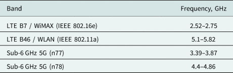
On the other hand, different techniques have been reported to achieve multiband compact antennas [Reference Konkyana, Lalitha and Sudhakar4–Reference Fertas, Challal and Fertas6]. Authors in [Reference Fertas, Tebache, Ghanem, Tedjini and Aksas5] proposed a non-conventional multiband patch antenna design based on a Genetic Algorithm with a filtering aspect. Based on different fundamental steps, the developed script was performed to achieve good impedance bandwidth in frequency bands [3.7/5.5 and 7.2 GHz] that correspond to WiMAX/WLAN and X-band standards, respectively. In [Reference Fertas, Challal and Fertas6] and [Reference Haque and Parvez7] it was examined that the miniaturized antennas were based on Slot structure, and slit loading techniques. In [Reference Boutejdar, Challal, Bennani, Mouhouche and Djafri8], a modified rectangular patch antenna with U-shaped defected ground structure (DGS) unit and two parasitic elements for WLAN, WiMAX, C, and X bands applications were described. The application of metamaterials to improve the performance of small antennas has been reported in many published works. In [Reference Liu, Guo, Zhao, Huang, Li and Yin9], a metasurface composed of pairs of nonuniform cut wires with different lengths is proposed to reduce the mutual coupling of an extremely compact dual-band two-element MIMO antenna array. The isolation between two patch antennas with the edge-to-edge spacing of only 0.008 wavelengths can be enhanced to more than 25 dB at both 2.6 and 3.5 GHz bands. In [Reference Fertas, Challal and Fertas10], a miniaturized multiband antenna for Bluetooth, WLAN, WiMAX, LTE, and X band applications was reported. In [Reference An and He11], a planar antenna for a 5G mobile terminal operating at sub-6 GHz was presented. The antenna consists of three ground strips and a driven strip which has a –6 dB impedance bandwidth of 700–960 MHz and 1.6–5.5 GHz. However, a large ground plane of 135 × 80 mm2 is required. An ellipse-shaped patch antenna for LTE-R and 5G mid-band was described in [Reference Arya, Kim and Kim12]. With an overall dimension of 180 × 60 mm2, the developed antenna has a dual band response of 660–790 MHz and 3.28–3.78 GHz. A dual-polarized magneto-electric dipole antenna for 5G communication applications was reported in [Reference Sun, Li and Xia13]. The investigated antenna is made up of four horizontal fishtail-shaped patches and four vertical patches that are shorted to the ground. With an overall dimension of 150 × 150 mm2, the antenna achieved an operational band of 3.05–4.42 GHz. However, it does not cover the N79 for the 4.4–5 GHz range. A monopole antenna for 4G/5G applications was introduced in [Reference Khalifa, Khashan, Badawy and Ibrahim14]. The investigated single-element antenna achieves operating bands of 1.24–2.64 and 3.34–5 GHz. Nevertheless, because of its large size of 150 × 80 mm2, it cannot cover the N79 band. A planar antenna for 2G/3G/4G/5G sub-6 GHz applications was reported in [Reference Sekeljic, Yao and Hsu15]. A − 6 dB impedance bandwidth of 2.5–4.8 GHz with a dimension of 50 × 19.75 mm2 was obtained. However, a large ground plane of 110 × 50 mm2 is required. In [Reference Tang, Jiao, Li, Zong, Yao, Shan and Gao16], an UWB antenna for 5G lower band application was described. With an overall dimension of 80 × 50 mm2, the examined design was able to function in the 2.32–5.24 GHz range. In [Reference Jin, Deng, Yang, Xu and Liao17], a differential fed frequency reconfigurable antenna for mid-band 5G applications was presented. The developed antenna uses two different substrates, and the reconfigurability was achieved via four PIN diodes. The examined antenna, with an overall volume of 100 × 100 × 5.7 mm3, achieved dual operating bands of 2.37–2.67 and 3.39–3.62 GHz. Its 3D shape, however, limits its application in mobile devices. Besides, it does not cover the whole sub-6 GHz 5G spectrum. In [Reference Saxena, Kanaujia, Dwari, Kumar and Tiwari18], a four-port MIMO antenna for 5G applications was investigated. The exhibited antenna, printed on a $50 : 50$ mm2 substrate, can only cover a 3.4–3.8 GHz frequency range. A dual-band MIMO antenna for mid-band 5G wireless applications was published in [Reference Ren and Zhao19]. Also, in [Reference Sultan, Ikram and Nguyen-Trong20], a dual-band with an enhanced impedance using a tapered slot is designed and studied. The antenna presents a very large frequency ratio, making it very suitable for integrated 4G/millimeter-wave, 5G, and beyond 5G applications. Two-antenna pairs are arranged vertically on two sides of the ground plane to produce dual bands of 3.4–3.6 and 4.8–5 GHz. Although many of the reported antennas accomplished wide/multiple operating bands [Reference Benmahmoud, Lemaitre-Auger and Tedjini21–Reference Benmahmoud, Lemaitre-Auger and Tedjini23], their 3D profile has a complicated geometry, making it hard to realize. Furthermore, some of the suggested designs partially cover the sub-6 GHz band. In this paper, a novel multiband compact antenna is proposed. The antenna is printed on FR-4 dielectric substrate with thickness of 1.5 mm, relative dielectric constant of 4.3, and loss tangent of 0.025. The simulated and measured return loss and radiation patterns are presented and discussed. The tested antenna provides acceptable results in terms of reflection coefficient and radiation patterns indicating that it is well-suited for 5G Sub-6 GHz (n77 / n78), WLAN, WiMAX, and LTE (B7/B46) wireless applications [Reference Penttinen24]. The target bands are summarized in Table 1.
Required frequency bands for the proposed antenna [Reference Saxena, Kanaujia, Dwari, Kumar and Tiwari18]

Antenna structure and design procedure
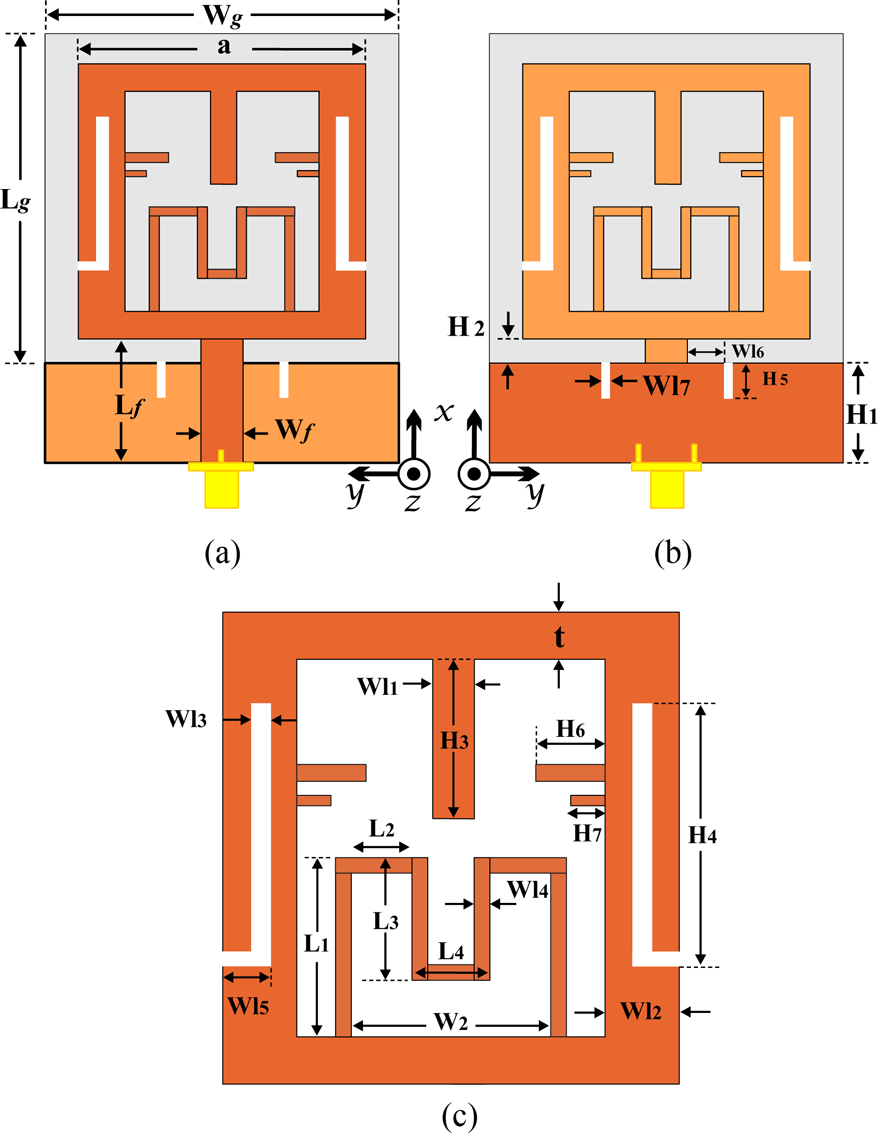
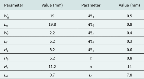
The configuration of the proposed antenna is shown in Fig. 1 whereas the geometrical dimensions are listed in Table 2. It consists of a single-step meander-line parasitic structure, parasitic stubs, and double inverted L-shaped defected microstrip structure (DMS) units on the top side of the substrate and double rectangular-shaped DGS units along with partial ground plane on the bottom side.
Geometry of the proposed antenna: (a) front view; (b) back view, and (c) patch view.

Geometrical dimensions of the proposed antenna

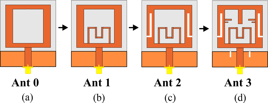
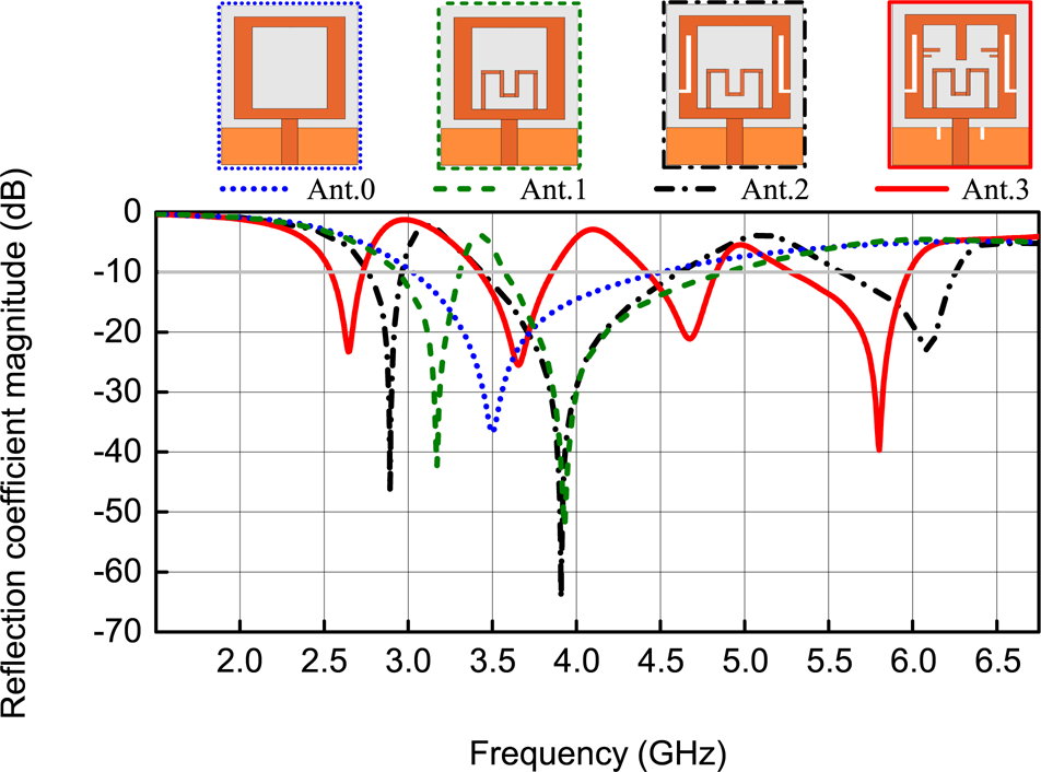
The step-by-step design evolution of the proposed antenna is shown in Fig. 2. Firstly, a square-ring metallic patch and a partial ground plane, operating at 3.5 GHz, is designed, using full-wave electromagnetic CST microwave simulator, denoted as reference antenna (Ant 0) as shown in Fig. 2(a). The total antenna footprint is 28 × 19 mm2. The design process is inspired from [Reference Premalatha and Sheela25].
Evolution procedure of the proposed antenna geometry.

The resonant frequency of the square-ring metallic patch can be estimated with the following formula [Reference Yuan, Wu, Chen and Xu26]:

where c is the speed of electromagnetic wave in free space, a represents the side length of the square ring, ɛeff is the equivalent permittivity of the substrate, and n is the integer representing index of the antenna's operating mode. In this paper, the first resonance is 1/4 wavelength, this is equal to the length of the ring from the base to top that is, total ring length/2. As, f = 3.5 GHz. The simulated |S 11| result of this antenna is illustrated in Fig. 3 In order to obtain the desired dual-band operation with good impedance matching, the next step consists of embedding a single-step meander-line parasitic structure into the bottom center of the square-ring antenna as illustrated in Fig. 2(b). This antenna, operates at 3.2 and 3.9 GHz, is referred as Ant 1. The length for this resonance can be calculated as [Reference Kumar and Nath27]:

Hence,

where

The meandered line enhances the effective current path which facilitates the compactness of the structure. This method is generally used in wired antennas [Reference Rahmat-Samii and Topsakal28]. Finally, two further steps are added in the design process to achieve the final antenna. The generation of three distinct frequencies (2.8, 3.9, and 6.2 GHz) is obtained when adding double inverted L-shaped DMS units on the patch, denoted as Ant 2, and then to support more wireless standards in a single antenna design, the generation of four distinct frequencies (2.55, 3.65, 4.55, and 5.8 GHz) is achieved when adding five opens stubs along with double rectangular-shaped DGS units, denoted as Ant 3, as illustrated in Fig. 2(d). The addition of double inverted L-shaped DMS units generates a discontinuity in the square ring antenna. Due to this discontinuity, the surface electrical current length increases [Reference Ali, Saadh, Biradar, Anguera and Andújar29]. This increase in current path length impacts the antenna's input impedance, which tends the antenna to exhibit additional resonance. The length of the slot is provided by equation (5)

Reflection coefficient magnitude versus frequency for different antenna structures.

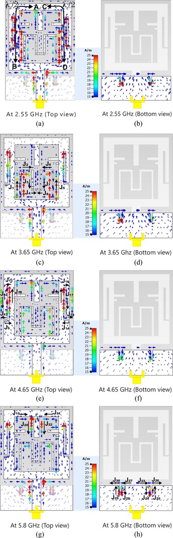
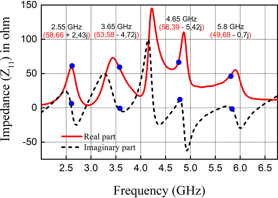
To examine more the operating mechanism of the presented antenna, namely Ant 3, the surface current density distribution on the patch surface (top view) and ground plane (bottom view) of the proposed antenna is simulated at 2.55, 3.65, 4.65, and 5.8 GHz resonant frequencies as shown in Fig. 4. It can be seen that, at the first resonant frequency, the surface current density is mostly concentrated in the inner vertical metallic strips of the square-ring patch along with the double inverted L-shaped DMS units. At the second resonant frequency, the surface current density is mainly focused near the meander-line parasitic structure (J 1 − J 4, and J 5 − J 8). At the third resonant frequency, the current density is more concentrated in the double inverted L-shaped DMS units (J 9 − J 13, and J 14 − J 18) having an electrical length of 0.5λ4.65 GHz, formed by WL 3, and H 4, as indicated in Fig. 4(e). At the fourth resonant frequency, the current density is mainly focused in the stub (J 19 − J 20, and J 21 − J 22) along with the double rectangular-shaped DGS units (J 23 − J 26, and J 27 − J 30), as indicated in Figs 4(g) and 4(h), respectively. It can be noticed that it is difficult to isolate the exact areas responsible for the resonances, especially at the third and fourth frequencies, as the different elements interact with each other. The surface current density around the contours of a vertical stub is higher at 5.8 GHz, contributing to impedance matching around 5.8 GHz as observed from the reflection coefficient plot for step 4, shown in Fig. 3. The variations of the real and imaginary parts of the antenna input impedance Z 11 are shown in Fig. 5. From the figure, it can be concluded that the real and imaginary parts of Z 11 are close to 50 and 0 Ω, respectively, over the four resonant frequency bands, which gives a good impedance matching and confirms the result in Fig 3.
Surface current distribution on the radiating patch and modified ground plane of the proposed antenna at 2.55, 3.65, 4.65, and 5.8 GHz resonant frequencies.

Variations of the real and imaginary parts of the antenna input impedance Z 11.

Parametric studies
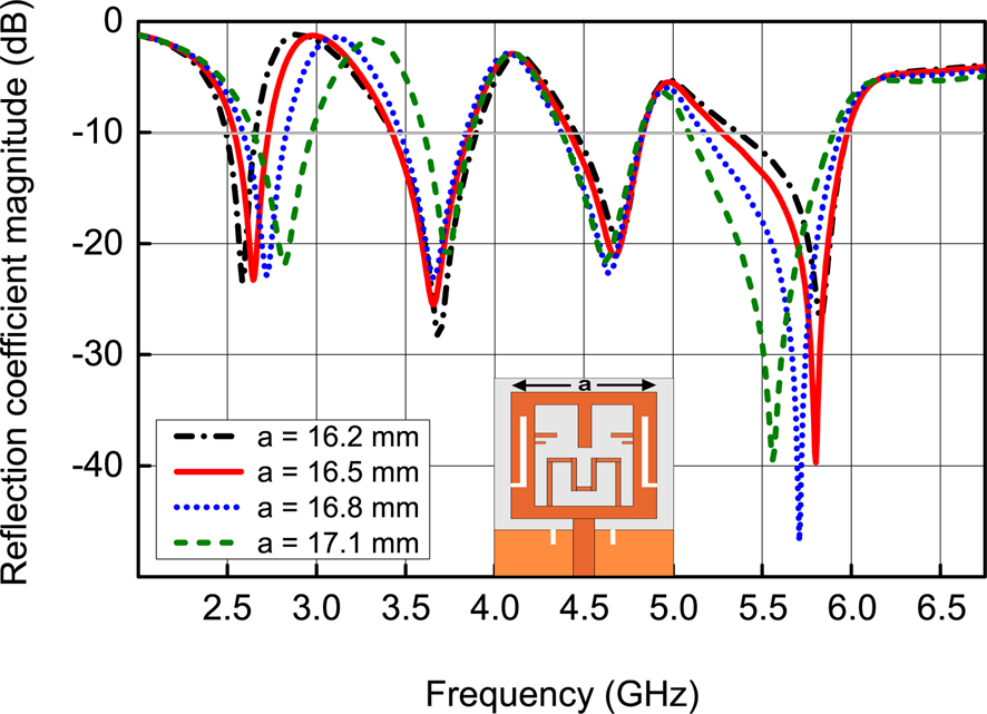
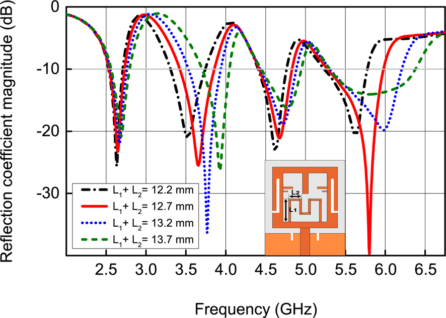
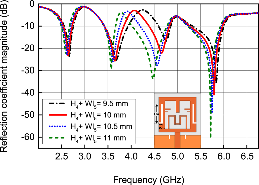
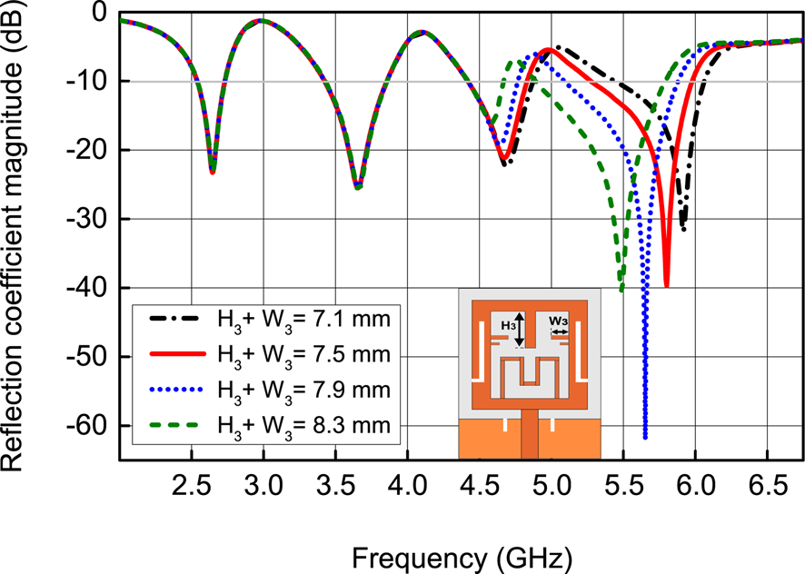
In order to ensure that the proposed antenna performance could meet the desired bands, parametric studies are carried out in this section. The effect of varying the width of square-ring “a”, length of the meander line (L 1 + L 2), length of L-shaped slot (H 4 + Wl 5), and length of a shorting oblique stub H 3 and width W 3 are investigated as shown in Figs 6–9, respectively.
Effect of varying the square-ring width a.

Effect of varying the meander-line length L 1 + L 2.

Effect of varying the L-shaped slot length.

Effect of varying the length of the open stubs.

Effect of varying the square-ring width a
The effect of the width “a” is investigated, while the other parameters are kept constant as shown in Fig. 6. The simulation is carried out for “a” values of 16.2, 16.5, 16.8, and 17.1 mm. Figure 6 shows that the 2.55 and 5.8 GHz resonant frequencies depend on the parameter “a”. The variation in the value of (a) from 16.2 to 17.1 mm lead to shift up the lower resonance frequency from 2.55 to 2.8 GHz. Main while, it shift down of the upper resonance frequency from 5.8 to 5.51 GHz.
Influence of the variation of the meander-line length
Figure 7 demonstrates the effect on the reflection coefficient when the parameter (L 1 + L 2) is varied from 12.2 to 13.7 mm. An increase in length (L 1 + L 2)of the meander line leads to shift up of the resonant frequencies (except the first one).
Varying the L-shaped slot length
Similarly, the influence of the L-shaped slot length (H 4 + Wl 5) on the reflection coefficient is given in Fig. 8. It can be seen from the figure below that as the length (H 4 + Wl 5) increases, the reflection coefficient at the frequency 4.65 GHz shifts toward the lower frequency side. Hence, a value of 10 mm for sub-6 GHz 5G frequency bands (n79) is considered to get the third resonant frequency at 4.65 GHz.
Effect of varying the open stubs lengths
Figure 9 shows the antenna return loss |S 11| for different values of length (H 3 + W 3). The increase in the length of the stubs leads to shifting of the third and fourth resonant frequencies to lower frequencies, while the first and second resonant frequencies are kept unchanged, a value of 7.5 mm is considered.
Fabrication and measurements
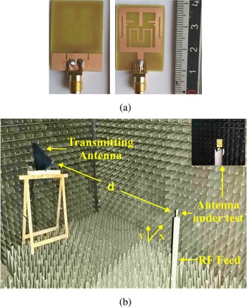
A prototype of the designed antenna was fabricated and tested to validate the proposed design. A photograph of the fabricated structure is shown in Fig. 10(a). The S parameters were measured using a vector network analyzer ZNB20. The far-field radiation patterns of the principal planes (E and H) were measured in a fully equipped anechoic chamber as shown in Fig. 10(b), where the commercial Logarithmic Periodic Antenna (HyperLOG 30180) is used as a reference antenna, at output power of 10 mW (10 dBm). The distance between the transmitting and receiving antennas is d = 1 m.
Fabricated antenna and measurement setup. (a) Photograph of the proposed antenna, and (b) antenna measurement in an anechoic chamber.

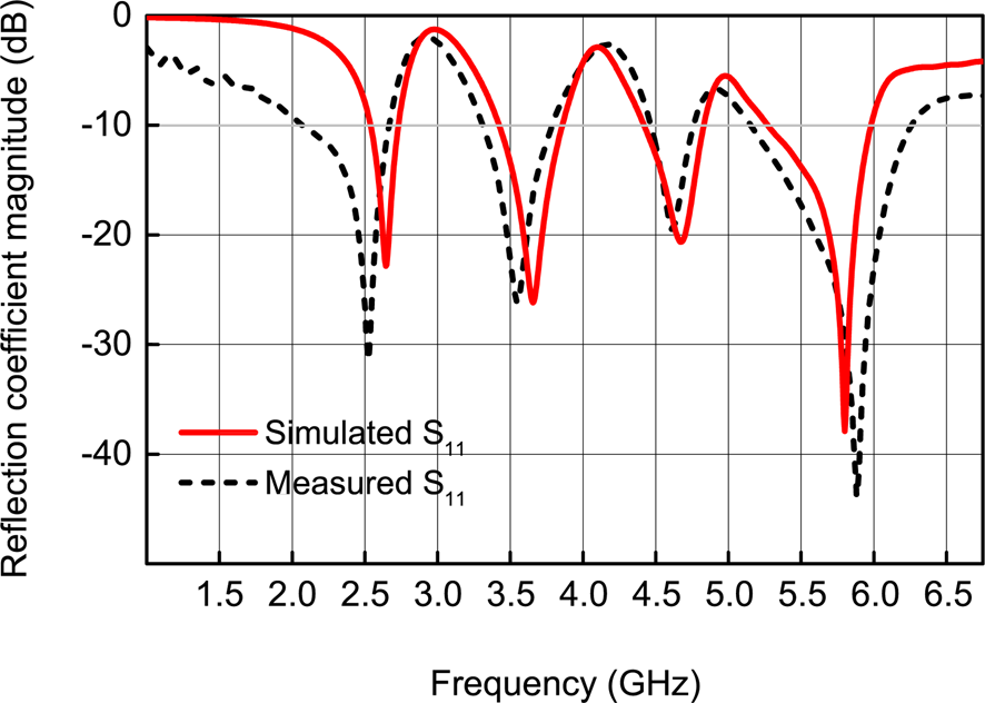
The obtained measured results are compared to the simulation ones as indicated in Fig. 11. This figure clearly confirms the quad-band behavior of the proposed antenna [2.52–2.75 GHz], [3.39–3.87 GHz], [4.4–4.86 GHz], and [5.2–6 GHz] covering the 5G sub-6 GHz (n78/n79) at (3.65/4.65 GHz), and LTE bands (B7/B46) at (2.55/5.8 GHz). Moreover, the two compared results present an acceptable agreement; however, the insignificant disagreement is due to errors in the fabrication and measurement apparatus.
Simulated and measured reflection coefficient magnitude of the proposed antenna.

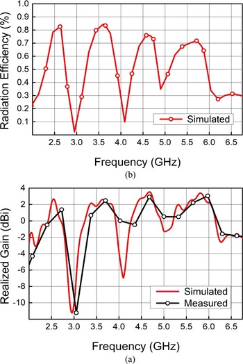
The simulated and measured realized gains are shown in Fig. 12(a) where the simulated radiation efficiency is depicted in Fig. 12(b). The antenna's realized gain is 2.1, 3.15, 3.35, and 3.75 dBi in the first, second, third, and fourth bands, respectively. The radiation efficiency is about 82, 85, 76, and 73% in the first, second, third, and fourth bands, respectively.
Antenna's performance in terms of (a) realized gain, and (b) radiation efficiency.

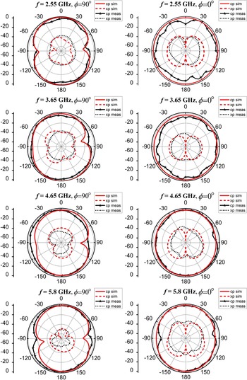
Figure 13 shows the simulated and measured 2D radiation patterns in two principal planes – namely, the E − (xz) and H − (xy) planes for four resonant frequencies of 2.55, 3.65, 4.65, and 5.8 GHz. At lower frequencies, the antenna exhibits omni-directional patterns for H-plane and a donut shape for E-plane with a low cross-polarization field and patterns are about the same as that of a typical monopole antenna. Polarization purity can only be seen at low frequencies where the cross-to-co polarization ratio is around − 35 dB, in contrast to higher frequencies, where the cross-polarization is dominant especially in H-plane. About 25–40 dB isolation between co-polarized and XP radiations is achieved with the proposed structure.
Simulated and measured radiation patterns of E- and H-planes at 2.55, 3.65, 4.65, and 5.8 GHz (xp, cross-polarization; cp, co-polarization).

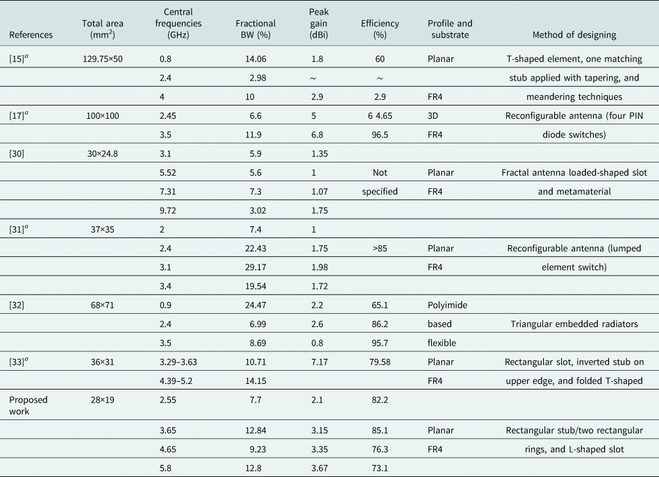
Table 3 illustrates a comparison between the proposed structure and recently reported antennas. From this table, the presented antenna is more compact than those described in [Reference Sekeljic, Yao and Hsu15, Reference Jin, Deng, Yang, Xu and Liao17, Reference Ali, Aw and Biradar30–Reference Ishteyaq, Masoodi and Muzaffar33] while having wider operating bandwidth adequate to cover all the sub-6 GHz 5G bands. Even though some reported designs achieved high gain and high efficiency, their large size and complex structure limit their applications in portable communications devices [Reference Jin, Deng, Yang, Xu and Liao17] and [Reference Xu, Chen, Zhao, Liu and Zhu32]. Moreover, the antennas reported in [Reference Ali, Aw and Biradar30] and [Reference Xu, Chen, Zhao, Liu and Zhu32] did not cover the all-sub-6 GHz bands. Accordingly, these attractive characteristics make the proposed antenna suitable for LTE and 5G sub-6 GHz communication applications.
Performance comparison with recently published works

aOnly sub-6 GHz band is considered for comparison.
Conclusion
In this paper, a new compact and miniaturized multi-band planar monopole antenna has been designed, fabricated, and tested. The obtained results in simulation and measurement show a behavior of quad-band and better impedance matching. The presented antenna with compact size of (0.24λ0 × 0.17λ0 × 0.013λ0) covers LTE B7 (2.52–2.75 GHz), Sub-6 GHz 5G (n77) (3.39–3.87 GHz), Sub-6 GHz 5G (n78) (4.4–4.86 GHz), and LTE B46 (5.1–5.82 GHz), while it has high radiation efficiency and moderately stable radiation patterns. The proposed quadband antenna operates in all the frequency bands of mobile telecommunication standards 4G (B7/B46), and 5G (n77/n78), and other applications, including WLAN and WiMAX.
Acknowledgements
The authors thank the Dean of the Faculty of Electric Engineering, University of Science and Technology–Houari Boumediene, Algiers and Anechoic laboratory staff of that Faculty.
Conflict of interest
The authors declare that they have no known competing financial interests or personal relationships that could have appeared to influence the work reported in this paper.
 Tarek Maamria received the M.Sc. (Magister) degree in electrical engineering from Polytechnic Military School, Algiers, Algeria, in 2016. Currently, he is a Ph.D. student in the Ecole Militaire Polytechnique of Algiers and his research interests include antenna and RF design, wireless sensors, IoT, and radar cross-section (RCS) of antennas.
 Mouloud Challal (M’09–SM’16) received the M.Sc. (Magister) and Doctorate degrees in Telecommunications from National Polytechnic School Algiers and Institute of Electrical and Electronic Engineering (IGEE, ex. INELEC), University M'Hamed BOUGARA Boumerdes (UMBB), ALGERIA, in 2001 and 2012, respectively. He is currently a full professor in the Telecommunications research group, Department of Electronics, and communication systems team leader in the Signals and Systems research Laboratory, IGEE/UMBB; ALGERIA. He handled a lot of responsibilities as Deputy Head of Electronics Department, from 2007 to 2008, Responsible of Master degree program in Telecommunications from 2013 to 2017, Vice-director in charge of studies and students’ related issues from 2017 to 2018 and as Director of the IGEE from 2018 to 2021. He was a founding member of the IEEE Algeria Sub-section where he held the post, as a volunteer, of treasurer from 2012 until 2014. He is also among active elements in the creation of both “IEEE Algeria Section” and “Association Algérienne de Génie Électrique et Électronique (AAGEE)”. He has authored/co-authored over 95 scientific papers. His current research interests include antennas and RF/microwaves circuits analysis, design and measurement.
 Fateh Benmahmoud received the Ing. and M.Sc.A. degrees in electrical engineering from Polytechnic Military School, Algiers, Algeria, in 2015, and the Doctor degree in Optics and Radiofrequencies from the University of Grenoble Alpes, France, in 2020. He participated as jury examiner/opponent for several Master and engineering degree defenses and authored and co-authored over 13 journal papers, letters, or international conferences. Currently, his activity includes antenna systems, wireless sensors, IoT, and signal processing.
 Khelil Fertas received the M.Sc. (Magister) and Doctorate degrees in electrical engineering from Polytechnic Military School, Algiers, Algeria and National Polytechnic School, Algiers, ALGERIA in 2014 and 2021, respectively. Currently, he is an assistant professor in the Material School at Algiers and a member of research team at Signals and Systems Laboratory, Institute of Electrical and Electronic Engineering (IGEE, ex. INELEC), University M'Hamed BOUGARA Boumerdes, ALGERIA. His fields of interest include optimization, RF passive and active circuits, DGS behaviors, propagation, and antennas.
 Ammar Mesloub received Engineer and Master degree in telecommunications from Polytechnic Military School, Algiers, Algeria, in 2006 and 2009 respectively. He received the Ph.D. in signal processing from EMP. He is an associate professor in Signal Processing Laboratory. His research interests are in signal processing, time-frequency analysis, and time-frequency array signal processing with applications in radar and communications.