I. INTRODUCTION
Severe plastic deformation (SPD) techniques, such as ultrasonic impact treatment (UIT), have been shown to produce fine grain microstructures and alter the material's properties without changing the chemical composition of metal alloys. Reference Gubicza, Chinh, Csanádi, Langdon and Ungár1–Reference Statnikov, Korolkov and Vityazev4 UIT is a handheld mechanical surface treatment similar to methods such as shot peening, laser shock peening, and deep rolling that is used to generate SPD in the subsurface layers of metals. UIT has been shown to lead to the formation of highly developed dislocation/grain microstructures and grain refinement. Reference An, Rodopoulos, Statnikov, Vitazev and Korolkov3 This causes compressive residual stresses and provides significant hardening in the material's surface layer, thereby increasing the material's resistance to fatigue, wear, and corrosion. Reference Liao, Chen and Bellinger5,Reference You-Li, Xie and Hong6
UIT involves the use of a pin tool that behaves like an ultrasonic transducer that outputs continuous ultrasonic impulse/vibrations at the output end of the tool to the treated surface. The technology is based on converting the ultrasonic oscillations of the transducer into impulses of ultrasonic impacts at the output. Reference An, Rodopoulos, Statnikov, Vitazev and Korolkov3–Reference Liao, Chen and Bellinger5 The output employs needle indenters, strengthened with hard materials such as carbide-containing alloys or artificial diamonds that are directed at the surface and are in continuous contact with the surface of the material. Reference An, Rodopoulos, Statnikov, Vitazev and Korolkov3–Reference Liao, Chen and Bellinger5 The continuous ultrasonic impact creates high rate straining and heating near the material surface resulting in SPD. The high rate straining generates energetically stable dislocation cells in aluminum resulting in stable compressive residual stresses.
SPD techniques such as UIT, ultrasonic shot peening (USSP), equal channel angular pressing (ECAP), and high-pressure torsion (HPT) have also been shown to form nanograins in aluminum alloys. Reference An, Rodopoulos, Statnikov, Vitazev and Korolkov3,Reference Sato, Tsuji, Minamino and Koizumi7–Reference Liu, Roven, Liu, Murashkin, Valiev, Ungár and Balogh12 The nanocrystalline layer is near surface with subgrains observed at regions of various depths below the surface. In 2024-T351, nanograins ranging in size from 8 to 15 nm were observed from the top surface to a depth of 5 µm from the surface when treated by the UIT process. Reference An, Rodopoulos, Statnikov, Vitazev and Korolkov3 Work by X. Wu demonstrated that USSP can induce ultrafine grain structures in aluminum 7075. Reference Wu, Tao, Hong, Xu, Lu and Lu13 Similar to UIT, USSP involves the use of a shot transferred to the component by means of a high frequency ultrasonic wave inside of a chamber.
In this work, sensitized aluminum–magnesium (Al–Mg) 5456-H116 removed from an in-service ship was subjected to UIT. Al–Mg alloys are nonheat-treatable binary alloys that derive their strength from solid solution strengthening and strain hardening. 5456 is an Al–Mg alloy that contains 4.7 to 5.5 wt% Mg. 14 Al–Mg alloys containing more than 3 wt% magnesium are susceptible to sensitization when exposed to elevated temperatures (>50 °C) for a prolonged period of time. Reference Oguocha, Adigun and Yannacopoulos15–Reference Davenport, Yuan, Ambat, Connolly, Strangwood, Afseth and Scamans17 Sensitization results from the formation of a continuous network of β-phase (Al3Mg2), at the grain boundaries. Reference Oguocha, Adigun and Yannacopoulos15–Reference Davenport, Yuan, Ambat, Connolly, Strangwood, Afseth and Scamans17 The β-phase is anodic to the adjacent metal matrix thus the grain boundaries become highly susceptible to stress corrosion cracking (SCC) and intergranular corrosion cracking (IGC). For SCC to occur, three elements are required: susceptible microstructure, corrosive environment, and a tensile stress. When one of these elements is eliminated, SCC may be mitigated. For this work, UIT was used to treat sensitized material to improve the material's resistance to SCC through grain modification and impartation of compressive stresses.
Previous work showed that UIT results in grain refinement and the formation of submicrometer grains near the surface to a depth of ∼10 µm. Reference Tran and Salamanca-Riba18 The submicrometer grains have an average size of 100–400 nm in diameter with some plastically deformed areas showing small nanograins that are on the order of 2–6 nm. Reference Tran and Salamanca-Riba18 The inhomogeneity in the grain structure may be due to the random nature of the UIT process, a handheld manual process, which results in random deformation at the surface. The objective of the work reported herein was to examine the kinetics of grain growth in the submicrometer grains microstructure using in situ elevated temperature TEM.
In severely plastically deformed Al–Mg alloys, authors have reported that significant grain growth does not occur until ∼300 °C. Z. Horita et al. reported that subsequent annealing of 5083 processed by ECAP at various temperatures for one hour did not result in significant grain growth up to 300 °C. Reference Horita, Funjinami, Nemoto and Langdon11 The microstructure after annealing at 100 °C was essentially identical to the microstructure following ECAP processing in which the grains had an average size of less than 1 µm. Reference Horita, Funjinami, Nemoto and Langdon11 Annealing at 200 °C reduced the dislocation density within the grain; however there was little or no grain growth. At 300 °C, significant grain growth was observed and the microstructure consisted of grains that exceeded 1.0 µm. In a similar study, D.G. Morris and M.A. Munoz-Morris found grain growth to occur in ECAP processed Al–3Mg following a one hour anneal at 250 °C. Reference Morris and Munoz-Morris19 The ECAP microstructure before annealing consisted of elongated grains measuring 0.1 µm wide by 1.0–1.2 µm in length. Annealing for one hour at 250 °C resulted in a duplex microstructure consisting of bands of slightly coarsened grains and regions of coarser grains of 5–10 µm. Annealing at 250 °C for 5–15 min led to a slightly coarsened microstructure with near equiaxed grains.
II. EXPERIMENTAL
The material used for this work was sensitized in-service 5456-H116 plate with a chemical composition containing (wt%) 0.16 Si, 0.19 Fe, 0.061 Cu, 0.67 Mn, 4.6 Mg (slightly below specification minimum), 0.073 Cr, 0.063 Zn, 0.014 Ti. 14 The sensitization level of the material was determined by ASTM G67 Standard Test Method for Determining the Susceptibility to Intergranular Corrosion for 5XXX Aluminum Alloys by Mass Loss After Exposure to Nitric Acid (NAMLT Test). 20 The sensitization level was found to be ∼60 mg/cm2 which is considered severely sensitized. In accordance with ASTM G67, a mass loss greater than 25 mg/cm2 is considered sensitized. The plate was treated by UIT using Esonix equipment (Birmingham, AL) consisting of an indenter with four pins, each with a pin tip radius of 3 mm. The equipment was operated at a frequency of 27 kHz and with electrical parameters of 80 volts and 11.2 amps. The treatment amplitude was 22 μm and the average travel speed was 10 cm/min.
Planar slices of ∼0.5 mm in thickness were obtained from a 15 mm × 15 mm sample that was sectioned from a large plate treated with UIT. The planar slices were mechanically polished on the underside of the UIT surface to preserve the treated surface. Three-millimeter discs for TEM were punched from the planar slices. TEM foils were prepared by mechanical polishing with 30-µm diamond paper, followed by electropolishing in 25% HNO3 in CH3OH, and lastly polished with low (1–5) kV in a Fischione 1010 ion mill (Export, PA). The samples were prepared by polishing and ion milling only on the underside of the UIT surface. In situ elevated temperature TEM analysis using a heating stage was performed with a Gatan heating holder and Smart Heater controller in a transmission electron microscope (TEM; model JEOL 2100 LaB6, Akishima, Tokyo). The experiments were conducted at a 200 kV operating voltage.
Two experiments were conducted in situ. The first experiment involved heating the sample from room temperature to 50 °C followed by heating to a maximum temperature of 450 °C in increments of 50 °C. The experimental heating rate for both experiments was 1000 °C/min. The sample was held for 10 min at each temperature. After heating to 450 °C, the samples were cooled to room temperature. A second sample was heated from room temperature to 100, 200, 300, 350, 400, and 450 °C. The samples were held at each temperature for 10 min between 100 and 400 °C. The sample was then held for 40 min at 450 °C to investigate the grain growth at that temperature. Dark-field (DF) imaging was captured with a high resolution Orius 1000 charge-coupled device (CCD) camera (Warrendale, PA). The radius of the objective used for DF imaging was 5/nm and included a few spots from several submicron grains as well as a segment of the ring at ∼7/nm.
III. RESULTS
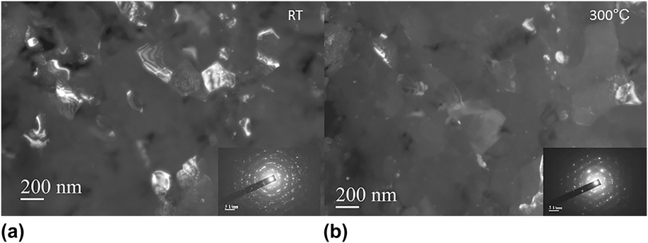
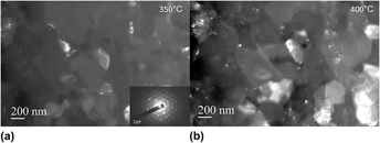
Figures 1–4 obtained from the first experiment show DF micrographs that represent the changes in the grain structure from room temperature to 450 °C along with the associated diffraction patterns obtained at room temperature, 300, 350, and 450 °C. At room temperature, the microstructure includes nanograins and submicrometer grains as previously reported by Tran and Salamanca-Riba. Reference Tran and Salamanca-Riba18 From the micrograph obtained at room temperature, Fig. 1, the submicrometer grains range in size from 100 to 300 nm with a number of grains that are an average of ∼200 nm. Heating between room temperature and 250 °C resulted in no grain growth but rather changes in grain orientation due to thermal expansion and sample bending. Diffraction patterns were not obtained at 100, 150, and 250 °C since no appreciable grain growth was observed at these temperatures. Upon heating the sample to 300 °C, Fig. 1, grain growth starts to occur and the submicrometer grains start to grow in size. Between 350 and 450 °C, significant grain growth occurs with some grains becoming as large as 600 nm. Although significant grain growth occurs at 400 °C, Fig. 2, the microstructure exhibits some submicrometer grains which are still present even upon heating to 450 °C, Fig. 3.
(a) DF TEM micrographs of UIT 5456 at room temperature (RT) showing the presence of submicrometer grains and (b) grain growth at 300 °C. The insets in the bottom right are the diffraction pattern from the areas.

DF TEM micrographs of UIT 5456 at 350 and 400 °C showing the presence of submicrometer grains and grain growth. The inset at the bottom of the left image is the diffraction pattern of the area and shows typical ring pattern characteristic of submicrometer grains with some strong spots indicating grain growth at 350 °C.

DF TEM micrographs of UIT 5456 (a) at 450 °C showing significant grain growth and (b) cooled to room temperature after heating to 450 °C showing stable grain growth. The insets at the bottom right of each figure are the diffraction patterns of the areas.

DF images of UIT 5456 heated to 450 °C and held for various lengths of time following significant grain growth; holding for 40 min did not result in further grain growth.

As the grain structure changes, the diffraction pattern changes from distinct broad ring patterns typical of a submicrometer grain structure to diffraction patterns with stronger and sharper spots indicating grain growth from 300 to 450 °C, Figs. 1–3. Weak ring patterns are still visible at 300 °C, Fig. 1, and even at 450 °C, Fig. 3, confirming the presence of small random grains. The DF image at 450 °C, Fig. 3, shows a number of small white spots that appear to be precipitates within each individual grain and at the grain boundaries. The precipitates started to form upon heating to 300 °C and were more pronounced with increasing temperature to 450 °C. Figure 3 shows that the grain growth remains stable after cooling to room temperature from 450 °C.
The results from a second heating experiment were consistent with the results of the first heating experiment. Grain growth began when the sample was heated above 300 °C. Holding at each temperature for 10 min did not result in any significant changes in the growth rate or grain sizes. A number of small precipitates were observed in the microstructure which is consistent with the observations in the first experiment. Holding the sample for 40 min did not result in any observable changes in grain growth or significant increase in grain size once the sample was heated to 450 °C. Figure 4 shows the DF images after initial heating to 450° and holding at 450 °C for 15, 30, and 40 min.
The activation energy for grain growth can be determined by the relationship between the average final grain size (d) and initial average grain size (d 0): Reference Wang, Iwahashi, Horita, Furukawa, Nemoto, Valiev and Langdon21,Reference Reed-Hill and Abbaschian22
 $$d^{2} - d_0^2 = k_{\rm{g}} t^n \quad {\rm{,}}$$
where t is time, n is a constant usually taken as unity. k g is a temperature-dependent constant given by:
 $$k_{\rm{g}} = A\exp \left( { - {\raise0.7ex\hbox{$Q$} \!\mathord{\left/ {\vphantom {Q {RT}}}\right.\kern-\nulldelimiterspace}\!\lower0.7ex\hbox{${RT}$}}} \right)\quad {\rm{,}}$$
where Q is the activation energy for grain growth, R is the gas constant, T is the absolute temperature, and A is a constant. Grain growth can be then written as follows:
 $$d^2 - d_0^2 = At^n {\mathop{\rm e}\nolimits} ^{ - {\raise0.7ex\hbox{$Q$} \!\mathord{\left/ {\vphantom {Q {RT}}}\right.\kern-\nulldelimiterspace}\!\lower0.7ex\hbox{${RT}$}}} \quad {\rm{.}}$$
Rearranging Eq. (3) and taking the log of both sides gives the following expression: Reference Wang, Iwahashi, Horita, Furukawa, Nemoto, Valiev and Langdon21,Reference Reed-Hill and Abbaschian22
 $$\log {{d^2 - d_0^2 } \over {t^n }} = - {Q \over {2.3RT}} + \log A\quad {\rm{.}}$$
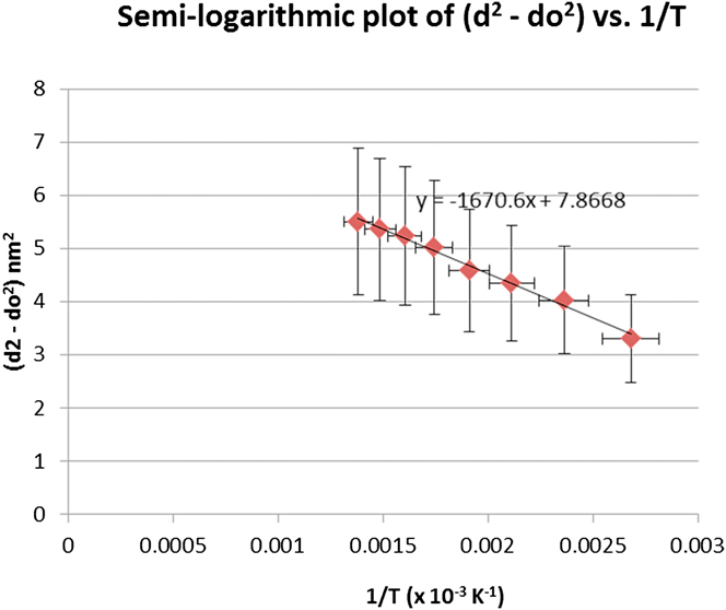
The average grain size diameters as determined from the TEM micrographs were used to construct the semilogarithmic plot (d 2 − d 0 2) versus 1/T in Fig. 5. Average grain size determination was accomplished by identifying and measuring for each temperature condition, at least 10 grains with well-defined grain boundaries. The initial diameter, d 0, is the average grain size diameter at room temperature which is 200 ± 50 nm. From the plot, the slope of the curve, m = −1671, is used to calculate the activation energy, Q, where R = 8.314 J/(mol K):
 $$Q = 2.3(8.314\,{\rm{J}}/({\rm{mol K)}})(1671) = 31,953\,{\rm{J}}/{\rm{mol}}\;{\rm{or}}\;\sim32\,{\rm{kJ}}/{\rm{mol}}\quad .$$
Semilogarithmic plot of (d 2 − d 0 2) versus 1/T for grain growth from in situ heating TEM of UIT material; Slope of the line is Q/2.3R.

Therefore, the activation energy required for grain growth in the UIT material is ∼32 kJ/mol.
IV. DISCUSSION
The results of the in situ TEM heating experiments demonstrate that the submicrometer grains in severely plastically deformed Al–Mg are stable to approximately 300 °C. Annealing above 300 °C results in grain growth and a microstructure with both submicrometer grains and random nanograins that are less than 100 nm. Significant grain growth occurs at 400 °C as shown in Fig. 2. Heating to 450 °C resulted in additional grain growth as shown in Fig. 3; however, holding at 450 °C for a prolonged period of time did not significantly increase the grain growth or growth rate, Fig. 4. It is noted that grain growth may be influenced by TEM foil thickness; for the in situ TEM heating experiments the growth rate for grains >∼500 nm would be influenced by the foil surface and limited by the sample thickness which is estimated to be around 500 nm in the areas investigated. These results agree with the findings by Z. Horita et al. who reported that subsequent annealing of 5083 processed by ECAP at various temperatures for one hour did not result in significant grain growth until 300 °C. Reference Horita, Funjinami, Nemoto and Langdon11
The observed grain growth in the present work is consistent with previous results on the microstructural evolution of heavily deformed Al–Mg by ECAP subject to subsequent annealing. Reference Horita, Funjinami, Nemoto and Langdon11,Reference Morris and Munoz-Morris19 Processes such as UIT impart high levels of straining into the surface layer resulting in a deformed microstructure with refined submicron grains and high dislocation density. Reference An, Rodopoulos, Statnikov, Vitazev and Korolkov3,Reference Wu, Tao, Hong, Xu, Lu and Lu13,Reference Tran and Salamanca-Riba18 Annealing of deformed Al–Mg at lower temperatures between 150 and 250 °C results in dislocation recovery and reduction in dislocation density at the grain boundaries and within the grains. Reference Horita, Funjinami, Nemoto and Langdon11,Reference Morris and Munoz-Morris19 The dislocations arrange to form subboundaries and more clearly defined grain boundaries. Reference Horita, Funjinami, Nemoto and Langdon11,Reference Morris and Munoz-Morris19 D.G. Morris and M.A. Munoz-Morris reported that the grain size also increased due to grain coarsening simultaneously resulting in a duplex microstructure. At higher temperatures above 250 °C, a second recrystallization process occurs in which submicron grains are replaced by larger grains of 5–10 µm size. Reference Morris and Munoz-Morris19 Z. Horita et al. reported no significant grain growth at 200 °C but rather at 300 °C. Reference Horita, Funjinami, Nemoto and Langdon11
The in situ heating stage TEM experiments presented here indicate that the recrystallization temperature for UIT 5456 is 300 °C which agrees with the work reported by Z. Hortia et al. for 5083 processed by ECAP. Reference Horita, Funjinami, Nemoto and Langdon11 Plastically or heavily deformed metals may undergo recrystallization upon annealing where the driving force for recrystallization is the strain energy stored in the deformed microstructure. Reference Godiksen, Schmidt and Jensen23 The boundaries surrounding the recrystallizing grains migrate through the deformed material impinging upon other recrystallizing grains which may transform the entire deformed microstructure into a fully recrystallized polycrystalline grain structure. Reference Godiksen, Schmidt and Jensen23 In heavily deformed Al–Mg, the driving force for recrystallization is high. Reference Koizumi, Kohara and Inagaki24,Reference Ryum and Embury25 In aluminum alloys, the recrystallization temperature has also been found to be influenced by the addition of Mg. Reference Koizumi, Kohara and Inagaki24,Reference Ryum and Embury25 M. Koizumi et al. found that in Al–Mg with various contents of Mg cold rolled to 95% reduction and annealed at temperatures between 200 and 450 °C, the Mg content strongly influences the recrystallization temperature and rate. Reference Koizumi, Kohara and Inagaki24 At 1.0 wt% Mg, recrystallization is retarded; however with increasing Mg content above 2 wt%, recrystallization was accelerated and occurs at a lower temperature. For Al–5Mg, 100% recrystallization was found to occur at ∼300 °C following annealing treatments for 5 min at 225, 250, 275, and 300 °C. At high Mg solute concentrations, the rate of recrystallization becomes constant and at very high Mg concentrations where the solubility limit is exceeded, secondary phase particles are precipitated. In 80% cold rolled Al–5Mg annealed for one hour between 260 and 350 °C, N. Ryum and J.D. Embury reported that Mg serves to reduce both the growth rate and final grain size and gives greater nonuniformity in the scale of the recrystallized structure. Reference Dai, Villegas and Shaw2
Research by J. Wang et al. reports different activation energies for grain growth to fully recrystallized and to unrecrystallized grains in an Al–3Mg with an initial submicrometer grain structure of ∼0.2 µm produced by ECAP and subsequently annealed at various temperatures. Reference Wang, Iwahashi, Horita, Furukawa, Nemoto, Valiev and Langdon21 Annealing heat treatments were performed at constant temperature in the range from 443 to 548 K (170–275 °C) in silicon oil or 563 to 803 K (290–530 °C) in an Ar atmosphere furnace for 1 h. Reference Wang, Iwahashi, Horita, Furukawa, Nemoto, Valiev and Langdon21 Significant grain growth occurred at 503 K (230 °C) resulting in a duplex microstructure consisting of unrecrystallized grains with nonequilibrium grain boundaries and recrystallized grains. Reference Wang, Iwahashi, Horita, Furukawa, Nemoto, Valiev and Langdon21 The material was fully recrystallized at 563 K (290 °C) with grains greater than 100 µm in diameter. Reference Wang, Iwahashi, Horita, Furukawa, Nemoto, Valiev and Langdon21 The activation energy for grain growth to a fully recrystallized structure was determined to be ∼90 kJ/mol which is consistent with the activation energy required for grain boundary diffusion in aluminum, ∼86 kJ/mol. For the unrecrystallized grains, the activation energy is ∼30 kJ/mol. Reference Wang, Iwahashi, Horita, Furukawa, Nemoto, Valiev and Langdon21
The grain growth activation energy calculated from the in situ elevated temperature experiments for the UIT material in the current work, ∼32 kJ/mol, is very low when compared with the activation energy for fully recrystallized grains reported by J. Wang et al. Reference Wang, Iwahashi, Horita, Furukawa, Nemoto, Valiev and Langdon21 However, the activation energy agrees with the findings by J. Wang et al. for unrecrystallized grains of ∼30 kJ/mol. Reference Wang, Iwahashi, Horita, Furukawa, Nemoto, Valiev and Langdon21 In a related study, M. Furukawa et al. reported an activation energy of ∼25 kJ/mol for unrecrystallized grain growth of Al–3Mg with initial grain size of 0.09 µm produced by torsional straining and subsequently annealed between 323 and 793 K (50–520 °C). Reference Furukawa, Horita, Nemoto, Valiev and Langdon26 The activation energy is of the order of 0.2Q i where Q i is the activation energy for self-diffusion in pure aluminum. Reference Furukawa, Horita, Nemoto, Valiev and Langdon26 M. Furukawa et al. stated that the low activation is consistent with the high atomic mobility anticipated in nonequilibrium grain boundaries and is a consequence of the significant distortion and excess dislocations. Reference Furukawa, Horita, Nemoto, Valiev and Langdon26 The in situ TEM experiments in the present work resulted in a duplex microstructure indicating that the microstructure was not fully recrystallized. The results also agree with the concept of a low activation energy for grain diffusion in ultrafine grain materials because of the nonequilibrium grain boundaries which are characteristic of submicrometer grains. Reference Liu, Roven, Murashkin and Valiev27,Reference Horita, Smith, Furukawa, Nemoto, Valiev and Langdon28 Previous work has shown that the UIT process results in grain boundaries that are curved or wavy which suggest that the grain boundaries are in a high-energy nonequilibrium state. Reference Tran and Salamanca-Riba18
M. Kubota reported the formation of plate and lath-shaped precipitate particles during the early stages of aging of Al–10Mg alloy aged at 200 °C. Reference Kubota29 The plate-like precipitates were identified as β′ phase or the metastable intermediate phase with a similar composition to the equilibrium β phase. Reference Kubota29 The in situ heating experiments in the present work resulted in the formation of fine precipitates upon heating at 300 °C, however it is unclear as to whether these precipitates are intermediate β′ phase. Therefore additional TEM analysis is required.
V. SUMMARY
In situ elevated temperature TEM analysis shows that the submicrometer grains formed by the UIT process in sensitized Al–Mg 5456-H116 are thermally stable up to ∼300 °C. Grain growth starts to occur when the material is heated above 300 °C with significant grain growth occurring at ∼400 °C. The grains continue to grow upon heating to 450 °C; however, the grain size did not significantly increase when the temperature was held at 450 °C for a prolonged period of time. The in situ TEM experiments resulted in a duplex microstructure indicating that the microstructure was not fully recrystallized. The activation energy for grain growth was determined to be ∼32 kJ/mol which is low as compared with the activation energy for fully recrystallized grains in Al–Mg, however the activation energy agrees with the activation energy reported for unrecrystallized grains, ∼30 kJ/mol. Reference Wang, Iwahashi, Horita, Furukawa, Nemoto, Valiev and Langdon21 Upon heating to 300 °C, the formation of fine precipitates was observed and was more pronounced with increasing temperature to 450 °C. It is not clear whether these precipitates are intermediate β′ phase, therefore additional TEM analysis is required.
ACKNOWLEDGMENTS
This work was supported by the Office of Naval Research (Grant No. N000141010867, N000141210424) and Naval Surface Warfare Center Carderock Division (Grant No. N001671000168). The authors would like to acknowledge the support of the Maryland NanoCenter and Nanoscale Imaging, Spectroscopy, and Properties Laboratory (NISP Lab). The NISP Lab is supported by the National Science Foundation as a Materials Research Science and Engineering Center Shared Experimental Facility.