





1. Introduction
Vitaly Dmitrievich Shafranov noted that toroidal plasmas in magnetohydrodynamic (MHD) equilibrium have the tendency to move into regions of weaker magnetic field when the pressure is increased. He calculated the resulting shift of the magnetic surfaces in a large-aspect-ratio tokamak with circular cross-section (Shafranov Reference Shafranov1958, Reference Shafranov1966) – a calculation that is reproduced in most textbooks on fusion plasma physics. He also calculated the corresponding shift in a stellarator with almost circular cross-section (Shafranov Reference Shafranov1966; Solovev & Shafranov Reference Solovev and Shafranov1970), but most stellarators are strongly shaped and this circumstance can make the Shafranov shift quite different.
The Shafranov shift is of considerable practical importance in stellarators, because it sets a limit on the achievable pressure – an MHD equilibrium limit rather than a stability limit. At high enough beta (thermal pressure divided by magnetic energy density), the Shafranov shift is comparable to the minor radius of the plasma, causing the latter to be pushed against the outer boundary and a magnetic separatrix to form that limits the confinement volume. Alternatively, a region of chaotic field lines can appear in the periphery of the plasma, also reducing confinement volume (Drevlak, Monticello & Reiman Reference Drevlak, Monticello and Reiman2005; Loizu et al. Reference Loizu, Hudson, Nührenberg, Geiger and Helander2017). In addition to causing an MHD equilibrium limit, the Shafranov shift can greatly enhance neoclassical transport and fast-particle losses.
Spitzer (Reference Spitzer1958) estimated the pressure limit in a classical stellarator with circular cross-section to scale as
 \begin{align} \beta \sim \epsilon \iota ^2, \end{align}
where
 $\epsilon$
denotes the inverse aspect ratio and
 $\iota$
the rotational transform. Many other special cases have been calculated more carefully over the years (Pustovitov & Shafranov Reference Pustovitov and Shafranov1990), and it would be useful to understand the Shafranov shift in an arbitrarily shaped stellarator. However, there is no general analytical formula for it, and it is difficult to see how there could be one. With increasing pressure, each point on the magnetic axis is displaced in some direction and by some distance that both vary along the magnetic axis. Moreover, these quantities depend on the entire pressure profile and the boundary condition at the edge of the plasma. In the present article, instead of considering this level of detail, we introduce an average measure of the Shafranov shift and discuss its properties in various classes of magnetic configurations, particularly quasisymmetric and quasi-isodynamic (QI) ones. In order to make analytical progress, it is necessary to adopt the approximation of large aspect ratio, but the shape of the magnetic axis and the plasma cross-section are taken to be arbitrary. As a result, we are able to derive scalings and upper bounds on the Shafranov shift of more general nature than has earlier been possible.Footnote
1
2. Magnetic field and plasma current
2.1. General expressions
In this section, we recall general expressions for the magnetic field and plasma current in stellarators. Most of the results are well known and can be found in several places of the published literature, see e.g. the review by Helander (Reference Helander2014). The plasma is assumed to be in a scalar-pressure MHD equilibrium without flow, in which the magnetic-field lines trace out simply nested flux surfaces
 \begin{align} \boldsymbol {J} \times \boldsymbol {B} = \boldsymbol{\nabla }p, \end{align}
where
 $p$
denotes the pressure,
 $\boldsymbol {B}$
the magnetic field and
 $\boldsymbol {J}$
the current density. Boozer coordinates
 $(\psi ,\theta ,\varphi )$
can then be introduced and the magnetic field written as (Boozer Reference Boozer1981)
 \begin{align} \boldsymbol {B} = \boldsymbol{\nabla }\psi \times \boldsymbol{\nabla }\theta + \boldsymbol{\nabla }\varphi \times \boldsymbol{\nabla }\chi = G(\psi ) \boldsymbol{\nabla }\varphi + I(\psi ) \boldsymbol{\nabla }\theta + K(\psi ,\theta ,\varphi ) \boldsymbol{\nabla }\psi , \end{align}
where
 $\psi$
and
 $\chi$
measure toroidal and poloidal fluxes, respectively. The quantity
 $\psi$
is chosen to vanish on the magnetic axis, while
 $\chi$
is taken to vanish at the plasma edge and thus to attain its maximumFootnote
2
on the magnetic axis. The function
 $I(\psi )$
is proportional to the total toroidal current enclosed by the flux surface
 $\psi$
. In most stellarators
 $I(\psi )$
is much smaller than
 $G(\psi )$
, since the current in the toroidal-field coils is much larger than the toroidal plasma current. The derivative
 $G'(\psi )$
is proportional to the pressure gradient, making
 $G(\psi )$
almost constant in a low-beta plasma. The Jacobian is
 \begin{align} \frac {1}{\sqrt {g}} = (\boldsymbol{\nabla }\psi \times \boldsymbol{\nabla }\theta ) \boldsymbol{\cdot }\boldsymbol{\nabla }\varphi = \frac {B^2}{G + \iota I}, \end{align}
where
 $\iota (\psi ) = {\rm d} \chi / {\rm d} \psi$
denotes the rotational transform. We shall also use another set of coordinates
 $(\psi ,\alpha ,l)$
, where
 $\alpha = \theta - \iota (\psi ) \varphi$
labels the different field lines on each flux surface, and
 $l$
denotes the arc length along each field line.
The flux-surface average of a function
 $f(\psi ,\theta ,\varphi )$
is defined as the volume average of this function over the region between two neighbouring magnetic surfaces
 \begin{align} \left \langle f \right \rangle = \frac {1}{V'(\psi )} \int _0^{2\pi } {\rm d} \theta \int _0^{2\pi /N_p} f(\psi ,\theta ,\varphi ) \sqrt {g(\psi ,\theta ,\varphi )} \; {\rm d} \varphi , \end{align}
where
 \begin{align} V'(\psi ) = \int _0^{2\pi } {\rm d} \theta \int _0^{2\pi /N_p} \sqrt {g} \; {\rm d} \varphi \end{align}
denotes the volume enclosed by the surface labelled by
 $\psi$
in one period of the stellarator, whose shape is assumed to be invariant under toroidal rotation by the angle
 $2 \pi / N_p$
. Here,
 $N_p$
denotes the number of field periods.
Since the divergence of the diamagnetic current
 \begin{align} \boldsymbol {J}_\perp = \frac {\boldsymbol {B} \times \boldsymbol{\nabla }p}{B^2} \end{align}
in general does not vanish, already Spitzer (Reference Spitzer1958) noted that there must be a current along
 $\boldsymbol {B}$
satisfying
 \begin{align} \boldsymbol {B} \boldsymbol{\cdot }\boldsymbol{\nabla }\left (\frac {J_\|}{B} \right ) = - (\boldsymbol {B} \times \boldsymbol{\nabla }p) \boldsymbol{\cdot }\boldsymbol{\nabla }\left ( \frac {1}{ B^{2}} \right ). \end{align}
The Pfirsch–Schlüter current is defined as the part of this current that does not contribute to the net toroidal current, i.e.
 \begin{align} J_{\|}^{\textrm {PS}} = J_{\|} - \frac {\left \langle J_{\|} B \right \rangle B}{\langle B^2 \rangle }. \end{align}
In the absence of an ohmic current, the bootstrap current and auxilliary current drive,
 $J_{\|}^{\textrm {PS}} = J_{\|}$
. As Boozer first observed, the Pfirsch–Schlüter current can be expressed in terms of the Fourier coefficients of
 \begin{align} \frac {1}{B^2} = \sum _{m,n} h_{mn}(\psi ) e^{i(m \theta - n \varphi )}, \end{align}
as
 \begin{align} \frac {J_\|^{\textrm {PS}}}{B} = -\frac {{\rm d}\kern-1pt p}{{\rm d} \psi } \sum _{m,n\ne 0} \frac {nI + mG}{m \iota - n} h_{mn} e^{i(m \theta - n \varphi )}, \end{align}
where each coefficient
 $h_{mn}(\psi )$
vanishes on the resonant surface where
 $\iota (\psi )=n/m$
. Otherwise, a current singularity arises, which has recently been analysed in detail by Huang et al. (Reference Huang, Zhou, Loizu, Hudson and Bhattacharjee2023).
2.2. Quasisymmetric magnetic fields
Quasisymmetric fields are those for which the field strength only depends on a linear combination of the Boozer angles,
 $B = B(\psi ,\theta - N \varphi )$
, where the integer
 $N$
vanishes in quasi-axisymmetric stellarators and usually coincides with the number of field periods in quasihelically symmetric ones. For such fields, any function of the form
 $f(\psi ,B)$
satisfies
 \begin{align} \boldsymbol {B} \boldsymbol{\cdot }\boldsymbol{\nabla }f & = \frac {\iota - N}{\sqrt {g}} \left ( \frac {\partial f}{\partial \theta } \right )_{\psi ,\varphi }\!,\\[-7pt]\nonumber \end{align}
 \begin{align} (\boldsymbol {B} \times \boldsymbol{\nabla }\psi ) \boldsymbol{\cdot }\boldsymbol{\nabla }f & = \frac {G + NI}{\sqrt {g}} \left ( \frac {\partial f}{\partial \theta } \right )_{\psi ,\varphi }\!, \end{align}
and (2.7) reduces to an ordinary differential equation that can be solved analytically, giving
 \begin{align} J_{\|}^{\textrm {PS}} = \frac {G + NI}{N-\iota } \frac {{\rm d}\kern-1pt p}{{\rm d} \psi } \left ( \frac {1}{B} - \frac {B}{\langle B^2 \rangle } \right )\!. \end{align}
Note that, in a tokamak or a quasi-axisymmetric stellarator (
 $N = 0$
), the Pfirsch–Schlüter current is proportional to
 $G/\iota$
, whereas in a quasihelically symmetric stellarator without net current (
 $I = 0$
), it is instead proportional to
 $G/(N - \iota )$
. It is thus relatively small if the number of field periods is large.
2.3. QI magnetic fields
By definition, a QI magnetic field satisfies the following two conditions (Helander & Nührenberg Reference Helander and Nührenberg2009; Nührenberg Reference Nührenberg2010).
-
(i) On each flux surface, all contours of constant field strength have the same topology and form poloidally closed curves, rather than toroidally or helically closed ones.
-
(ii) For trapped particles, the distance along the field between consecutive bounce points depends on the field strength at these points and on the flux surface on which they reside, but is the same for all field lines on that surface. In other words, in the coordinates
 $(\psi ,\alpha ,l)$
introduced above, the arc length between two points,
$(\psi ,\alpha ,l_0)$
and
$(\psi ,\alpha ,l_1)$
, of equal field strength on the same field line depends on
$B(\psi ,\alpha ,l_0) = B(\psi ,\alpha ,l_1)$
and
$\psi$
but not on the Clebsch angle
$\alpha$
, provided that
$B(\psi ,\alpha ,l) \lt B(\psi ,\alpha ,l_0)$
for all
$l \in (l_0,l_1)$
. In particular, the distance between two consecutive field-strength maxima,(2.14)depends only on
\begin{align} L(\psi ) = \int _{B(\psi ,\alpha ,l) \leqslant B_{\textrm {max}}(\psi )} {\rm d}l, \end{align}
$\psi$
.


These conditions, which have been elaborated upon by Parra et al. (Reference Parra, Calvo, Helander and Landreman2015) and Helander et al. (Reference Helander, Goodman, Beidler, Kuczynski and Smith2024), guarantee that magnetically trapped particles, on a time average, drift in the poloidal direction rather than radially, toroidally or helically (Cary & Shasharina Reference Cary and Shasharina1997). They also ensure that, for any function
 $f\!(\psi ,B)$
,
 \begin{align} \frac {\partial }{\partial \alpha } \int _{B(\psi ,\alpha ,l)\lt B} f[\psi ,B(\psi ,\alpha ,l)] {\rm d}l = 0. \end{align}
It was observed by Subbotin et al. (Reference Subbotin2006) that this property has an important implication for the Pfirsch–Schlüter current in the important case that the net toroidal current vanishes,
 $I(\psi ) = 0$
, so that
 $\boldsymbol {B} = G \boldsymbol{\nabla }\varphi + K \boldsymbol{\nabla }\psi$
. In the coordinate system
 $(\psi ,\alpha , l)$
, the equation for the Pfirsch–Schlüter current (2.7) then becomes
 \begin{align} \frac {\partial u}{\partial l} = - 2 \; \frac {\partial }{\partial \alpha } \left ( \frac {1}{B} \right ), \end{align}
where
 $u(\psi ,\alpha ,l) = J_\| / [p'(\psi ) B]$
. If we integrate this equation along the field over one period of the stellarator, from one field maximum to the next,Footnote
3
which we take to be located at
 $l=0$
and
 $l=L$
, respectively, and apply the Cary–Shasharina theorem (2.15), we obtain
 \begin{align} \frac {\partial }{\partial \alpha } \left [u(\psi ,\alpha ,L) - u(\psi ,\alpha ,0) \right ] = 0. \end{align}
If
 $I(\psi )=0$
, this condition not only implies that
 $ u(\psi ,\alpha ,L) - u(\psi ,\alpha ,0)$
is a constant independent of
 $\alpha$
, but also that
 $u(\psi ,\alpha ,0) = 0$
. This can be seen as follows. If we express
 $u$
in ordinary Boozer coordinates,
 $u = U(\psi ,\theta ,\varphi )$
, where
 $\varphi = 2 \pi n/N_p$
at the maxima of the field strength, then
 $U(\psi ,\theta ,0)$
must vanish for some
 $\theta$
, since the net toroidal current vanishes. Furthermore, the condition (2.17) and periodicity in
 $\varphi$
imply
 \begin{align} U(\psi ,\theta + 2 \pi \iota / N_p, 2 \pi / N_p) = U(\psi ,\theta + 2 \pi \iota / N_p, 0) = U(\psi ,\theta ,0). \end{align}
If the rotational transform
 $\iota$
is irrational, it follows that
 $U(\psi ,\theta ,0) = 0$
for all
 $\theta$
. In other words, the parallel current vanishes at the boundary of each field period,
 $\varphi = 2 \pi n/N_p$
, where the field strength reaches its maximum on each flux surface. The streamlines of
 $\boldsymbol {J}$
therefore cannot extend around the torus in the toroidal direction, but must ‘turn around’ in each period of the stellarator (Subbotin et al. Reference Subbotin2006; Helander Reference Helander2014).
Value of
 $J_{\parallel}$
(
 $\mathrm{A\,m^{-2}}$
) on the
 $s=0.5$
flux surface of the ‘elongated QI’ configuration from Goodman et al. (Reference Goodman, Xanthopoulos, Plunk, Smith, Nührenberg, Beidler, Henneberg, Roberg-Clark, Drevlak and Helander2024), which has four field periods. Here,
 $s$
is the normalised toroidal flux, with
 $s=0$
on axis and
 $s=1$
on the boundary, and
 $(\theta ,\varphi )$
are the Boozer angles. The black curves show where
 $J_{\parallel}$
vanishes.

To give an example of what this looks like in a well-optimised QI field, we show a plot of
 $J_{\parallel}$
on a flux surface in the ‘elongated QI’ configuration from Goodman et al. (Reference Goodman, Xanthopoulos, Plunk, Smith, Nührenberg, Beidler, Henneberg, Roberg-Clark, Drevlak and Helander2024) in figure 1. This configuration, which has four field periods, was optimised for good QI quality at finite beta, and we use it without modification. As can be seen,
 $J_{\parallel}$
reaches the its highest magnitude approximately half-way through the period and its lowest magnitude close to
 $\varphi = 0$
and
 $\varphi = 2\pi /N_p = \pi /2$
. Note that the black curves, which mark where
 $J_\| = 0$
, stay close to these values of
 $\varphi$
, except for those two that separate the positive and negative regions of maximum magnitude. In a perfect QI field, the black curves would exactly coincide with the lines
 $\varphi = 0$
and
 $\varphi = 2\pi /N_p$
, but imperfections in the quasi-isodynamicity, which are inevitably present in any configuration, lead to the observed deviations.
3. Shafranov shift
3.1. Perturbed magnetic field
In order to investigate the Shafranov shift, we consider the effect of the addition of a small amount of plasma pressure to an otherwise zero-beta MHD equilibrium. For simplicity, we consider this question within the framework of reduced MHD (RMHD) (Strauss Reference Strauss1997; Zocco, Helander & Weitzner Reference Zocco, Helander and Weitzner2020) and assume that the net toroidal current vanishes. In other words, the magnetic field is written as
 $\boldsymbol {B} = \boldsymbol {B}_0 + \delta\kern-1pt \boldsymbol {B}$
, where the unperturbed equilibrium corresponds to
 $\beta =0$
and can thus be written as
 \begin{align} \boldsymbol {B}_0 = \boldsymbol{\nabla }\psi _0 \times \boldsymbol{\nabla }\theta + \boldsymbol{\nabla }\varphi \times \boldsymbol{\nabla }\chi _0 = G \boldsymbol{\nabla }\varphi , \end{align}
with constant
 $G$
. Here, and in the following,
 $(\psi ,\theta ,\varphi )$
denote Boozer coordinates associated with the unperturbed field, and for simplicity we have taken the net toroidal current to vanish.
The central assumption of RMHD is that there are two disparate scales on which the unperturbed and perturbed fields vary. The unperturbed magnetic field
 $\boldsymbol {B}_0$
is assumed to vary on a length scale
 $L_\|$
in all directions and the perturbation
 $\delta\kern-1pt \boldsymbol {B}_0$
is taken to vary on the much shorter scale
 $L_\perp$
in the directions perpendicular to
 $\boldsymbol {B}_0$
whereas it only varies on the longer scale
 $L_\|$
along
 $\boldsymbol { B}_0$
. In a stellarator,
 $L_\perp$
is thus identified with the minor radius
 $a$
and
 $L_\|$
with the major radius
 $R$
.Footnote
4
It follows that the gradients of the poloidal and toroidal angles scale as
 \begin{align} |\boldsymbol{\nabla }\theta | \sim \frac {1}{L_\perp }, \qquad |\boldsymbol{\nabla }\varphi | \sim \frac {1}{L_\|}, \end{align}
and the vectors
 $\boldsymbol{\nabla }\theta$
and
 $\boldsymbol{\nabla }\varphi$
are almost perpendicular since
 $\boldsymbol {B} = G \boldsymbol{\nabla }\varphi$
and
 \begin{align} \boldsymbol {B} \boldsymbol{\cdot }\boldsymbol{\nabla }\theta = \iota \boldsymbol {B} \boldsymbol{\cdot }\boldsymbol{\nabla }\varphi \sim \frac {B}{L_\|} \end{align}
imply
 $\boldsymbol{\nabla }\theta \boldsymbol{\cdot }\boldsymbol{\nabla }\varphi \sim \epsilon |\boldsymbol{\nabla }\theta ||\boldsymbol{\nabla }\varphi |$
, with
 $\epsilon = L_\perp / L_\| \ll 1$
. The rotational transform
 $\iota = {\rm d} \chi _0/{\rm d} \psi _0$
is treated as a number of order unity, and the poloidal and toroidal fluxes are thus comparable,
 $\psi _0 \sim \chi _0$
, although the poloidal field is much smaller than the toroidal one.
Turning to the MHD equations, we first note that the equilibrium condition
 \begin{align} \boldsymbol{\nabla }\left ( \mu _0 p + \frac {B^2}{2} \right ) - \boldsymbol {B} \boldsymbol{\cdot }\boldsymbol{\nabla }\kern-1.4pt\boldsymbol {B} = 0, \end{align}
becomes, to leading order in
 $\epsilon$
,
 \begin{align} \boldsymbol{\nabla} _\perp (\boldsymbol {B}_0 \boldsymbol{\cdot }\delta\kern-1pt\boldsymbol {B} + \mu _0 p) = 0 \end{align}
and thus implies that
 $ \delta\kern-1pt \boldsymbol {B} = \delta\kern-1pt \boldsymbol {B}_\perp + \boldsymbol {b} \delta B_\|$
, with
 $\boldsymbol {b} = \boldsymbol {B}_0 / B_0$
and
 \begin{align} \frac {\delta B_\|}{B_0} = - \frac {\mu _0 p}{B_0^2} = - \frac {\beta }{2}. \end{align}
Furthermore, the relation
 $\boldsymbol{\nabla }\boldsymbol{\cdot }\delta\kern-1pt \boldsymbol {B}_\perp = - \boldsymbol{\nabla }\boldsymbol{\cdot }( \boldsymbol {b} \delta B_\|) \sim \epsilon \delta B_\perp / L_\perp$
implies that we can write
 \begin{align} \delta\kern-1pt \boldsymbol {B}_\perp = \boldsymbol{\nabla }\varphi \times \boldsymbol{\nabla }\delta \lambda + O(\epsilon ^2 B_0) \end{align}
for some function
 $\delta \lambda (\psi ,\theta ,\varphi ) \ll \chi _0$
. (All perturbations are marked with a
 $\delta$
.) This streamfunction of the perpendicular field can be related to the poloidal- and toroidal-flux perturbations by noting that
 $ \delta\kern-1pt \boldsymbol {B}$
can also be written as
 \begin{align} \delta\kern-1pt \boldsymbol {B} = \boldsymbol{\nabla }\delta \psi \times \boldsymbol{\nabla }\theta + \boldsymbol{\nabla }\varphi \times \boldsymbol{\nabla }\delta \chi + \boldsymbol{\nabla }\psi \times \boldsymbol{\nabla }\delta k \end{align}
for some functions
 $\delta \psi$
,
 $\delta \chi$
and
 $\delta k$
.Footnote
5
Hence it follows that, to leading order,
 \begin{align} \delta\kern-1pt \boldsymbol {B}_\perp \times \boldsymbol{\nabla }\varphi = |\boldsymbol{\nabla }\varphi |^2 \boldsymbol{\nabla }\delta \chi - (\boldsymbol{\nabla }\theta \boldsymbol{\cdot }\boldsymbol{\nabla }\varphi ) \boldsymbol{\nabla }\delta \psi = |\boldsymbol{\nabla }\varphi |^2 \left ( \boldsymbol{\nabla }\delta \chi - \iota \boldsymbol{\nabla }\delta \psi \right ), \end{align}
where we have used the fact that, for any perturbation
 $\delta f$
, the derivative along
 $\boldsymbol {B}_0$
is relatively small
 \begin{align} \boldsymbol {B}_0 \boldsymbol{\cdot }\boldsymbol{\nabla }\delta f \ll B_0 |\boldsymbol{\nabla }\delta f |. \end{align}
According to (3.6), the toroidal-flux perturbation is of order
 $\delta \psi = O(\beta \psi )$
, but the perturbation in poloidal flux is much larger,
 $\delta \chi = O(\delta \psi / \epsilon )$
, since the poloidal- and toroidal-field perturbations are comparable,
 $\delta B_\perp \sim \delta B_\|$
. It follows that the last term in (3.9) is relatively small, and from (3.7) and (3.9) we thus conclude that
 $\delta \lambda$
is approximately equal to the poloidal-flux perturbation,
 $\delta \lambda \simeq \delta \chi$
.
In conclusion, then, the addition of a small amount of pressure,
 $\beta \ll \epsilon$
, to a vacuum field (3.1) causes the poloidal flux to change from
 $\chi _0$
to
 $\chi = \chi _0 + \delta \chi$
, where
 $\delta \chi /\chi _0 = O(\beta /\epsilon )$
. This perturbation leads to a slight movement of the plasma column, which will be quantified in the next subsection by making use of the fact that the parallel current is related to
 $\delta \chi$
by
 \begin{align} \mu _0 J_\| = \boldsymbol {b} \boldsymbol{\cdot }( \boldsymbol{\nabla }\times \delta\kern-1pt \boldsymbol {B}_\perp ) \simeq \frac {B}{G} \boldsymbol{\nabla} ^2 \delta \chi , \end{align}
to leading order in
 $\epsilon$
.
3.2. Average Shafranov shift
The movement and the deformation of the flux surfaces constitute the Shafranov shift, which depends both on the pressure-induced currents inside the plasma and on the boundary condition at the plasma edge. The Shafranov shift is therefore different in fixed-boundary and free-boundary equilibria. In the former, the fixed boundary remains a flux surface as pressure is added whereas in free-boundary equilibria the plasma boundary will in general be deformed. We focus on the former case, where
 $\chi =0$
on the fixed boundary.
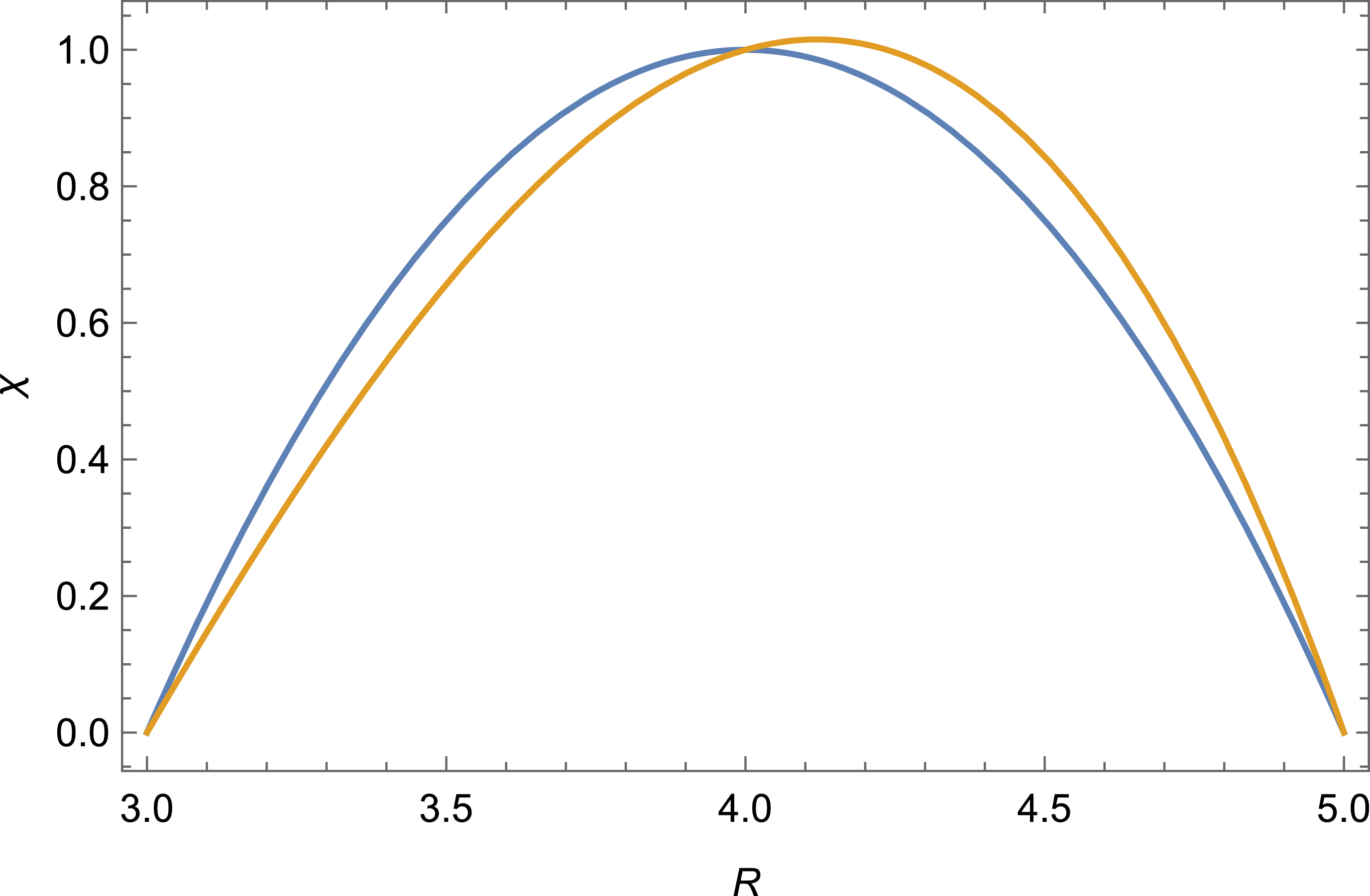
Schematic figure illustrating how the poloidal flux
 $\chi$
may vary along a long a ray (here in terms of the major radius
 $R$
) in a fixed-boundary equilibrium without (blue) and with (orange) plasma pressure. The poloidal flux vanishes at the boundary and peaks on the magnetic axis. With increasing pressure, the magnetic axis moves outward, and the spatial distribution of
 $\chi$
changes accordingly.

In order to quantify the average Shafranov shift, we introduce the functional
 \begin{align} S[\chi ] & = \frac {1}{X} \int _P \chi F {\rm d}V ,\\[-7pt]\nonumber \end{align}
 \begin{align} X & = \int _P \chi {\rm d}V, \end{align}
where
 $F(\boldsymbol {r})$
is a suitably chosen function of the coordinates
 $\boldsymbol {r}$
and the integral is taken over the plasma volume
 $P$
. Here,
 $S[\chi ]$
can be regarded as a
 $\chi$
-weighted average of the function
 $F(\boldsymbol {r})$
over the domain
 $P$
. The Shafranov shift is the amount by which
 $S[\chi ]$
changes due to the redistribution of poloidal flux when pressure is added, see figure 2. To first order in
 $\delta \chi /\chi _0 \ll 1$
, we have
 \begin{align} \delta S = S[\chi _0 + \delta \chi ] - S[\chi _0] = \frac {1}{X} \left ( \int _P \delta \chi F {\rm d}V - S[\chi _0] \int _P \delta \chi {\rm d}V \right ), \end{align}
where the second term in the brackets vanishes if either
 $F(\boldsymbol {r})$
is chosen so that
 $S[\chi _0] = 0$
or the volume integral of
 $\delta \chi$
vanishes.Footnote
6
In the following, we shall assume this to be the case.
Different choices of
 $F$
correspond to different manifestations of the Shafranov shift. For instance, choosing
 $F = \delta (\boldsymbol {r} - \boldsymbol {r}_0)$
is synonymous with declaring an interest in the value of the poloidal flux in the point
 $\boldsymbol {r}_0$
. If this point lies on the magnetic axis of the vacuum field, then
 $\delta S$
measures how far the magnetic axis moves away from that point, due to the addition of pressure, in terms of poloidal flux. (If
 $F$
is chosen in this way, then
 $S[\chi _0] \ne 0$
and we must instead require that the volume integral of
 $\delta \chi$
vanishes.) Another choice of interest is
 \begin{align} F(\boldsymbol {r}) = x(\boldsymbol {r}), \end{align}
where
 $x$
is a coordinate in the plane perpendicular to
 $\boldsymbol {B}_0$
that increases in a direction that is deemed interesting. Then,
 $S[\chi ]$
measures a
 $\chi$
-weighted average of
 $x$
over the domain, and
 $\delta S$
indicates how far the poloidal flux has moved, on average, in the
 $x$
-direction. Whatever the exact definition of
 $F$
, we shall normalise it in such a way that a Shafranov shift of order unity,
 $\delta S = O(1)$
, corresponds to a displacement of the plasma column comparable to the minor radius
 $a$
.
In order to derive a useful expression for
 $\delta S$
, we introduce a function
 $H(\boldsymbol {r})$
such that
 \begin{align} {\nabla} ^2 H = F \end{align}
everywhere in the plasma volume
 $P$
and
 $H=0$
on the boundary. These conditions uniquely determine
 $H$
, which encapsulates the necessary information about the shape of the plasma cross-section and is discussed in Appendix A. Our measure of the Shafranov shift can now be written as
 \begin{align} X \delta S = \int _P \delta \chi {\nabla} ^2 H {\rm d}V = \int _P H {\nabla} ^2 \delta \chi \; {\rm d}V = \mu _0 G \int _P \frac {H J_\|}{B} \; {\rm d}V, \end{align}
where we have used (3.11) and the fact
 $\delta \chi$
vanishes on the boundary. Note that, in RMHD, the Shafranov shift is exclusively caused by the parallel (Pfirsch–Schlüter) current to leading order in
 $\epsilon$
. It is assumed that the net toroidal current vanishes, on each flux surface, both before and after the addition of pressure. The case of a ‘flux-conserving stellarator’ (Freidberg Reference Freidberg2014) is thus not considered.
A general, yet explicit, expression for the Shafranov shift in a stellarator without net toroidal current can be obtained by substituting (2.10) in (3.17),
 \begin{align} \delta S = \frac {\mu _0 G^2}{X} \sum _{m,n\ne 0} \int _P \frac {{\rm d}\kern-1pt p}{{\rm d} \psi } \frac {h_{mn} H}{\iota - n/m} e^{i(m \theta - n \varphi )} \; {\rm d}V, \end{align}
where all necessary information about the magnetic-field geometry is encapsulated in the quantities
 $X$
,
 $h_{mn}$
and
 $H$
.
An equally general upper bound on
 $\delta S$
follows from (3.17) and the Cauchy–Schwarz inequality
 \begin{align} \delta S \leqslant \frac {\mu _0 G}{X} \left [ \int _P H^2 {\rm d}V \int _P \left ( \frac {J_\|}{B} \right )^2 {\rm d}V \right ]^{1/2}, \end{align}
where
 $J_\|$
is related to the pressure by (2.7). It is clear from (3.17) and (3.19) that the Shafranov shift is particularly small in a magnetic field optimised for small Pfirsch–Schlüter current (Wobig Reference Wobig1999).
Before closing this section, we note that there is no way of avoiding the Shafranov shift altogether by optimising the magnetic-field geometry. The average Shafranov shift (3.17) does not vanish for all allowable functions
 $H$
unless the Pfirsch–Schlüter current
 $J_\|$
vanishes everywhere. This happens only if the field lines are geodesics, i.e. if the magnetic field is isodynamic, which is impossible in practice (Helander Reference Helander2014). In the context of axisymmetric fields, Bishop & Taylor (Reference Bishop and Taylor1986) considered the related question (without the RMHD approximation) by asking whether the Grad–Shafranov equation has solutions with identically shaped flux surfaces but different pressure and current profiles.
4. Scalings
From the results above, it is possible to deduce certain general properties of the Shafranov shift in various types of magnetic fields. This is the subject of the present section. The exact choice of the function
 $F$
will be left unspecified except that it is taken to be dimensionless and of order unity, which implies
 $H \sim a^2$
according to the definition (3.16).
4.1. General geometry
In Boozer coordinates, (2.7) becomes
 \begin{align} \frac {\partial u}{\partial \varphi } + \iota \frac {\partial u}{\partial \theta } = - G \frac {\partial\kern-1pt B^{-2}}{\partial \theta } = f(\theta ,\varphi ), \end{align}
where again
 $u = J_\| / (Bp'(\psi ))$
, and since
 $\partial\kern-1pt B/\partial \theta = O(\epsilon )$
in the RMHD ordering, it follows that
 $ u \sim G \epsilon / B^2$
. This general scaling shows how
 $u$
depends on
 $\epsilon$
when
 $\iota$
is order unity, but it is modified if
 $\iota \gg 1$
, in which case an additional factor
 $\iota$
appears in the denominator
 \begin{align} u \sim \frac {G \epsilon }{\iota B^2}. \end{align}
This is perhaps obvious already from (4.1) but can also be verified by inspecting the solution
 \begin{align} u(\theta ,\varphi ) = \int _{\varphi _0}^\varphi f\left [ \theta + \iota ( \varphi ' - \varphi ), \varphi ' \right ] {\rm d} \varphi ', \end{align}
where
 $\varphi _0(\theta ,\varphi )$
is chosen so that
 $u[\theta + \iota ( \varphi _0 - \varphi ),\varphi _0] = 0$
. In the limit
 $\iota \gg 1$
, the integrand
 $g(\varphi ') = f[ \theta + \iota ( \varphi ' - \varphi ), \varphi ' ]$
becomes almost periodic with a period of
 $2 \pi / \iota$
since
 \begin{align} g(\varphi ' + 2\pi / \iota ) - g(\varphi ') = O( \iota ^{-1}). \end{align}
More importantly, its integral over one period is of order
 \begin{align} \int _{\varphi _0 + 2 \pi n/\iota }^{\varphi _0 + 2 \pi (n+1)/\iota } g(\varphi ') {\rm d} \varphi ' = O(\iota ^{-2}), \end{align}
since, by the definition of
 $f(\theta ,\varphi )$
,
 \begin{align} \int _0^{2\pi } f(\theta , \varphi ) {\rm d} \theta = 0. \end{align}
Hence, we conclude that
 $u \sim f/\iota$
, and (4.2) follows if
 $\iota$
is either comparable to, or larger than, unity. If we further estimate, within factors of order unity,
 $G \sim BR$
,
 $\chi \sim \iota \psi \sim \iota B a^2$
, we arrive at a universal scaling of the average Shafranov shift (3.17)
 \begin{align} \delta S \sim \frac {\beta }{\epsilon \iota ^2}. \end{align}
The equilibrium pressure limit is thus expected to scale as (1.1), indicating that Spitzer’s result is of general validity to the present level of accuracy. As long as the magnetic field follows the RMHD ordering, this is how the equilibrium beta limit scales with
 $\epsilon$
and (more approximately) with
 $\iota$
.
Slightly more precise results can be derived for quasisymmetric and QI stellarators, to which we now turn our attention.
4.2. Quasisymmetric stellarators
In a quasisymmetric stellarator without net toroidal current,
 $I=0$
, (2.13) and (3.17) give the following explicit formula for
 $\delta S$
:
 \begin{align} \delta S_{\textrm {QS}} = \frac {\mu _0 G^2}{X} \int _P \frac {p'(\psi )}{N-\iota } \left \langle H \left ( \frac {1}{B^2} - \frac {1}{\langle B^2 \rangle } \right ) \right \rangle {\rm d}V. \end{align}
According to the ordering underlying RMHD, the magnetic-field strength
 $B$
only varies on the long length scale
 $L_\|$
, which is taken to be comparable to the circumference of the torus. In a quasi-axisymmetric (QA) or quasihelically (QH) symmetric stellarator,
 $B$
is constant along the magnetic axis and can therefore only vary by a relative amount of order
 $\epsilon = L_\perp /L_\| \ll 1$
in the entire plasma volume. Again using
 $G \sim BR$
and
 $\chi \sim \iota B a^2$
gives
 \begin{align} \frac {J_{\|}^{\textrm {PS}}}{B} = \frac {G}{N-\iota } \frac {{\rm d}\kern-1pt p}{{\rm d} \psi } \left ( \frac {1}{B^2} - \frac {1}{\langle B^2 \rangle } \right ) \sim \frac {R\kern-1pt B}{N - \iota } \frac {p}{a^2B} \frac {\epsilon }{B^2} = \frac {p}{(N-\iota ) a\kern-1.3pt B^2}, \end{align}
within factors of order unity. It follows that the Shafranov shift (4.8) in a quasisymmetric stellarator is of order
 \begin{align} \delta S_{\textrm {QS}} \sim \frac {\beta }{|N-\iota |\iota \epsilon }, \end{align}
where we have again crudely estimated the poloidal flux by
 $\chi \sim \iota \psi$
. The equilibrium pressure limit is thus expected to scale as
 \begin{align} \beta _{\textrm {QS}} \sim \left | \frac {N}{\iota } - 1 \right | \epsilon \iota ^2. \end{align}
These scalings agree with the classical-stellarator result (1.1) but contain an additional dependence on
 $N / \iota$
.
4.3. QI stellarators
In a QI stellarator, the Shafranov shift must of course follow the approximate general scaling (4.7), but it is also possible to derive a quantitatively precise result. As we have already seen, the Pfirsch–Schlüter current in a QI stellarator without net toroidal current satisfies (2.16), but unlike the quasisymmetric case, there is no closed form for the solution of this equation. It is, however, possible to use (3.19) to derive an upper bound on the Shafranov shift. We start by noting that
 \begin{align} \langle u^2 \rangle = \frac {1}{V'(\psi )} \oint {\rm d} \alpha \int _0^Y u^2 {\rm d}y, \end{align}
where
 ${\rm d}y = {\rm d}l/B$
and the integral
 \begin{align} Y(\psi ) = \int _0^L \frac {{\rm d}l}{B}, \end{align}
is performed along
 $\boldsymbol {B}$
over one period of the device,
 $\varphi \in [0,2\pi /N_p]$
. By using the Poincaré inequality
 \begin{align} \int _0^Y u^2 {\rm d}y \leqslant \left ( \frac {Y}{\pi } \right )^2 \int _0^Y \left ( \frac {\partial u}{\partial y} \right )^2 {\rm d}y, \end{align}
for functions such that
 $u(0) = u(Y) = 0$
, we conclude from (2.16) that
 \begin{align} \langle u^2 \rangle \leqslant \frac {4Y^2}{\pi ^2 V'} \oint {\rm d} \alpha \int _0^L \left ( \frac {\partial \ln B}{\partial \alpha } \right )^2 \frac {{\rm d}l}{B}. \end{align}
Since
 $V'(\psi ) = 2 \pi Y(\psi )$
, this result can be written as
 \begin{align} \left \langle \left ( \frac {J_\|}{B} \right )^2 \right \rangle \leqslant \frac {1}{\pi ^4} \left \langle \left ( p' V' \frac {\partial \ln B}{\partial \alpha } \right )^2 \right \rangle , \end{align}
which can be substituted into (3.19) to give an upper bound on the Shafranov shift in QI stellarators without net toroidal current
 \begin{align} \delta S_{\textrm {QI}} \leqslant \frac {\mu _0 G}{\pi ^2 X} \left [ \int _P H^2 {\rm d}V \int _P \left (p' V' \frac {\partial \ln B}{\partial \alpha } \right )^2 {\rm d}V \right ]^{1/2}. \end{align}
Ignoring factors of order unity in the estimates
 $ V'(\psi ) \sim {2 \pi R}/({N_pB})$
,
 $p'(\psi ) \sim p/(a^2 B)$
and
 \begin{align} \frac {\partial \ln B}{\partial \alpha } \sim \epsilon , \end{align}
gives the scaling
 \begin{align} \delta S_{\textrm {QI}} \:{\stackrel {\textstyle {\lt }}{\sim }}\: \frac {\beta }{N_p\iota \epsilon }, \end{align}
thus suggesting a beta limit
 \begin{align} \beta _{\textrm {QI}} \sim \frac {N_p}{\iota } \epsilon \iota ^2. \end{align}
Apart from the dependence on
 $N_p/\iota$
, this scaling agrees with that for classical stellarators (1.1) and quasisymmetric ones (4.10). It should be noted that, in many cases, (4.18) is likely to be an overestimate of the poloidal magnetic-field-strength variation since the field strength may vary by less than
 $O(\epsilon )$
in the poloidal direction of a QI stellarator. This variation vanishes identically on the contour
 $B = B_{\textrm {max}}(\psi )$
and can be made quite small elsewhere by targetted optimisation of the magnetic-field geometry, which then results in a correspondingly smaller Shafranov shift.
5. Numerical results
In order to explore the Shafranov shift numerically, a series of magnetic equilibria based on the following configurations were computed:
-
(i) the Wendelstein 7-X high-mirror configuration (KJM252);
-
(ii) one of the stable QI designs (SQuIDs) of Goodman et al. (Reference Goodman, Xanthopoulos, Plunk, Smith, Nührenberg, Beidler, Henneberg, Roberg-Clark, Drevlak and Helander2024);
-
(iii) a ‘low-
$\iota$
SQuID’, which was optimised in the same way as (ii) but for a lower average
$\iota$
; -
(iv) a ‘precise QA configuration’ of Landreman & Paul (Reference Landreman and Paul2022);
-
(v) a ‘precise QH configuration’ of Landreman & Paul (Reference Landreman and Paul2022).


Flux-surface plots in Wendelstein 7-X (no changes to boundary coefficients) at three different cross-sections, shown for zero and finite beta.

Flux-surface plots in the SQuID (no changes to boundary coefficients) at three different cross-sections, shown for zero and finite beta.

Figure 4. Long description
Three contour plots depict flux surfaces at different cross-sections for zero and finite beta values. Panel A: The contour plot shows flux surfaces at phi equals 0. The x-axis ranges from 4.8 to 5.5, and the y-axis ranges from -1.0 to 1.0. Two sets of contours are shown, one for beta equals 0 in blue and another for beta equals 1.5 percent in orange. Panel B: The contour plot shows flux surfaces at phi equals pi over 2N. The x-axis ranges from 4.2 to 5.6, and the y-axis ranges from -0.5 to 1.0. Two sets of contours are shown, one for beta equals 0 in blue and another for beta equals 1.5 percent in orange. Panel C: The contour plot shows flux surfaces at phi equals pi over N. The x-axis ranges from 4.2 to 5.4, and the y-axis ranges from -0.4 to 0.4. Two sets of contours are shown, one for beta equals 0 in blue and another for beta equals 1.5 percent in orange.
Flux-surface plots in the precise QA (no changes to boundary coefficients) at three different cross-sections, shown for zero and finite beta.

Flux-surface plots in the precise QH (no changes to boundary coefficients) at three different cross-sections, shown for zero and finite beta.

Figure 6. Long description
Panel A: A contour plot with the x-axis ranging from 1.2 to 1.3 and the y-axis ranging from -0.2 to 0.2. The plot shows contours for two different values of beta, with blue representing beta equals 0 and orange representing beta equals 1.5 percent. The label indicates phi equals 0. Panel B: A contour plot with the x-axis ranging from 0.8 to 1.1 and the y-axis ranging from -0.25 to 0.05. The plot shows contours for two different values of beta, with blue representing beta equals 0 and orange representing beta equals 1.5 percent. The label indicates phi equals pi over 2N. Panel C: A contour plot with the x-axis ranging from 0.65 to 1.0 and the y-axis ranging from -0.05 to 0.05. The plot shows contours for two different values of beta, with blue representing beta equals 0 and orange representing beta equals 1.5 percent. The label indicates phi equals pi over N.
First of all, fixed-boundary equilibria with volume-averaged beta values of
 $\langle \beta \rangle = 0$
and
 $\langle \beta \rangle = 0.015$
were computed using the VMEC code (Hirshman et al. Reference Hirshman, van RIJ and Merkel1986). In the poloidal cross-sections shown in figures 3–6, the outward shift of the flux surfaces can clearly be seen. The shift is smallest in the QH and SQuID configurations, and largest in the QA one. Again, we stress that the net toroidal current is neglected although the bootstrap current may, depending on plasma parameters, be important in QA and QH configurations.
Next, these equilibria were modified in a manner that will now be described. In stellarator design, the shape of the plasma boundary is usually prescribed in terms of Fourier series in cylindrical coordinates
 $(R,\phi ,z)$
 \begin{align} R(\theta ,\varphi ) & = \sum _{m,n} R_{mn} \cos\, (m \theta - nN_p \phi ),\\[-10pt]\nonumber \end{align}
 \begin{align} z(\theta ,\varphi ) & = \sum _{m,n} z_{mn} \sin\, (m \theta - n N_p \phi ), \end{align}
where, for simplicity, we have only included stellarator-symmetric terms. This representation is not unique and can be improved (Henneberg, Helander & Drevlak Reference Henneberg, Helander and Drevlak2021) but provides a simple way to represent the boundary shape, which can be varied by adjusting the coefficients
 $R_{mn}$
and
 $z_{mn}$
.
The values of
 $\delta S$
for all five devices as a function of
 $1/\iota$
with
 $\epsilon$
fixed (left), and as a function of
 $1/\epsilon$
with
 $\iota$
fixed (right). Trend lines showing the expected
 $1/\iota ^2$
and
 $1/\epsilon$
scalings, respectively, are dashed.

In order to investigate the dependence on
 $\iota$
, the rotational transform was varied while the aspect ratio was kept fixed. In the configurations (i)–(iii) listed above, this was accomplished by multiplying all boundary coefficients
 $z_{mn}$
that have
 $n=\pm 1$
by a constant factor
 $k$
, which changes the vertical elongation of the poloidal cross-section of the flux surfaces. Close to the magnetic axis, the cross-section is elliptical and rotates as one goes toroidally around the torus, thus producing rotational transform (Mercier Reference Mercier1964). The elongation of the rotating ellipse in Mercier’s formula for the rotational transform either increases for
 $k\gt 1$
or decreases for
 $k\lt 1$
, and in this way
 $\iota$
is varied on the magnetic axis. The coefficient
 $R_{00}$
is then adjusted in such a way that the aspect ratio remains the same as when
 $k=1$
. In the QH configuration listed under (iv) above, most of the rotational transform comes from torsion of the magnetic axis,Footnote
7
which was therefore varied instead of the ellipticity, by multiplying the coefficients
 $z_{0n}$
by a factor
 $k$
.Footnote
8
The resulting
 $\delta S$
in a series of magnetic fields corresponding to the values
 $k = \{0.8, 0.9, 1, 1.1, 1.2 \}$
are displayed in figure 7. In the definition of
 $\delta S$
, the choices
 \begin{align} F = \frac {R - R_0}{a}, \end{align}
 \begin{align} R_0 = \int \chi _0 R{\rm d}V \bigg / \int \chi _0 {\rm d}V, \end{align}
were made, where
 $R$
is the cylindrical radial coordinate and
 $a$
the minor radius as given by VMEC. This choice ensures
 $S[\chi _0] = 0$
, as required.
The Shafranov shift was also computed in a second set of modified equilibria, shown in the right panel of figure 7, where the rotational transform on axis was held fixed while the aspect ratio was varied. This time, the coefficient
 $R_{00}$
was varied to change the aspect ratio while
 $k$
as adjusted to preserve the on-axis rotational transform
 $\iota$
. The values
 $R_{00} = \{4.55, 5.0, 5.55, 6.0, 6.55\} \mathrm{m}$
were chosen for Wendelstein 7-X,
 $R_{00} = \{4.0, 4.5, 5.0, 5.5, 6.0\}\,\mathrm{m}$
for the SQuID,
 $R_{00} = \{13.82,15.55, 17.27, $
 $19.00, 20.73\}\,\mathrm{m}$
for the low-
 $\iota$
SQuID and
 $R_{00} = \{0.8,0.9,1.0,1.1,1.2\}\,\mathrm{m}$
for precise QA and QH configurations, where
 $R_{00} = 5.55\,\mathrm{}$
,
 $R_{00} = 5.0\,\mathrm{}$
,
 $R_{00} = 17.27\,\mathrm{}$
and
 $R_{00} = 1.0\,\mathrm{m}$
are the values in the original cases.
Modifying optimised equilibria in this simple way generally violates omnigeneity: there is no guarantee that the modified fields remain quasi-symmetric or QI, but they should remain approximately so if
 $k$
is close to unity. This question is discussed in greater detail in Appendix B. An alternative procedure would be re-optimise the equilibria for each value of
 $k\ne 1$
, but such an exercise goes beyond the scope of this paper.
The results in figure 7 all show that the Shafranov shift is a decreasing function of
 $\epsilon$
and
 $\iota$
. The dependence on
 $\iota$
is stronger than that on
 $\epsilon$
, as expected from the general scaling (4.7), which, however, underpredicts the dependence on both parameters. The lack of precise agreement can probably be attributed to the fact that, when the MHD equilibria were modified so as to vary
 $\epsilon$
and
 $\iota$
, many other aspects of the geometry also changed. For instance, when the elongation is varied, the function
 $H$
changes, which is not accounted for in (4.7). This shortcoming of the scaling law is inevitable, since the parameters
 $\epsilon$
and
 $\iota$
only capture a small fraction of all the geometric freedom inherent in stellarator design. This freedom can be used to minimise the Shafranov shift, as is apparent from the fact that the QI and QH examples shown have much smaller shifts than the other configurations, as expected from the theory.
Our QH configurations show particularly poor agreement with the scaling (4.7), which has to do with the fact that the factor
 $1/B^2 - 1 / \left \langle B^2 \right \rangle$
appearing in (4.8) varies much more in the scans than predicted by the simple estimate
 $\epsilon$
used in the scaling. In addition, there is a general complication having to do with the fact that the Shafranov shift displaces the magnetic axis in different directions in different toroidal locations of QH stellarators (Rodríguez Reference Rodríguez2023). The quantity
 $\delta S$
plotted in figure 7 is a weighted average, over the entire plasma volume, of the displacement in the direction of the major radius. In some parts of the plasma, the displacement is negative (i.e. in the direction
 $-\boldsymbol{\nabla }R$
), and the fraction of such parts varies with
 $\epsilon$
and
 $\iota$
. This circumstance, which is not reflected in the scaling, actually causes
 $\delta S$
to become negative if
 $\epsilon$
is increased beyond the displayed points.
6. Conclusions
Most previous treatments of the Shafranov shift have focused on special cases, usually by calculating the shift in specific geometries, either analytically or numerically. By contrast, we have introduced a measure of the average Shafranov shift, which can be calculated in any stellarator with large aspect ratio. The result is given by (3.18) and a generally valid upper bound by (3.19). These results enable a general discussion of the Shafranov shift in entire classes of stellarators rather than individual cases.
The classical scaling (4.7) is found to hold generally for any stellarator with large aspect ratio and rotational transform,
 $\epsilon \ll 1 \ll \iota$
. However,
 $\iota$
is rarely large in practice, and the Shafranov shift depends on additional aspects of the magnetic geometry. For instance, it depends on
 $N$
in quasisymmetric stellarators and
 $N_p$
in QI ones, which can be utilised to make the Shafranov shift small. In QI devices, the Shafranov shift can also be minimised by reducing the poloidal variation of the magnetic-field strength. As a result, recently optimised QI designs have a Shafranov that is only approximately half as large as that in W7-X, and it is yet smaller in QH configurations.
For simplicity, we have limited the discussion to stellarators with small toroidal current. However, the bootstrap current could play an important role in quasisymmetric stellarators, where it can significantly modify the rotational transform, which, in turn, affects the Shafranov shift.
Acknowledgements
Editor Peter Catto thanks the referees for their advice in evaluating this article.
Funding
This work has been carried out within the framework of the EUROfusion Consortium, funded by the European Union via the Euratom Research and Training Programme (Grant Agreement No 101052200 – EUROfusion). Views and opinions expressed are, however, those of the authors only and do not necessarily reflect those of the European Union or the European Commission. Neither the European Union nor the European Commission can be held responsible for them.
Declaration of interests
The authors report no conflict of interest.
Appendix A. The function
$H$

The function
 $H$
defined in (3.16) summarises the information about flux-surface shaping necessary for calculating the average Shafranov shift. Thanks to the orderings of RMHD, only gradients perpendicular to the magnetic field need to be included in the Laplace operator, and (3.16) is thus a Poisson equation in two dimensions that determines
 $H$
separately in each plasma cross-section defined by a cut perpendicular to the magnetic axis. If
 $(x,y)$
denote Cartesian coordinates perpendicular to the magnetic axis in such a cross-section, (3.16) is thus simply
 \begin{align} \frac {\partial ^2 H}{\partial x^2} + \frac {\partial ^2 H}{\partial y^2} = F(x,y). \end{align}
For instance, in the simple case that
 $F = x$
and the cross-section is a circle of radius
 $a$
, the solution becomes
 \begin{align} H = \frac {x}{8} (x^2 + y^2 -a^2). \end{align}
For a generally shaped cross-section,
 $H$
can be calculated by writing
 $H=H_0 + H_1$
, where
 $H_0$
is any solution to the equation
 \begin{align} \boldsymbol{\nabla} ^2 H_0 = F, \end{align}
not necessarily satisfying the boundary condition
 $H_0=0$
, then
 \begin{align} \boldsymbol{\nabla} ^2 H_1 = 0 \end{align}
and
 $H_1=-H_0$
on the boundary. In a circular domain, the solution to this equation is given by Poisson’s integral formula, and the solution in a differently shaped domain can be constructed by conformal mapping.
Appendix B. Non-omnigeneity of modified equilibria
As remarked in the main text, if the original magnetic equilibria are well optimised in the sense that they are exactly omnigenous for
 $k=1$
, they will in general not be omnigenous if
 $k\ne 1$
. However, if
 $k-1 \ll 1$
, the degree of non-omnigeneity should be quadratic at the leading order of the Taylor expansion in this quantity. By contrast, the change in Shafranov shift can be either positive or negative, and therefore its Taylor series has a linear term in
 $k-1$
. It is thus to be expected that
 $\delta S$
varies more rapidly with
 $k$
than the degree of omnigeneity for small values of
 $k-1$
.
To verify these expectations numerically, we plot the quasisymmetry errors in the modified vacuum configurations based on the precise QA and QH in figure 8. In this figure, the quasisymmetry error is defined as
 \begin{align} \text{QS Error} = \frac {1}{V}\int _V \left [(N - \iota )(\boldsymbol {B}\times \boldsymbol{\nabla }B)\boldsymbol{\cdot }\boldsymbol{\nabla }\psi - G\boldsymbol { B}\boldsymbol{\cdot }\boldsymbol{\nabla }B\right ]^2\frac {dV}{B^6}, \end{align}
where
 $V$
is the plasma volume. This is essentially the same metric that is used in the SIMSOPT code (Landreman et al. Reference Landreman, Medasani, Wechsung, Giuliani, Jorge and Zhu2021), except that we take an average over the entire volume instead of weighing different flux surfaces differently.
The quasisymmetry error, as defined in (B1), of the modified vacuum configurations based on the precise QA and QH configurations of Landreman & Paul (Reference Landreman and Paul2022) a function of
 $k$
for the
 $\iota$
scan and of
 $R_{00}$
for the aspect-ratio scan.


 J∥
 Am−2
 s=0.5
 s
 s=0
 s=1
 (θ,φ)
 J∥
 χ
 R
 χ


 δS
 1/ι
 ϵ
 1/ϵ
 ι
 1/ι2
 1/ϵ

 k
 ι
 R00

 Open access

