Introduction
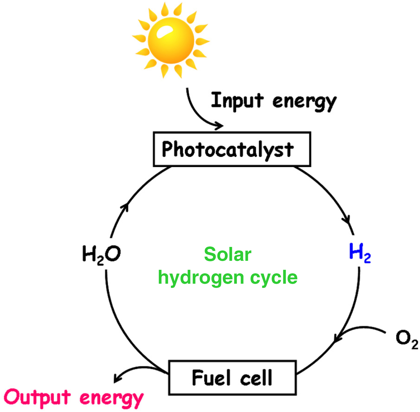
The development of the efficient and green processes for producing hydrogen (H2) is vital for realizing sustainable society. At present, most H2 is produced by the steam reforming of methane at high temperature with the emission of carbon dioxide. If we can produce H2 from water at low temperature using the sunlight as an energy source, an ideal “solar hydrogen cycle” is completed by combining with the fuel cell (Scheme 1). For this purpose, water splitting with a standard Gibbs energy of reaction (ΔrG 0) of +237.13 kJ/mol (Eq. 1) by visible-light semiconductor photocatalysts[Reference Osterloh1–Reference Tachibana, Vayssieres and Durrant3] and photoelectrochemical (PEC) cells[Reference Hisatomi, Kubota and Domen4] has intensively been studied.
 $${\rm H}_{\rm 2}{\rm O} \to {\rm H}_2 + 1/2{\rm O}_2^{} $$
Solar hydrogen cycle by combining with H2/O2 fuel cell.

The semiconductors developed for water splitting need a band gap above ~2 eV, which is much larger than the thermodynamic value of 1.23 eV because of the large overpotential particularly for water oxidation.[Reference Fabian, Hu, Singh, Houle, Hisatomi, Domen, Osterlohf and Ardo5] The increase in the band gap lowers the light harvesting efficiency (LHE), while it increases the stability. So far, no efficient and stable water splitting by a single photocatalytic material has been achieved. An alternative way is using metal chalcogenide quantum dot (MX QD, X = S, Se, Te)-sensitized PEC (SPEC) cells.[Reference Lianos6, Reference Sahai, Ikram, Rai, Shrivastav, Dass and Satsangi7] The metal chalcogenide QDs possess unique features as the photosensitizer: (i) tunability of the band gap or the band edge levels by the size quantization[Reference Weller8, Reference Tada, Fujishima and Kobayashi9] and the concentrations of S2− and OH− ions in the electrolyte solution[Reference Frese and Canfiled10] to enhance the redox abilities of photogenerated charge carriers, (ii) great extinction coefficient >104/M/cm or large LHE,[Reference Yu, Qu, Guo and Peng11, Reference Jasieniak, Smith, van Embden and Malvaney12] and (iii) large dipole moment enhancing charge separation.[Reference Diguna, Shen, Kobayashi and Toyoda13] On the other hand, Au nanoparticle (NP)-loaded metal oxides (Au/MOs) represented by Au/TiO2 have emerged as a new type of visible-light photocatalysts.[Reference Kubacka, Fernandez-Garcia and Colon14–Reference Panayotov and Morris17] The so-called plasmonic photocatalyst has great potential for efficient solar-to-chemical transformations because Au NP possesses strong and broad absorption due to the localized surface plasmon resonance (LSPR) well matching the solar spectrum. While the Au/TiO2 plasmonic photocatalyst has mainly been applied to various organic syntheses so far,[Reference Kowalska, Abe and Ohtani18–Reference Naya, Niwa, Kume and Tada24] it has recently been shown to exhibit visible-light activity for water splitting.[Reference Liu, Hou, Pavaskar, Aykol and Cronin25–Reference Zhong, Ueno, Mori, Shi, Oshikiri, Murakoshi, Inoue and Misawa27] In this manner, MX QDs and Au NP are highly promising photosensitizers in the photoanode of the PEC cells for H2 generation from water. A coming big challenge is increasing the solar-to-hydrogen efficiency (STHE) by the hybridization of the sensitizers.
This article describes the design and synthesis of MX QD- and Au NP-based nanohybrid sensitizers with atomically commensurate junction or heteroepitaxial (HEPI) junction between the components, and further, the application as the photoanode of the PEC cell for H2 generation from water.
Basic structure of QD-SPEC cells
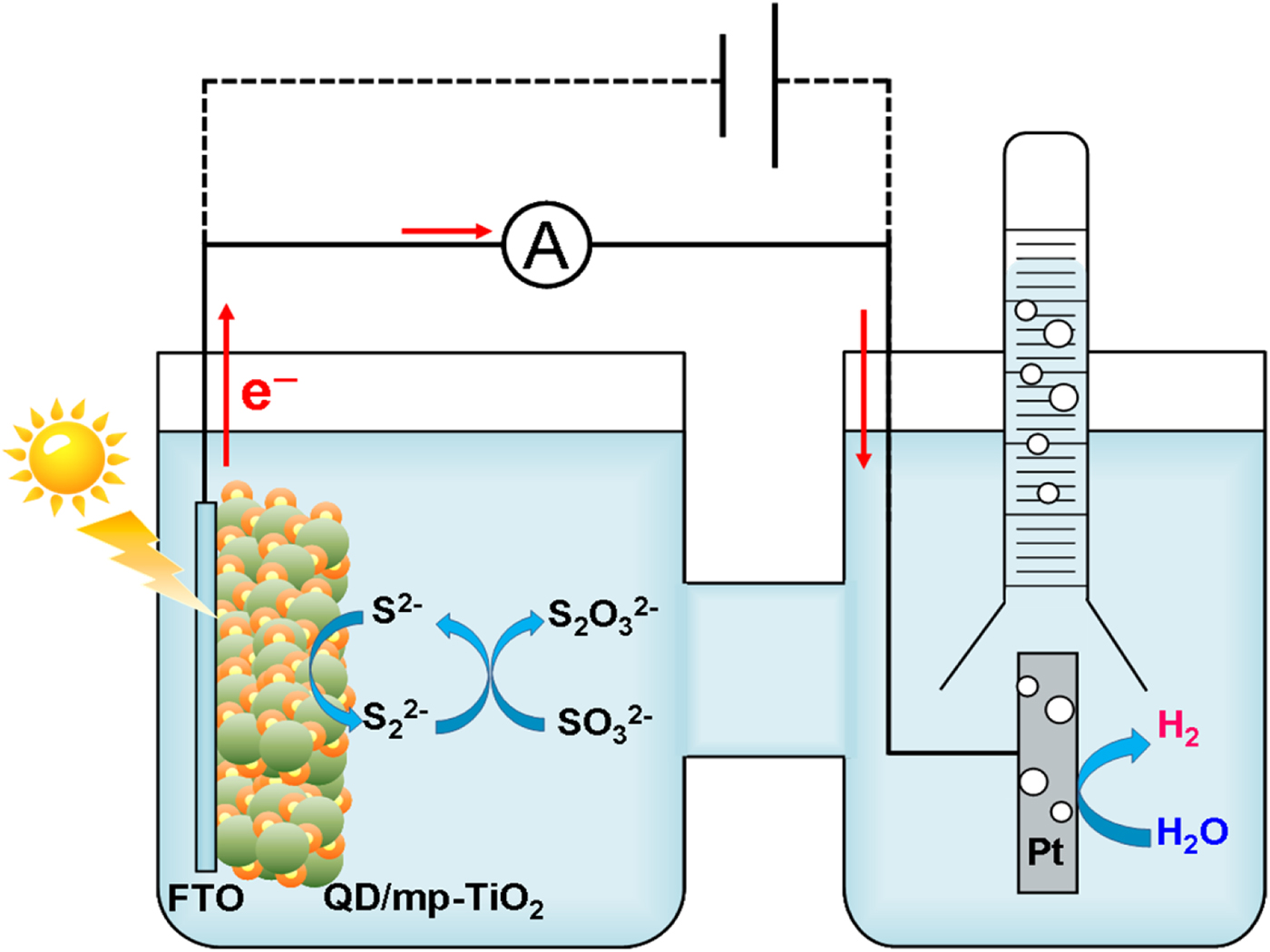
The prototype of two-electrode QD-SPEC cell for H2 generation from water consists of QD-loaded mesoporous TiO2 nanocrystalline film coated on fluorine-doped tin oxide (QD/mp-TiO2/FTO) photoanode, Pt cathode, and aqueous electrolyte solution (photoanode|electrolyte solution|cathode) (Scheme 2). QDs of MXs such as CdS and CdSe possess the excellent properties as the photosensitizer, but they undergo dissolution under the band gap excitation.[Reference Meissner, Memming, Kastening and Bahnemann28] To solve this serious problem, aqueous solution of S2− ions can be effectively used as the electrolyte.[Reference Tachibana, Akiyama, Ohtsuka, Torimoto and Kuwabata29] The solubility product (K sp) of MXs is extremely low.[Reference Licht30] Also, S2− ion with a standard redox potential [E 0(S2−/S) = −0.447 V) (versus standard hydrogen electrode, SHE) is a much better electron donor than H2O [E 0(H2O/O2) = + 1.23 V]. The progress of S2− oxidation accumulates sulfur species on the QD surface, which can be reduced back to S2− ions by SO32− ions.[Reference Bühler, Meier and Beber31] Consequently, the addition of S2− ions into the electrolyte solution thermodynamically and kinetically suppresses the QD photodissolution, while the co-presence of SO32− ions improves the sustainability of the cell performance. Such QD-SPEC cells can be operated safely because H2 is generated in the gas phase without O2.
Basic structure of the QD-sensitized PEC cell for hydrogen generation from water. Fluorine-doped tin oxide (FTO) works as the electron-collecting electrode.

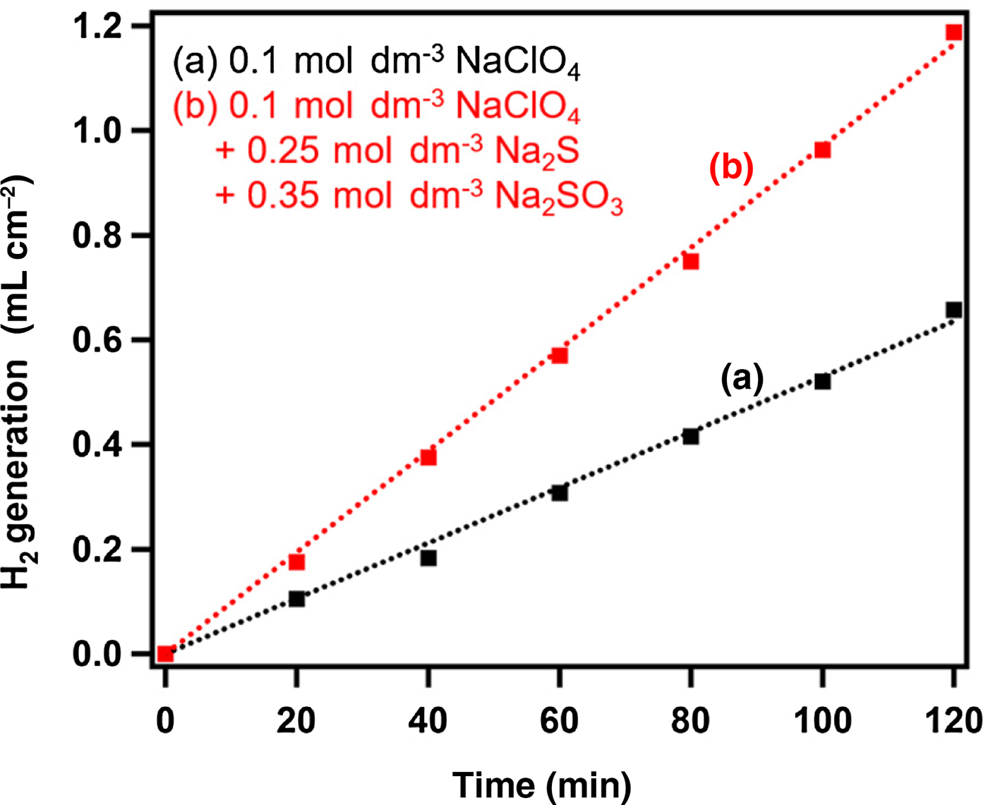
Poisoning of noble metals such as Pt by sulfur is well known in the field of catalysts. Unexpectedly, the comparison between the rates for hydrogen evolution reaction (HER) from water (a) and aqueous solution containing S2− and SO32− ions (b) at −1.3 V versus SHE indicates that the presence of S2− ions in water accelerates the HER on Pt (Fig. 1). In the QD-SPEC cells, S2− and SO32− ions in the electrolyte solution not only stabilize the QD/TiO2 photoanode but also accelerate the HER at the Pt cathode.
Time courses for HER on Pt electrode from (a) 0.1 M aqueous solution of NaClO4 (pH 13.5) and (b) aqueous solution containing 0.1 M NaClO4, 0.25 M S2− ions and 0.35 M Na2SO3 (pH 13.5) at −1.3 V versus SHE in the dark.

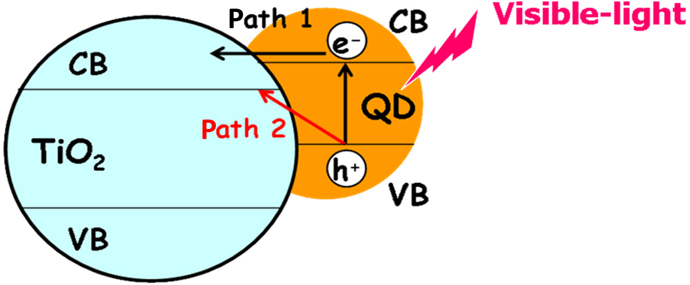
Visible-light irradiation of the photoanode promotes the electrons in the valence band (VB) of QD to the conduction band (CB) to induce electron injection into the CB of TiO2 (path 1). On the other hand, the VB holes in the QD preferentially oxidize S2− ions. The CB electrons are transported to the electron-collecting FTO electrode further to the Pt cathode through the external circuit, reducing water there. The overall reaction expressed by Eq. 2 is energetically uphill with the ΔrG 0 = +44.3 kJ/mol.[Reference Gonzalez-Pedro, Zarazua, Barea, Fabregat-Santiago, de la Rosa, Mora-Sero and Gimenez32]
 $$2{\rm H}_{\rm 2}{\rm O} + 2{\rm S}^{2 -} + {\rm SO}_3^{2 -} \to {\rm H}_2 + 2{\rm O}{\rm H}^ - + {\rm S}_2{\rm O}_3^{2 -} $$
Design for the photoanode
The incident photon-to-current efficiency (IPCE, Eq. 3) is an important indicator for the performance of the QD-SPEC cell at incident-light wavelength (λ).
 $${\rm IPCE} = {\rm LHE} \times \phi _{{\rm inj}} \times \phi _{{\rm trans}} $$
where the LHE is defined by [1–10−A(λ)] as a function of absorbance of the photoanode (A), ϕ inj is the charge injection efficiency. The efficiency of the electron transport to FTO (ϕ trans) is reduced by loss processes (ϕ loss) to 1–∑ϕ loss.
Integration of the product of the IPCE and Faraday efficiency (η F) with respect to λ yields the STHE (Eq. 4).
 $${\rm STHE} = \int {\rm IPCE}(\lambda ) \times \eta _{\rm F}d\lambda $$
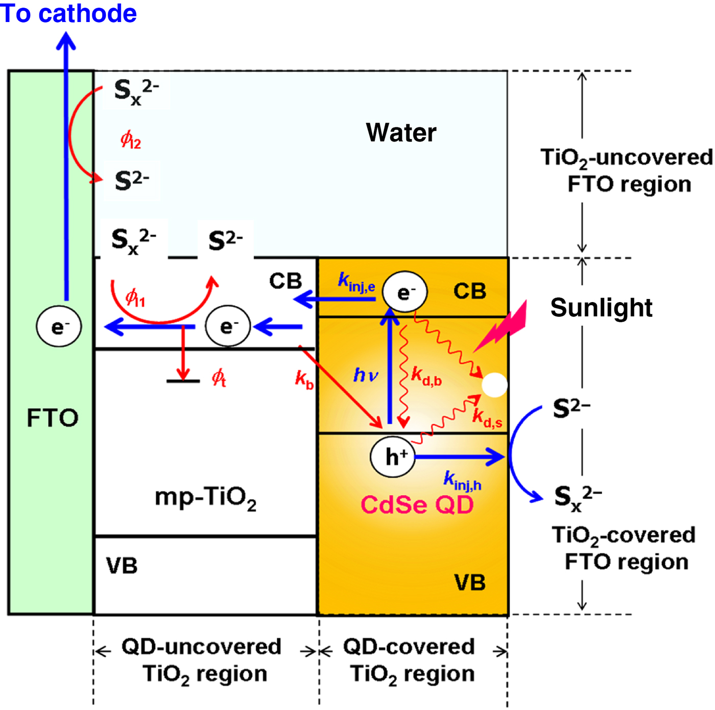
The basic strategy for increasing IPCE is explained as follows (Scheme 3). The particle size of QDs strongly affects the light absorption and scattering property. Downsizing of QDs decreases the total A due to the size quantization, while increasing the driving force for the charge injection.[Reference Jin-nouchi, Naya and Tada33] The addition of S2− ions into the electrolyte solution effectively suppresses the electron–hole recombination. On the way to FTO, the electrons can be trapped at the defects and grain boundaries particularly in the mesoscopic TiO2 film, and thus, the ϕ trans decreases to (1–ϕ t). The TiO2-surface coverage by QDs is usually low, and in the uncovered region, part of the electrons once injected into TiO2 are lost by the reduction of oxidants in the electrolyte solution.[Reference Mora-Seró, Giménez, Fabregat-Santiago, Gómez, Shen, Toyoda and Bisquert34] As a result, the ϕ trans is reduced to (1–ϕ t–ϕ l1). Additionally, the electrolyte solution can penetrate into the pores of mp-TiO2 to be contact with FTO uncovered with TiO2, and the back reaction at the interface further reduces ϕ trans to (1–ϕ t–ϕ l1–ϕ l2). The increase in the TiO2-surface coverage by QDs can also suppress the back electron transfer from TiO2 to the oxidants because the QD with a higher CB minimum than TiO2 acts as the energy barrier. Consequently, the requirements of the photoanode to achieve high STHE can be summarized: (i) LHE enhancement, (ii) promotion of the electron and hole injection from the QD into TiO2 or electron donors, respectively, and (iii) the efficient electron transport by the suppression of the back electron transfer from TiO2 and FTO to the oxidants in the electrolyte solution.
Charge transfer processes in the photoanode of the QD-sensitized PEC cell.

Interface between QD and TiO2
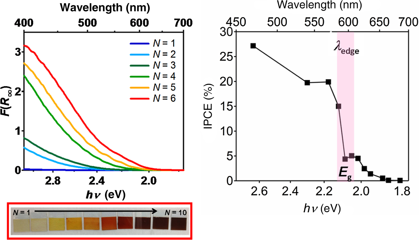
This section deals with the mechanisms on the photoinduced interfacial electron transfer (IFET) from QDs to TiO2. In 1984, the interparticle electron transfer was discovered in a mixed colloid containing CdS and TiO2 particles without chemical bonding between them.[Reference Serpone, Bergarello and Grätzel35] While it is so far believed that the electrons are exclusively injected via path 1, the interfacial chemical bonding between QD and TiO2 can affect the electron injection process. UV-Vis absorption spectra for CdSe/mp-TiO2 prepared by the successive ionic layer adsorption and reaction (SILAR) with varying cycle number (N) indicate that the increase in N causes a redshift in the absorption edge (λ edge) and a decrease in the band gap [Fig. 2(a)]. The band gap for bulk-state CdSe is 1.74 eV,[Reference Lide36] and thus, the larger band gap can be attributed to the quantum size effect. ITCE can be experimentally determined from the photocurrent (J ph) as a function of incident-light wavelength (λ), and the IPCE was calculated by Eq. 5.
 $${\rm IPCE(}\% {\rm )} = (J_{{\rm ph}}N_{\rm A}hc/IF\lambda ) \times 100$$
where N A is the Avogadro constant, I (W/cm2) is the light intensity, F is the Faraday constant, h is the Planck constant, and c is the speed of light. In the IPCE action spectrum for the CdSe/mp-TiO2/FTO photoanode [Fig. 2(b)], there exists a significant discrepancy between the rising potential of photocurrent (1.9 eV) and the band gap (E g≈2.1 eV).
(a) UV-Vis absorption spectra for CdSe/mp-TiO2 with varying N. (b) IPCE action spectrum for the CdSe (N = 6)/mp-TiO2 photoanode in a three-electrode QD-sensitized PEC cell with Ag/AgCl as the reference electrode. (Adapted/reproduced with permission from Ref. Reference Yoshii, Kobayashi and Tada37, Wiley-VCH, 2015.)

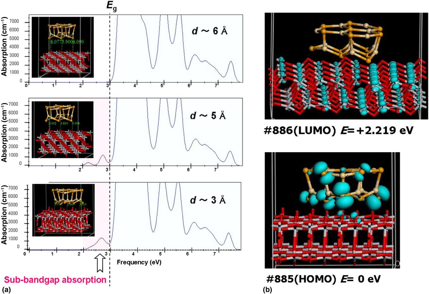
Density functional theory (DFT) calculations were performed for a model system with a CdSe cluster placed on a TiO2 slub. The optimized structure has the nearest distance between the cluster and the TiO2 surface (d) of ~3 Å. The excitation spectra were calculated for the systems as a function of d [Fig. 3(a)]. At d = 6 Å, the interband transition is only observed at photon energy larger than the band gap. At d≤5 Å, weak absorption appears at photon energy below the band gap. In the electron density contour maps, the HOMO is localized on the Se atoms mainly constituting the VB maximum of CdSe, while the LUMO is localized on Ti atoms mainly constituting the CB minimum of TiO2. Therefore, the absorption near the tail edge of CdSe/mp-TiO2 is ascribable to the interfacial electron transition from CdSe QD levels to TiO2 (path 2) (Scheme 4).[Reference Yoshii, Kobayashi and Tada37] A similar result was obtained in the directly coupled CdS/TiO2 system.[Reference Fujishima, Nakabayashi, Takayama, Kobayashi and Tada38]
(a) DFT-calculated excitation spectra for (CdSe)13/(TiO2)64 with varying the distance between CdSe cluster and TiO2 surface (d). The d is ~3 Å for the optimized structure. (b) Electron density contour maps for the HOMO and LUMO. (Adapted/reproduced with permission from Ref. Reference Yoshii, Kobayashi and Tada37, Wiley-VCH, 2015.)

Schematic representation of the mechanism on the electron injection from CdSe QD to TiO2.

The interfacial bond between CdSe (or CdS) and TiO2 leads to the extension of the spectral response of the photoanode. Also, the ϕ inj in path 2 [=k inj,e/(k inj,e + k b)] is larger than the value in path 1 [=k inj,e/(k inj,e + k d,b + k d,s + k b)] (Scheme 3). Thus, the interfacial chemical bond formation can contribute to the increase in the STHE.
Interface between the components of nanohybrids
Synthesis of hybrid QDs
SILAR and chemical bath deposition
The SILAR and CBD are usually used for the preparation of the photoanodes for the QD-SPEC cells. CdS and CdSe QDs are the most popular inorganic photosensitizer for wide gap semiconductors such as TiO2 and ZnO. A directly coupled-bilayer consisting of CdS QD underlayer and CdSe overlayer was formed on mp-TiO2 (CdSe/CdS/mp-TiO2) by the SILAR method and subsequent CBD method at 95°C,[Reference Lee, Chi and Liau39–Reference Kim and Yong41] and on ZnO-nanowires (NWs) by the CBD method at 80°C.[Reference Wang, Yang, Qian, Zhang and Li42] CdS/PbS/mp-TiO2 was prepared by the successive deposition of PbS and CdS QDs on mp-TiO2 using the SILAR method.[Reference Trevisan, Rodenas, Gonzalez-Pedro, Sima, Sanchez, Barea, Mora-Sero, Fabregat-Santiago and Gimenez43] Comprehensive review papers on the SILAR and CBD methods have been reported.[Reference Hodes44, Reference Albero, Clifford and Palomares45]
Hot-injection colloidal synthesis
In the field of colloid chemistry, beautiful hybrid nanocrystals such as MX–MX systems with high-quality junctions have been synthesized by the hot-injection method at temperatures above 150°C. PbS(core)–CdS(shell) (PbS–CdS)/mp-TiO2 was prepared via the hot-injection synthesis of PbS QDs at 150°C followed by the ion exchange between Pb2+ and Cd2+.[Reference Jin, AlOtaibi, Benetti, Li, Zhao, Mi, Vomiero and Rosei46] Also, CdS–CdSe nanocrystals were synthesized at 230°C by the hot injection, and then, fixed on TiO2-NWs by the post ligand-assisted method.[Reference Qiu, Wang, Xu, Wang, Lin and Xie47] While this system has a high-quality interface between CdS and CdSe, the hybrid QDs are indirectly bonded to TiO2 through a linker molecule.
Photodeposition
The photodeposition emerged as an in situ technique for building single-component QD/TiO2.[Reference Tada, Fujishima and Kobayashi9, Reference Kozytskiy, Stroyuk, Kuchmy, Streltsov, Skorik and Mskalyuk48] This technology is applicable to not only MO supports but also non-MO ones such as graphitic carbon nitride (g-C3N4).[Reference Ding, Li, Zhao, Zhu, Li, Deng and Wang49] Recent studies on the low-temperature synthesis of NH/TiO2 systems with HEPI junctions by the photodeposition technique are reviewed below, where the symbol # denotes the HEPI junction.
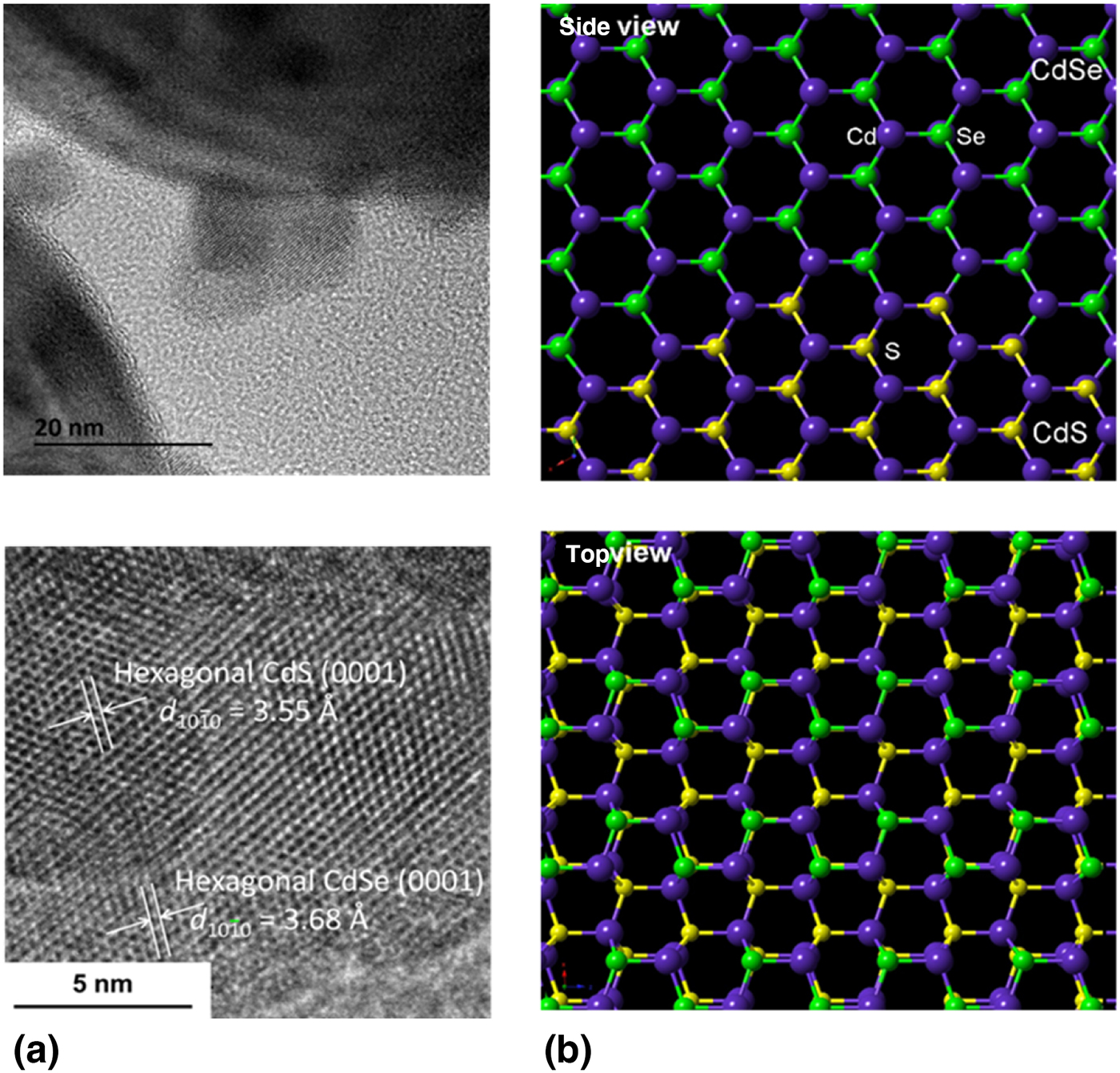
As a typical example for the semiconductor–semiconductor hybrid QDs, the synthesis of CdS–#CdSe/TiO2 by the photodeposition technique is described.[Reference Kitazono, Akashi, Fujiwara, Akita, Naya, Fujishima and Tada50] First, CdS QDs were photodeposited on TiO2 in ethanol solutions of S8 and Cd(ClO4)2 at 25°C (CdS/TiO2), which proceeds via the atomic route.[Reference Fujii, Nagasuna, Fujishima, Akita and Tada51] Next, the two-step photodeposition technique was applied to prepare CdS–CdSe/TiO2.[Reference Fujishima, Tanaka, Sakami, Wada, Morii, Hattori, Sumida and Tada52] The transmission electron microscopy (TEM) image (upper) and the high-resolution (HR)-TEM image (bottom) show that the d-spacings of the core and shell are in agreement with the values for the hexagonal CdS(0001) and hexagonal CdSe(0001) crystal planes, respectively [Fig. 4(a)]. The CdSe shell is heteroepitaxially grown on the surface of the CdS core. In a model for the CdS–CdSe heterojunction, an atomically commensurate interface is formed due to the close lattice constants for CdSe [Fig. 4(b)].
(a) TEM and HR-TEM images for a CdS–#CdSe nanocrystal on TiO2. (b) A model for heteroepitaxial junction between CdS and CdSe: Cd (purple), S (yellow), Se (green). (Adapted/reproduced with permission from Ref. Reference Kitazono, Akashi, Fujiwara, Akita, Naya, Fujishima and Tada50, Wiley-VCH, 2017.)

Synthesis of Au-based bimetallic NPs
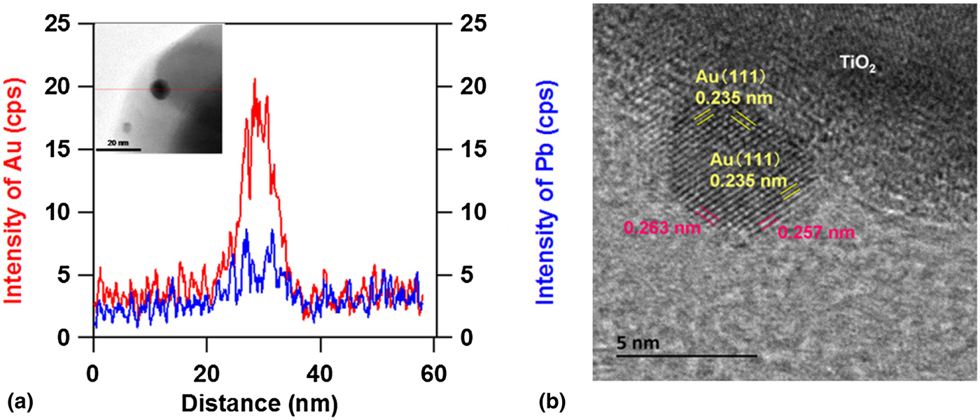
Au NPs were conveniently deposited on TiO2 by the deposition precipitation method,[Reference Tsubota, Haruta, Kobayashi, Ueda, Nakahara, Poncelet, Jacobs, Grange and Delmon53] and the Au mean particle size can be controlled by the post-heating temperature.[Reference Tada, Kiyonaga and Naya54] Au-based bimetallic NPs with a core–shell structure (Au–M) can be formed on TiO2 by the photodeposition technique.[Reference Tada, Suzuki, Ito, Kawahara, Akita, Tanaka and Kobayashi55] By using this technique, an ultrathin Pb shell was formed on the surface of Au NP of Au/TiO2.[Reference Negishi, Naya, Kobayashi and Tada56] Elemental line analysis by energy-dispersive x-ray spectrometry shows the presence of two sharp Pb-signal peaks near both the ends of the Au signal [Fig. 5(a)]. In the HR-TEM image, the d-spacing for the interior of the metal NP is in agreement with that for Au(111) (0.235 nm) [Fig. 5(b)]. The d-spacing near the outermost surface (0.257–0.263 nm) takes an intermediate value between the Au(111) value and the Pb(111) value (0.286 nm). In this manner, Pb is heteroepitaxially grown on the Au(111) surface of Au/TiO2 to yield Au–#Pb/TiO2 with shrinkage of the Pb(111) lattice. Importantly, the Pb shell on Au NP possesses resistance to oxidation,[Reference Mulvaney, Giersig and Henglein:57] whereas Pb NP deposited on TiO2 easily undergoes aerobic oxidation.
(a) EDS-line analysis for a metal particle obtained from UV-irradiated Au/TiO2 in 0.5 mM Pb(NO3)2 aqueous solution. (b) HR-TEM image for Au–#Pb/TiO2. (Adapted/reproduced with permission from Ref. Reference Negishi, Naya, Kobayashi and Tada56, Wiley-VCH, 2017.)

Nanohybrid-SPEC cells for hydrogen generation
The STCE and STHE can be determined by measuring the photocurrent (J ph) and the rate of H2 generation for two-electrode PEC cells by Eqs. 6 and 7, respectively, as a function of applied voltage (E app).
 $${\rm STCE (}\% {\rm )} = \left\{ {\left( {E_{{\rm rev}}- E_{{\rm app}}} \right)J_{{\rm ph}}/I} \right\} \times 100$$
 $${\rm STHE(}\% {\rm )} = {\rm STCE} \times \eta _{\rm F} $$
where E rev (V) is the standard state reversible potential for the overall cell reaction, and I is the light intensity (100 mW/cm2, AM 1.5).
The E rev values for water splitting (Eq. 1) and the reaction with S2− and SO32− ions (Eq. 2) are +1.23 and +0.23 V,[Reference Gonzalez-Pedro, Zarazua, Barea, Fabregat-Santiago, de la Rosa, Mora-Sero and Gimenez32] respectively.
QD-SPEC cells using a single-component MX QD photoanode has recently been reviewed.[Reference Lianos6, Reference Sahai, Ikram, Rai, Shrivastav, Dass and Satsangi7] Here advanced NH-SPEC cells for H2 generation from water are described.
Hybrid QD-SPEC cells
In the bulk state, the electron injection into TiO2 via path 1 from CdS is energetically more advantageous than that from CdSe because the former has a higher CB edge level than the latter with respect to the CB of TiO2.[Reference Grätzel58] Meanwhile, the LHE for CdS (λ edge = 520 nm) is lower than that of CdSe (λ edge = 720 nm). Recent studies have greatly progressed the CdS–CdSe hybrid QD-SPEC cells.
Li and co-workers reported a unique double-sided CdS and CdSe QD co-sensitized ZnO NWs photoanode for the QD-SPEC cells.[Reference Wang, Yang, Qian, Zhang and Li42] A significant hybridization effect was shown in a three-electrode QD-SPEC cell with the structure of CdSe/CdS/ZnO-NWs|Ag/AgCl (reference electrode)|0.25 M Na2S + 0.35 M Na2SO3|Pt. At the photoanode potential (E) = 0 V (versus Ag/AgCl), the IPCEs were higher than 30% at 325<λ<600 nm with a peak of ~45% at λ≈400 nm. The high IPCE was attributed to the spectral extention (LHE↑) and the efficient IFET in the direction of CdSe→CdS (ϕ inj↑).
Lee et al. reported a three-electrode QD-SPEC cell with a similar structure of CdSe/CdS/mp-TiO2|Ag/AgCl|0.24 M Na2S + 0.35 M Na2SO3|Pt.[Reference Lee, Chi and Liau39] A high saturated photocurrent of 14.9 mA/cm2 was obtained under one-sun illumination at E > −0.6. In the CdSe/CdS/mp-TiO2 photoanode cell, the IPCE at λ = 500 nm reached ~60%, while CdSe/mp-TiO2 and CdS/mp-TiO2 cells were ~25% and ~5%, respectively. Further, a rate of hydrogen evolution of 5.4 mL/h/cm2 was achieved by passivating the photoanode with a ZnS overlayer (ZnS/CdSe/CdS/mp-TiO2).[Reference Diguna, Shen, Kobayashi and Toyoda13] The authors deduced that the high performance of the QD-SPEC cell results from the smooth IFET in the direction of CdSe→CdS→TiO2 due to the stepwise band alignment (ϕ inj↑).
Yong and co-workers reported a maximum photocurrent of 9.15 mA/cm2 at E = 0 V (versus saturated calomel electrode, SCE) for a three-electrode QD-SPEC cell with the structure of CdSe/CdS/ZnO-NWs|SCE|1 M Na2S|Pt under one-sun illumination.[Reference Seol, Kim, Kim and Yong40] The photocurrent is significantly larger than 7.23 mA/cm2 for the QD-SPEC cell with the single-component QD/ZnO-NWs photoanode. The authors attributed the co-sensitized effect on the cell performance to the spectral extension (LHE↑).
Kim and Yong obtained a saturated photocurrent density of 17.5 mA/cm2 at E = 0.2 V versus SHE for a three-electrode QD-SPEC cell with the structure of CdSe/CdS/hierarchical ZnO-NWs|Ag/AgCl|0.25 M Na2S + 0.35 M Na2SO3|Pt under one-sun illumination.[Reference Kim and Yong41] The surface modification of the photoanode with IrOx·nH2O further enhanced the photostability as well as the cell performances (ϕ inj↑). H2 evolution with a rate of 5.8/mL/h/cm2 was confirmed. The high activity of the photoanode was attributed to the strong light absorption due to the heavy loading of QD on the large surface area of hierarchical ZnO-NWs and its light-scattering effect (LHE↑) in addition to the smooth directional electron transport through 1D-NW (ϕ trans↑).
Xie and co-workers reported a power conversion efficiency of 2.18% for a two-electrode QD-SPEC cell with the structure of CdS–CdSe/TiO2-NWs|2 M Na2S + 2 M S + 0.2 M KOH (solvent, methanol:water = 7:3 v/v)|Cu2S under one-sun illumination.[Reference Qiu, Wang, Xu, Wang, Lin and Xie47] The authors showed by means of open-circuit photovoltage decay measurements (vide post, Eq. 7) and electrochemical impedance spectroscopy that the hybrid QD enhances the electron injection (ϕ inj↑) and charge transfer properties (ϕ trans↑).
As a great progress, the research groups of Mora-Sero and Gimenez extended the photoresponsivity from visible to near-infrared region by using the CdS/PbS-cosensitized photoanode.[Reference Trevisan, Rodenas, Gonzalez-Pedro, Sima, Sanchez, Barea, Mora-Sero, Fabregat-Santiago and Gimenez43] One-sun illumination of a three-electrode QD-SPEC cell with the structure of CdS/PbS/mp-TiO2/compact-TiO2|Ag/AgCl|0.25 M Na2S + 0.35 M Na2SO3|Pt generated a photocurrent of 6 mA/cm2 and H2 with a rate of 2.5 mL/h/cm2. The IPCE action spectrum demonstrated that the QD-SPEC cell works at 300–900 nm. The compact TiO2 layer underlying the mp-TiO2 film suppresses the back electron transfer from FTO to the oxidant in the electrolyte solution (ϕ trans↑).[Reference Tachibana, Umekita, Otsuka and Kuwabata59]
Rosei and co-workers reported a three-electrode QD-SPEC cell with the structure of ZnS/CdS/PbS–CdS/mp-TiO2/compact-TiO2|Ag/AgCl|0.25 M Na2S + 0.35 M Na2SO3|Pt.[Reference Jin, AlOtaibi, Benetti, Li, Zhao, Mi, Vomiero and Rosei46] An impressive co-sensitized effect was observed in the IPCEs above 20% at λ<830 nm with a peak of ~50% at 400 nm. The saturated photocurrent of 11.2 mA/cm2 under one-sun illumination is equivalent to the rate of H2 generation of 112 mL/cm2/day by assuming η F = 1. The high activity in the visible-to-near-infrared region was ascribable to the co-sensitization by Pb–CdS QDs (LHE↑).
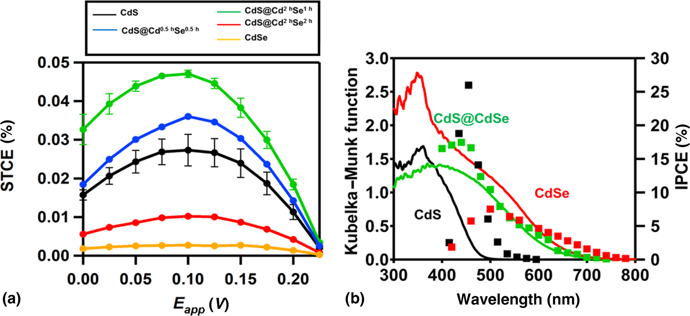
We have recently reported a two-electrode QD-SPEC cell for H2 generation from water with the structure of CdS–#CdSe/mp-TiO2|0.25 M Na2S + 0.35 M Na2SO3|Pt.[Reference Kitazono, Akashi, Fujiwara, Akita, Naya, Fujishima and Tada50] CdS–#CdSe(t p1 = 1 h, t p2 = 2 h)/mp-TiO2 provides a maximum STCE of 0.048% around E app = 0.1 V, which is about twice the value for CdS/mp-TiO2 and ~18 times the value for CdSe/mp-TiO2 [Fig. 6(a)]. The CdS–#CdSe/mp-TiO2 system stably produces H2 with a rate of 0.26 mL/h/cm2 surpassing the rate of 0.12 mL/h/cm for the CdS/mp-TiO2 system. The STHE for the CdS–#CdSe/mp-TiO2 photoanode cell was calculated to be 0.042% by multiplying the η F value of 0.87. While CdSe/mp-TiO2 responds to light at λ < 750 nm with IPCE <~8%, the IPCE for CdS/mp-TiO2 reaches ~20% only at λ<500 nm [Fig. 6(b)]. In the CdS–#CdSe/mp-TiO2 system, the photocurrent onset wavelength (λ on) is located at 680 nm, and the IPCE is approximately the sum of those for CdSe/mp-TiO2 and CdS/mp-TiO2.
(a) STCEs as a function of E app for various PEC cells under simulated sunlight (AM 1.5, one sun, λ>430 nm). (b) IPCE action spectra. (Adapted/reproduced with permission from Ref. Reference Kitazono, Akashi, Fujiwara, Akita, Naya, Fujishima and Tada50, Wiley-VCH, 2017.)

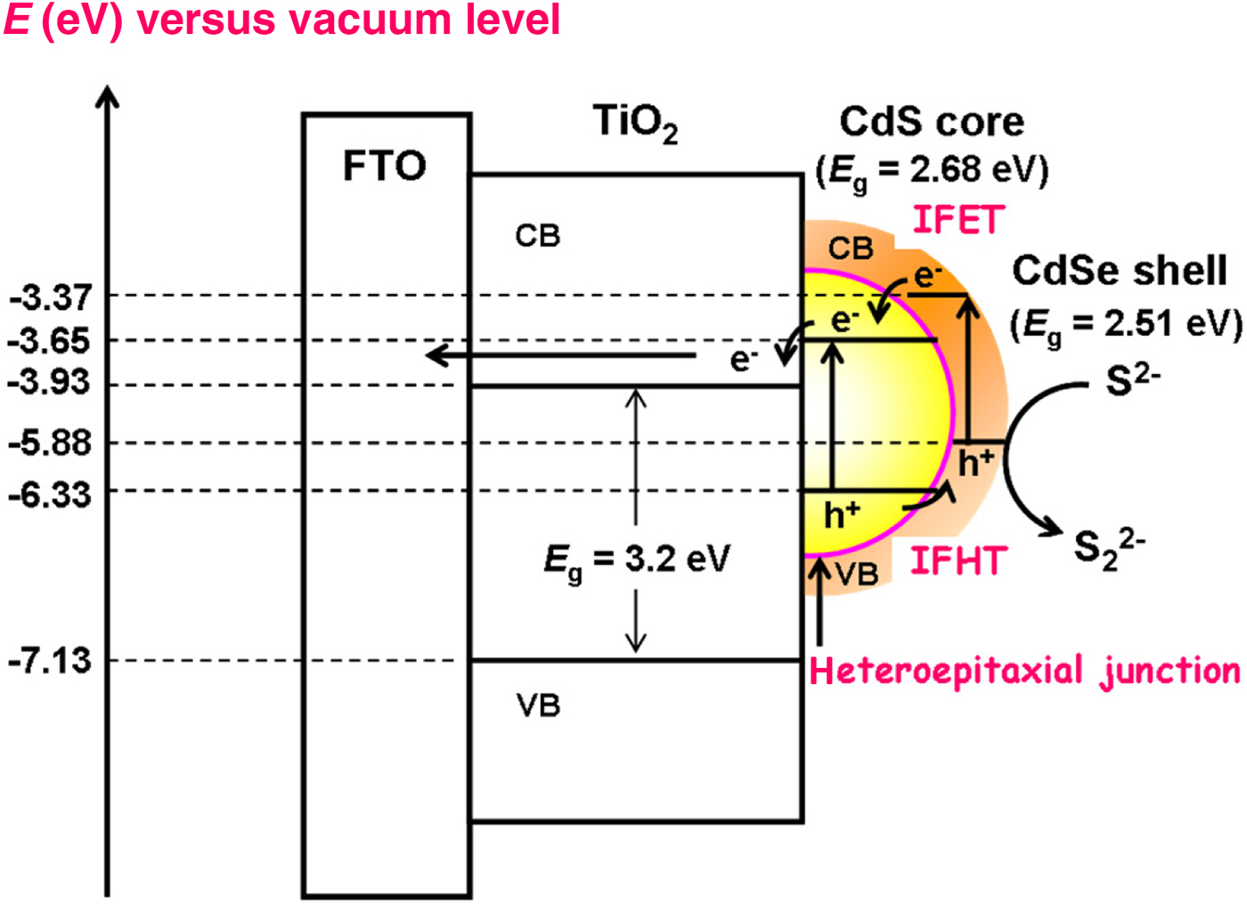
A uniqueness in this MX–MX system is that the potential-determining ions or S2− and OH− selectively act on the CdSe shell since the CdS core is not in contact with the electrolyte solution. The band energy diagram for CdS–#CdSe/mp-TiO2 can be constructed by considering the quantum size effects of the CdS core and CdSe shell[Reference Brus60] and the effect of the concentrations of S2− ions and OH− ions on the band edge of the CdSe shell (Scheme 5).[Reference Tada, Fujishima and Kobayashi9] Visible-light irradiation simultaneously excites the CdS core and CdSe shell. The IFET from CdS and CdSe QDs into TiO2 can occur via path 1 and path 2 through the part of contact with TiO2. The CB electrons in the hybrid QD are transferred to TiO2 via the inter-CB transfer from the CdSe shell to the CdS core, while the VB holes in the CdS core are injected into the VB of the CdSe shell to oxidize S2− ions. These IFET and interfacial hole transfer (IFHT) can smoothly occur through the HEPI junction.[Reference Naya, Kume, Akashi, Fujishima and Tada61] Consequently, the excellent performance of the CdS–#CdSe QD-SPEC cell originates from the spectral extention by the hybridization of QDs and the direct IFET via path 2 (LHE↑), and the smooth directional IFET and IFHT through the high-quality interface as well as the cascade-like band edge-level alignment (ϕ inj↑).
Action mechanism of the CdS–#CdSe hybrid QD-sensitized PEC cell for H2 generation. (Adapted/reproduced with permission from Ref. Reference Kitazono, Akashi, Fujiwara, Akita, Naya, Fujishima and Tada50, Wiley-VCH, 2017.)

Bimetallic NP-SPEC cells
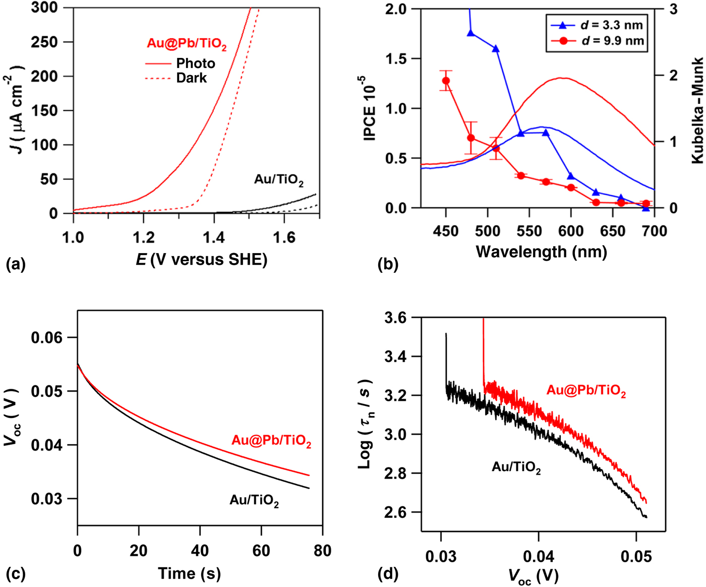
This section mainly describes our recent study on an Au-based bimetallic NP-SPEC cells for water splitting (Eq. 1). The overpotential of bulk-state metals for oxygen evolution reaction (OER) is in the order of Ni<Co<Cu<Pb<Pd<Pt<Au. Au has the largest overpotential, and thus, endowing NP with the catalytic activity for OER can improve the photocatalytic activity of Au/TiO2 for water splitting. We have recently shown that the performance of Au NP-SPEC cell for water splitting can be greatly improved by forming a Pb shell with a few atomic layer on the Au NP.[Reference Negishi, Naya, Kobayashi and Tada56] Three-electrode PEC cells with the structure of photoanode|0.1 M NaClO4 aqueous solution|Ag/AgCl|glassy carbon were fabricated using Au/TiO2 and Au–#Pb/TiO2 as the photoanode, and the current (J)–potential (E) curves were measured [Fig. 7(a)]. The Pb-shell formation gives rise to a dramatic increase in the photocurrent with a cathodic shift in the onset potential in the dark and under one-sun irradiation. In the IPCE action spectra for the Au/TiO2 photoanodes [Fig. 7(b)], the photocurrent rises at ~700 nm, while the λ edge for anatase TiO2 is ~390 nm. This spectral sensitization indicates that the Au–Pb/TiO2 photoanode operates via the hot-electron transfer (HET) mechanism, in which Au NPs act as the photosensitizer.[Reference Tian and Tatsuma62] The potential decay curves after interruption of visible-light irradiation was measured for two-electrode PEC cells with the structure of photoanode (Au/TiO2/FTO and Au–Pb/TiO2/FTO)|0.1 M NaClO4 aqueous solution|glassy carbon (cathode) under the open-circuit conditions. When the irradiation is interrupted, the photoinduced potential (E ph) decays toward the equilibrium value in the dark (E dark) with the back electron transfer from TiO2 to Au [Fig. 7(c)].[Reference Du, Furube, Yamamoto, Hara, Katoh and Tachiya63] The mean lifetime of the electrons injected into the CB of TiO2 from the sensitizer (τ n) was estimated as a function of V oc (=E ph–E dark) by analyzing the potential decay curve.[Reference Zaban, Greenshtein and Bisquert64] In the log (τ n/s) versus electrode potential (V oc/V) curve [Fig. 7(d)], the τ n for the Au–Pb/TiO2 system is much larger than that for the Au/TiO2 system at the same V oc. Thus, the Pb shell enhances the charge separation by suppressing the back electron transfer.
(a) Current (J)–potential (E) curves in the dark (dotted lines) and under visible-light irradiation (λ>430 nm, solid lines) for the Au/TiO2/FTO (black) and Au–Pb/TiO2/FTO (red) anodes. (b) IPCE action spectra for Au (d Au = 3.3 and 9.9 nm)/TiO2. (c) Photovoltage decay curves with turning off visible-light irradiation (λ>430 nm) for the Au/TiO2/FTO and Au–Pb/TiO2/FTO systems. (d) Plots of hot electron lifetime (τ n) in the Au/TiO2/FTO (black) and Au–Pb/TiO2/FTO (red) anodes as a function of photovoltage under open-circuit conditions (V oc). (Adapted/reproduced with permission from Ref. Reference Negishi, Naya, Kobayashi and Tada56, Wiley-VCH, 2017.)

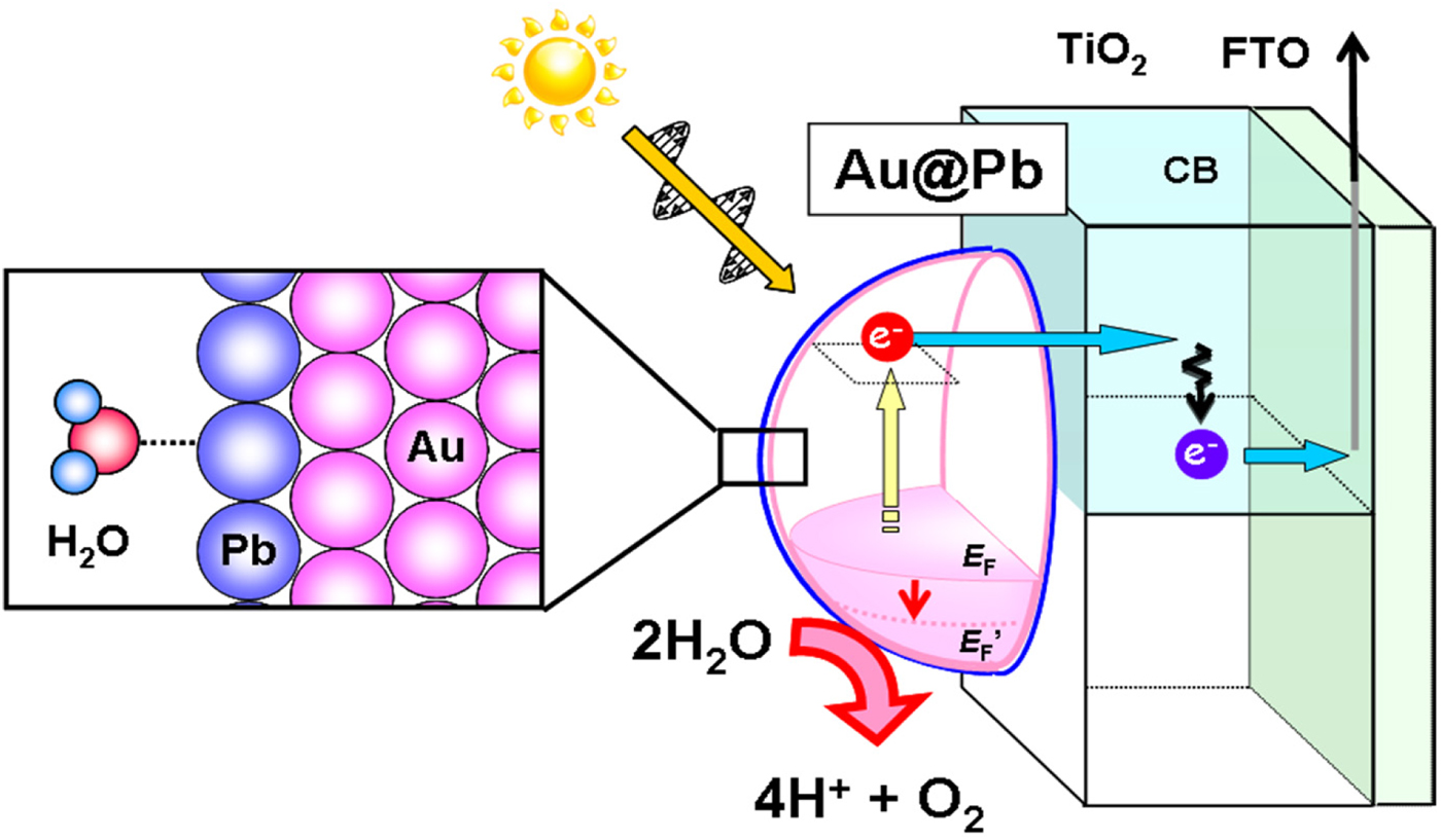
LSPR excitation of Au–#Pb/TiO2 gives rise to the HET from Au–Pb to TiO2 (Scheme 6). In this case, the Pb shell enhances the charge separation by suppressing the back electron transfer (ϕ inj↑). The electrons injected into TiO2 are finally transported to the Pt counter electrode through the external circuit, reducing water there. On the other hand, the lowering in the Fermi energy of the metal NP causes water oxidation on the surface, although the possibility of the direct water oxidation by the hot holes in the Au–Pb NP generated as the pair of hot electrons cannot be excluded. The Pb shell provides Au NP with a high catalytic activity for water oxidation (ϕ inj↑), whereas the shell formation of Ni with a low overpotential in the bulk state was ineffective. The striking Pb-shell effect unpredicted from the property for bulk-state Pb could stem from the unique interfacial structure and electronic state generated with the formation of HEPI junction.
Pb-shell catalytic effect on the performance of the Au–#Pb NP-SPEC cell for water splitting operating via the HET mechanism. (Adapted/reproduced with permission from Ref. Reference Negishi, Naya, Kobayashi and Tada56, Wiley-VCH, 2017.)

Summary and outlook
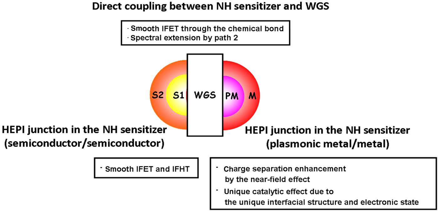
This article has described the nanoscale band engineering in the nanohybrid-sensitized photoanode of the PEC cells for H2 generation from water. The chemical aspect including the interfacial bonding, the heterojunction, and the influence of the composition of electrolyte solution is highlighted in addition to the physical aspect such as the electron confinement in semiconductor QDs and the plasmonic effects of Au NP (Scheme 7). The key in common with these nanohybrid sensitizers is the atomically commensurate junctions between the components, which enables the smooth photoinduced IFET and IFHT. The methodology should be widely useful for the design of the photoelectrodes and photocatalysts for the solar-to-chemical transformation and storage.
Interfacial effects in the nanohybrid-sensitized wide gap semiconductors (WGSs = TiO2, ZnO, etc.).

First of all, next subject is further development of the technologies for synthesizing nanohybrids with atomically commensurate junctions. Second, increasing the coverage of TiO2 by the photosensitizers as well as preparing large-area TiO2 (or other MO semiconductor scaffolds) is essential for increasing LHE and ϕ trans. Third, the development of the photoanodes widely responding to the visible-to-near-infrared light is also of great importance to improve the STHE through the increase in LHE. Thus, the hybridization of size- and shape-controlled Au NP and MX QD would be a very promising approach for further improvement in the STHE. Finally, the Pt-substitute cathode material should be developed to reduce the cell cost.
Acknowledgments
The author acknowledges Prof. Hisayoshi Kobayashi (Kyoto Institute of Technology) for DFT calculations, and Dr. Musashi Fujishima, Dr. Shin-ichi Naya, Takuya Ikeda, Ryo Akashi, and Kaoru Kitazono (Kindai University) for experimental supports and helpful discussion. This work was partially supported by a Grant-in-Aid for Scientific Research (C) No. 15K05654, and MEXT-Supported Program for the Strategic Research Foundation at Private Universities.