Introduction
Urea, which is major component, has been attracted interests for direct and/or microbial fuel cells as a ultimate sustainable and renewable biomass energy source.[Reference Lan and Tao1–Reference Kaneto, Nishikawa, Uto and Osawa7] The usefulness of urea was pointed out by Lan and Tao[Reference Lan and Tao1] in terms of the volumetric energy density, being about 1.6 times larger than the liquid H2. The issue in direct urea fuel cells is anode catalysts. Pt and rare metals are active to most of biofuels such as glucose and alcohol, however, they are inactive to oxidize urea at the anode.
We have studied conducting polymers such as polypyrrole (PPy), polyaniline (PANi), and poly(3,4-ethylenedioxythiophene)polystyrene sulfonate (PEDOT*PSS) to explore potentiality in biosensors[Reference Rajesh, Bisht, Takashima and Kaneto8] and biofuel cells.[Reference Kaneto, Nishikawa and Uto9, Reference Uto, Nishikawa and Kaneto10] PPy was found to be an excellent mediator to immobilize enzyme of urease to detect urea.[Reference Rajesh, Bisht, Takashima and Kaneto8] PANi and PEDOT*PSS exhibited catalytic activity for biomaterials of ascorbic acid and citric acid.[Reference Kaneto, Nishikawa and Uto9, Reference Uto, Nishikawa and Kaneto10]
Recently, Ni and Co compounds[Reference Lan and Tao1, Reference Nagao, Kobayashi and Hibino2, Reference Senthikumar, Kumar and Manthiram5] have been found to be effective catalysts for urea and urine. Direct urea fuel cells[Reference Lan and Tao1] with the structure of nano-sized Ni particle for anode and MnO2 for cathode catalysts with anion exchange polymer membrane demonstrated 14.2 mW/cm2 at the maximum power density. Ingenuity upon anion transport membrane and cathode catalyst enhanced the performance to 26.5 mW/cm2 at 300°C.[Reference Nagao, Kobayashi and Hibino2] The highest output power reported recently was 33.8 mW/cm2 using anode catalyst, Co3O4NiO and cathode catalyst, Co3O4MnO2 on carbon cloth fibers.[Reference Senthikumar, Kumar and Manthiram5]
We fabricated direct urea fuel cells using CuNi-plated polymer cloth, which played the role of anode catalyst and current collector.[Reference Kaneto, Nishikawa, Uto and Osawa7] CuNi cloth was woven with fine polyester fibers, therefore, resulting in substantially enormous surface area. It was found that the catalytic activity of the CuNi cloth was significantly enhanced by coating with the conducting polymer PEDOT*PSS. The maximum output power was obtained to be 1.88 mW/m2. This value was not larger than those of the reported values.[Reference Lan and Tao1, Reference Nagao, Kobayashi and Hibino2, Reference Senthikumar, Kumar and Manthiram5] However, the CuNi cloth and the membrane are commercially available, and the cells were operated at ambient temperature without circulation of fuel and air.
In this communication, it is mentioned that the performance of direct urea fuel cells is enhancement by the improvement of cell structure and materials. Fabrication of stacked cells to demonstrate lightening a light emitting diode (LED) is also reported.
Fabrication of cells
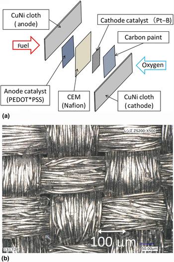
The cell structure shown in Fig. 1(a) is the core laminate,[Reference Kaneto, Nishikawa, Uto and Osawa7, Reference Kaneto, Nishikawa and Uto9, Reference Uto, Nishikawa and Kaneto10] being piled with CuNi cloth (anode)/PEDOT*PSS/cation exchange membrane (CEM)/Pt-black(Pt-B)/carbon paint/CuNi cloth (cathode). The anode is a fuel electrode, and cathode is an air (oxygen) electrode. Pt-B (High Spec. 1000) was purchased from Johnson Matthey Fuel Cells and used as a cathode catalyst. Nafion® (N117) was used as the CEM with the thickness of 188 µm.
(a) Structure of core laminates in direct urea biofuel cells. (b) Photographs of CuNi-plated polyester cloth.

CuNi-plated polyester cloth was obtained from SEIWA Electric Mfg. Co., Ltd. The photograph of surface morphology is shown in Fig. 1(b), consisting of woven fibers with the diameter of 10 µm. The large surface area is effective at enhancing the catalytic activity. The CuNi cloth was prepared by electroless Cu plating with the thickness of approximately 1–2 µm, followed by electrodeposition of Ni by the thickness of 0.1~0.3 μm. The surface resistivity was 0.05 Ω/□. Modification of piling materials was also tested to confirm the functional effect of materials. For instance, carbon sheet (C-sheet), TGP-H-060 from Chemix Co., Ltd. was used instead of carbon paint. A stainless steel mesh (SUS316 #200; anticorrosive electrode) was also employed as the replacement of CuNi cloth for the current collector.
The Pt-B was spread on the CEM with approximately 2 mg/cm2 for the active area of 1 × 1 cm2. Carbon paint (Aquadag, Acheson) was coated on the back side of CuNi cloth (cathode) to make good contact with Pt-B. Ni also was plated on C-sheet by the typical condition of 2 mA/cm2 for 1 h as the anode catalyst. Water emulsion of PEDOT*PSS was painted on CuNi cloth and Ni-coated C-sheet by typically 2–3 mg/cm2. The concentration of urea was 0.5 M water solution, and the volume of fuel tank was 0.24 cm3. The urea of extra pure reagent (purity >99.0%) was purchased from Nakarai Tesque and used without further purification. The cells were tested under ambient conditions of approximately 22°C and humidity of 40%–60%. The experimental setup and characterization of fuel cells were described in our previous papers.[Reference Kaneto, Nishikawa, Uto and Osawa7, Reference Kaneto, Nishikawa and Uto9, Reference Uto, Nishikawa and Kaneto10]
Results and discussion
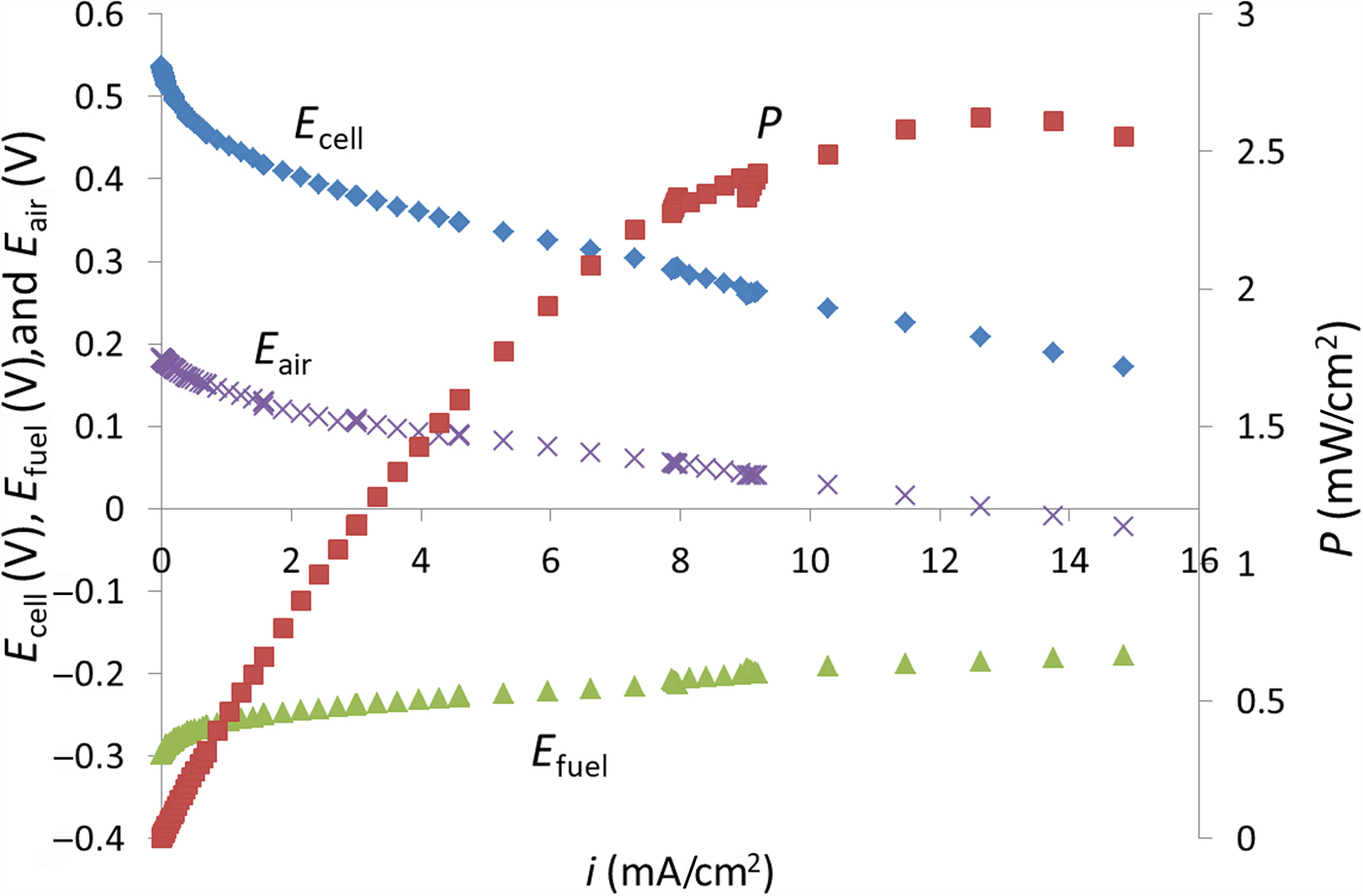
Figure 2 shows typical output characteristics (polarization curves) in a direct urea fuel cell for the cell configuration, #B in Table I. The cell voltage, E cell (V); electric power, P (mW/cm2); potentials at fuel electrode, E fuel (V); and air electrode, E air (V) against a reference electrode of Ag+/Ag0 are shown as a function of the current density, i (mA/cm2). E cell is given by E air − E fuel, and P = E cell × i.
Typical polarization curve in a direct urea fuel cell (#B) obtained for 0.5 M urea and CuNi cloth coated with PEDOT*PSS.

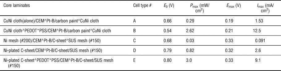
Summary of cell performances of E 0, P max, E max, and I max in various core laminates of direct urea fuel cells

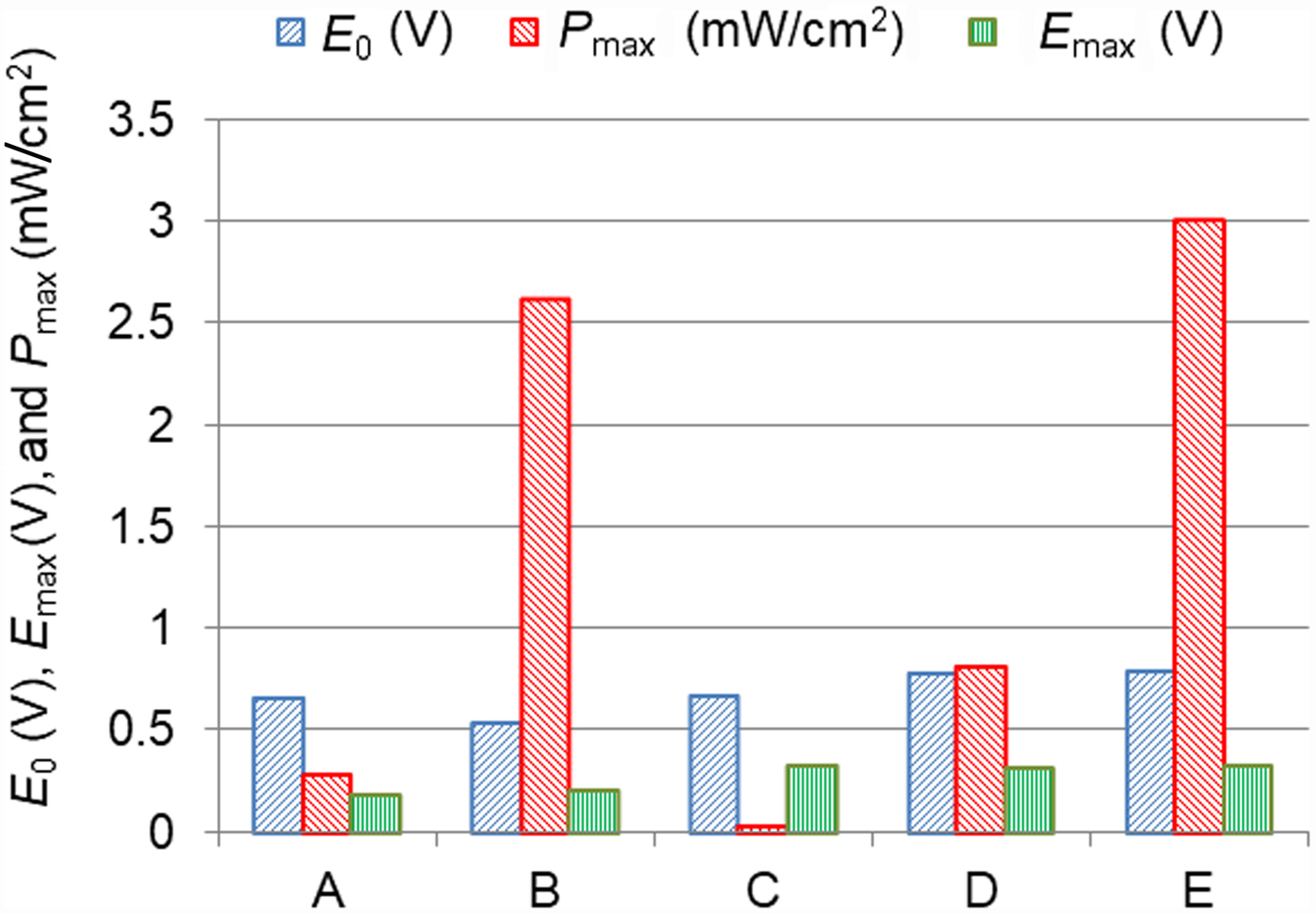
The E cell dropped steeply at the beginning of current increase as shown in Fig. 2, which was usually observed and due to the decrease of E fuel and E air, namely, polarization at electrode surfaces. Cell performances in various cell structures (core laminates) are summarized in Table I, where E 0 is the electromotive force (open circuit voltage), P max is the maximum power density, E max and I max are the E cell and current density at the maximum power, respectively. To visualize the cell performance bar graphs in various core laminates are depicted in Fig. 3.
Comparison of cell performances in various core laminates.

The P versus i curve represents a parabolic curve[Reference Kaneto, Nishikawa and Uto9, Reference Uto, Nishikawa and Kaneto10]; P = −ri 2 + Ei, where r is the internal resistance and E is the cell potential, respectively. Best fitting of P versus i to the experimental curve for the cell, #B gave E = 0.43 V and r = 18 Ω/cm2. These values are approximately consistent with the values of E 0 and r = E max/I max, as shown by #B in Table I. The typical maximum current, which is basically twice that of I max, was about 20 mA/cm2.
The cell type #A indicates that CuNi cloth alone catalyzed urea at an appreciable level and served as the current collector. It is interesting to note that coating the CuNi cloth with PEDOT*PSS enhanced remarkably the catalytic activity by ten times as shown by #B in comparison with #A in Fig. 3. The results of #A and #C demonstrated that CuNi cloth was superior to Ni mesh, because of large surface area in CuNi cloth. Comparison of #A and #D indicated that plating of Ni on the C-sheet gave better performance than that of CuNi cloth, probably suggesting that C-sheet could be more porous than the CuNi cloth or some other reasons. It should be noted that using C-sheet and SUS mesh for the cathode current collector resulted in better performance in power and cell voltage than those of carbon paint and CuNi cloth, as shown in Fig. 3. The results were associated with that leakage and/or crossover of urea through CEM fell off the cathode activity at the CuNi cloth current collector. Hence, the cell #E demonstrated the best performance.
It was observed that a cell with C-sheet alone for the anode material showed E 0 = 0.4 V and P max = 0.5 µW/cm2, and that with PEDOT*PSS coated C-sheet exhibited E 0 = 0.3 V and P max = 8 µW/cm2, indicating that these materials were not effective for anode catalyst. Long-term immersion of CuNi cloth in 0.5 M urea did not result in corrosion or degradation of CuNi for a month, indicating CuNi cloth is stable in urea. The results mentioned above indicate that Ni plays the major role of the catalyst in urea fuel cells and combination with PEDOT*PSS enhances the catalytic activity for urea.[Reference Kaneto, Nishikawa, Uto and Osawa7] The detailed role of PEDOT*PSS is not known, however, may be due to the polymeric structure of conjugated π electrons, which could be fitted to oxidized biofuels energetically and spatially. And also loose packing of polymer structure should allow penetration of urea molecules inside the film.
The anode reaction should be complicated, however, we proposed a possible reaction by the overall reaction (1) with four electron transfer[Reference Kaneto, Nishikawa, Uto and Osawa7]:
 $${\rm CO(N}{\rm H}_{\rm 2}{\rm )}_{\rm 2} +\ {\rm4}{\rm O}_{\rm 2}\to {\rm C}{\rm O}_{\rm 2} +{\rm\ 2HN}{\rm O}_{\rm 3}{\rm +} {\rm H}_{\rm 2}{\rm O}{\rm.} $$
The production of nitric acid (HNO3) was associated with the observation that long-term operation resulted in etching of Ni on CuNi cloth but not Cu. Alternatively, however, ionization of Ni due to the oxidative force through the cathode reaction may not be excluded. The cell potential[Reference Kaneto, Nishikawa, Uto and Osawa7] was estimated from reaction (1) to be 0.86 V, which was slightly larger but nearly coincided with the observed E 0 in #D and #E in Table I. E 0 should depend on the redox mechanisms of fuel and catalyst activity, as well as crossover of fuel and oxygen through membrane. Moreover, there should be the other intermediate products such as nitrogen oxides NOx, NH3, and so on besides (1). Furthermore, the possibility of Ni ionization and consumption is not entirely excluded. The purity of fuel may be also another important issue for practical use of urine fuel cells. We do not discuss the details at the present stage until the analysis of reaction products in the fuel solution. These will be done in a future study.
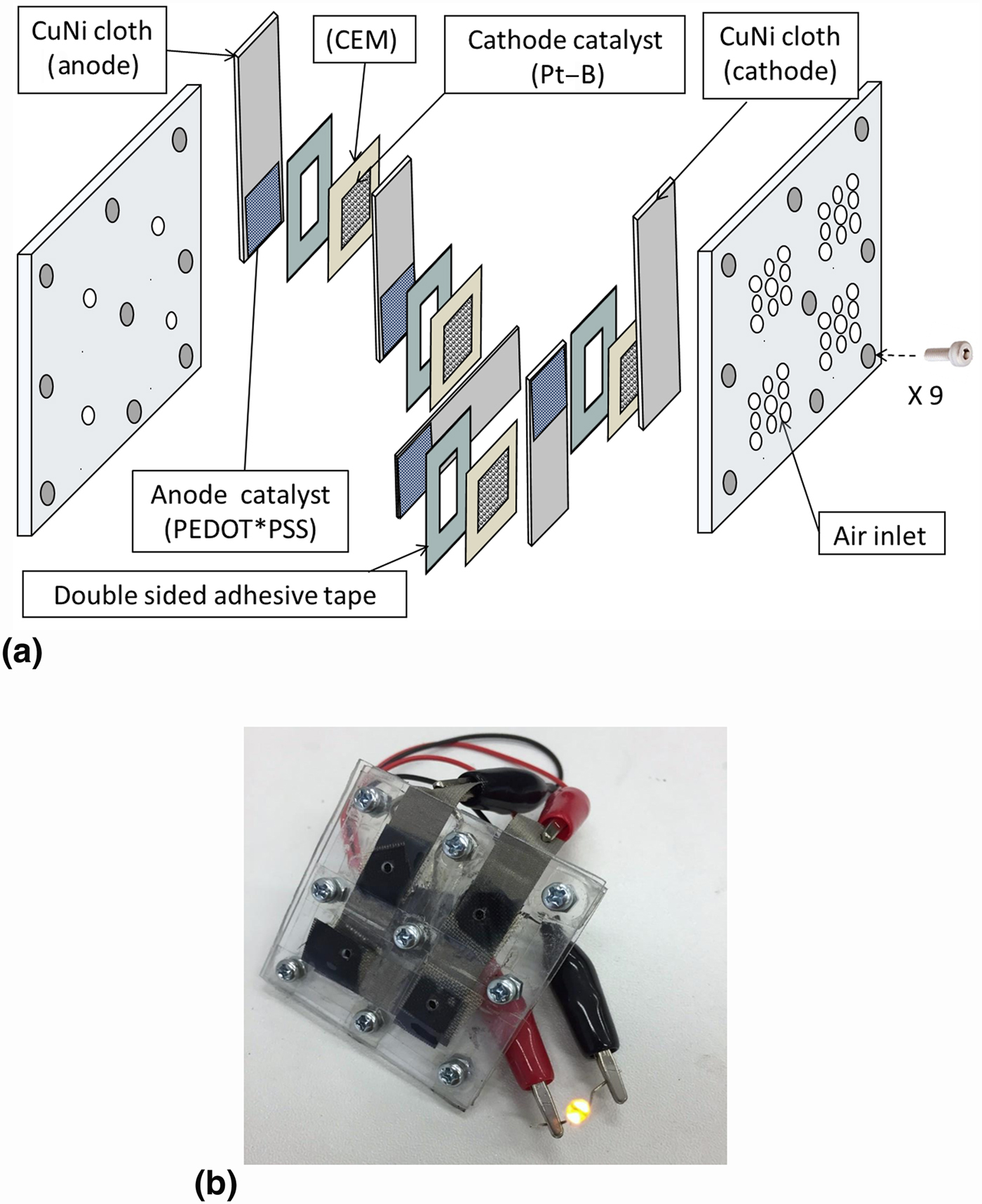
Figure 4(a) shows schematic drawing of stacking four cells (type #B) to elevate the output voltage (approximately 2.2 V) for lightening LED. The voltage to turn on an orange LED requires more than 2 V and the current of larger than 0.1 mA. The voltage depends on the color of LEDs. The lightening of an orange LED is demonstrated in Fig. 4(b). The LED lasted lightening for about 3 h with 0.05 cm3 of 0.5 M urea water solution.
(a) Assembly of stacking four cells to lighten an LED. (b) Demonstration of lightening of an orange LED.

Summary
Direct urea fuel cells were fabricated using CuNi-plated polymer cloth as the anode catalyst, which served also as current collectors. The cell performance was remarkably enhanced by coating CuNi cloth with the conducting polymer of PEDOT*PSS. The cell was further improved by using Ni-plated C-sheet and PEDOT*PSS. A possible scheme of the reaction in direct urea fuel cells was proposed and the mechanism of catalyst was discussed. Further studies on the detailed mechanism of catalytic reaction by CuNi, the role of conducting polymers, and stability of cells will be continued.
Acknowledgments
The authors would like to express their sincere thanks to Prof. Hidenori Okuzaki, Yamanashi University, for the supply of PEDOT*PSS. The research was supported by the JSPS KAKENHI with the grant number of 16K06280.