Introduction
With the development of wireless communications, spectral resource requirements have become increasingly important. The contribution of cognitive radio and the use of reconfigurable antennas made it possible to optimize the use of the electromagnetic spectrum [Reference Hall, Gardner, Kelly, Ebrahimi, Hamid, Ghanem, Herraiz-Martinez and Segovia-Vargas1, Reference Hamid, Gardner, Hall and Ghanem2]. Users can now use the other unused frequency bands at a time t in the day in addition to dedicated bands without harming the primary users of these bands, allowing better spectrum resource management and a high level of quality service regardless the time of the day. In addition, the use of reconfigurable antennas has made it possible to introduce functionalities directly at the antenna (signal processing antennas) and better flexibility in frequency compared with conventional antennas (fixed operating frequency). The reconfigurable antennas used in the cognitive and multiservice radios applications are classified in three categories according to the functionalities they propose. The first category is the frequency reconfiguration in which we find: frequency switching; the reconfiguration is discontinuous and is done using switches like pin diodes and MEMS [Reference Borhani, Rezaei and Valizade3–Reference Mansoul and Ghanem8]. The second type is the frequency tuning in which the operation frequency is adjusted continuously. Generally, components such as variable capacities with the applied tension (varicap diodes) are used for the reconfiguration [Reference Idris, Hamid, Jamaluddin, Rahim and Kelly9–Reference Zhu, Holtby, Ford, Tennant and Langley12]; another type consists of filtering frequency bands within a large band of operations (notched band) [Reference Badamchi, Nourinia, Ghobadi and Shahmirzadi13–Reference Oraizi and Valizade Shahmirzadi15]. The second category is the radiation pattern reconfiguration, which modifies the antenna radiation pattern, and controls the direction of radiation and thus focuses the maximum radiated power in a particular direction [Reference Sen and Guy16–Reference Alam and Abbosh19]. The third category is the polarization reconfiguration; the antenna switches between different polarization modes (circular right, circular left, horizontal, vertical) [Reference Dinesh Kumar, Binod Kumar, Santanu and Ganga Prasad20–Reference Chow-Yen-Desmond, Yan-Jie and Hen-Lun23]. In the literature, it is also possible to find antennas with two reconfigurable functions at the same time, for example, the radiation pattern and frequency reconfiguration or frequency and polarization reconfiguration [Reference Li-Rong, Rui-Xin and Yin24–Reference Liang, Sanz-Izquierdo, Parker and Batchelor27].
In this article, we propose a new approach to design reconfigurable antennas suitable for cognitive radio applications. This antenna can operate in four different modes, an ultra-wide band (UWB) mode for sensing the spectrum environment, and for the operation, three narrow band modes, two mono-band modes, and one dual-band mode. To achieve this, modifications were introduced to the structure of the basic antenna (UWB antenna without filtering in the ground plane) by the addition of a filter consisting of four slots; the location and the electrical length of the slots have been carefully chosen to have the best performance in terms of operating frequency and impedance matching at −10 dB. The principle of reconfiguration consists in using switches to modify the distribution of the antenna surface currents in the ground plane in order to achieve the desired radio-electric properties (frequency and radiation patterns). To demonstrate our approach and feasibility, we have used ideal switches as a means of reconfiguration. The on/off state of the switch is modeled by the presence/absence of a perfect conductive strip (PEC), respectively. It is important to mention that the use of ideal models should not be seen as an obstacle to the validity of the proposed approach since real switches have been successfully used on similar structure in [Reference Mansoul, Ghanem, Hamid and Trabelsi7]. During the design phase, we targeted the usual and widely used operating bands such as WiFi, WiMax, and UWB. The use of two independent slots in the middle of the ground plane of the antenna makes it possible to have a dual-band operation mode in the two bands of WiFi and WiMax at 2.4 and 3.5 GHz, respectively, and at the same time. Of course, the proposed approach could be used to design antenna with more bands by integrating other slots with different lengths.
Antenna design and study
Proposed antenna geometry
Figure 1 shows the geometry of the proposed antenna with and without modifications. It is designed on FR-4 substrate with a permittivity of 4.3, a thickness of 1.6 mm, and loss tangent of 0.018. The values of the optimized geometrical parameters illustrated in Fig. 1 are: L = 84 mm, W = 84 mm, L g = 32.25 mm, L 1 = 63 mm, L 2 = 21 mm, L 3 = 41.7 mm, L 4 = 26.7 mm, W feed = 2.9 mm, W slot = 1.8 mm, y 1 = 2.45 mm, y 2 = 23.85 mm, x 1 = 5.6 mm, r 1 = 23.25 mm, r 2 = 26.5 mm, h s = 1.6 mm, h 1 = 25.35 mm, h 2 = 18.225 mm, h 3 = 14.475 mm, h 4 = 11.1 mm, d 1 = 6.5 mm, d 2 = 7.2 mm, d 3 = 5.7 mm, and d 4 = 15.7 mm.
Geometry of the proposed antenna with highlighted dimensions (a) before the modifications, (b) proposed reconfigurable antenna after the modifications.

Filter implementation
The starting structure used for the design of the reconfigurable antenna is a conventional UWB monopole antenna. The antenna is composed of an elliptical-shaped radiating main element fed by a 50 Ω microstrip line on the top facade of the substrate and a ground plane of dimensions 84 mm × 32.25 mm, on its bottom facade as shown in Fig. 1(a). In order to introduce the proposed reconfiguration mechanism, four horizontal slots have been etched into the ground plane of the antenna as shown in Fig. 1(b). Each of the slots has a specific function; the two slots at the top and bottom of the ground plane which are placed symmetrically with respect to the y-axis are used to fully filter the frequencies between 1.5 and 6 GHz (124%) as shown in Fig. 2.
Simulated reflection coefficient of the antenna with and without upper and bottom slots.

The slot at the bottom filters the higher frequencies (low-pass filter) of the UWB band, and the slot at the top filters the lower frequencies of the UWB band (high-pass filter). The two other slots located in the middle of the ground plane (on the left and the right) are used to create poles in the filter response, which allows creating new operating bands at frequencies proportional to their electrical lengths (λ/2) as shown in Fig. 3.
Simulated reflection coefficient of the antenna with one slot with different length in the middle.

In this case, the filter passes only waves that have a wavelength proportional to the electrical length of the two slots, to be radiated by the elliptical-shaped main element; all other frequencies are filtered (blocked). In the proposed design, the slot lengths are chosen to create new frequency bands at 2.4 and 3.5 GHz, which correspond to WiFi and WiMax, respectively.
In order to introduce frequency reconfiguration, seven switches are used to switch between the modes of operation of the antenna, four located on the upper and lower slots; they are placed symmetrically on the slots to decouple the two slots from the microstrip feed line, and thus restore the starting operating mode of the antenna (monopole without filter). For switches on the two slots in the middle of the ground plane (on the right and the left), they are placed so as to decouple the two slots from the feed line and also reduce the coupling between the existing slots. The role of the switches is to activate/deactivate the slots and thus the filtering effect. In the perception mode (UWB mode), all the switches are turned on, as shown in Fig. 4(a), which causes the deactivation of all slots, and the antenna retrieves its UWB behavior. In the dual-band operation mode, all the switches (S1–S7) are turned off which corresponds to Fig. 4(b). The mono-band cases correspond to Figs 4(c) and 4(d), where the switches of one of the two slots in the middle are turned on. It is worthwhile mentioning that due to the length of the right-hand middle slot (Fig. 4(d)), two switches are needed to deactivate it. The configurations of switches for the four operating modes are resumed in Table 1. The entire simulation process was performed using the CST Microwave Studio software.
Ideal switches implementation for the four modes (on/off state of the switch is modeled by the presence/absence of PEC).

Switches configuration for the four cases

The resulting antenna is capable of switching between an UWB mode (124%) to three narrow band modes, two in single-band mode at 2.4 GHz (6%) and 3.5 GHz (5%) and one in dual-band mode as shown in Fig. 5.
Simulated reflection coefficient of the proposed antenna in the four operating modes.

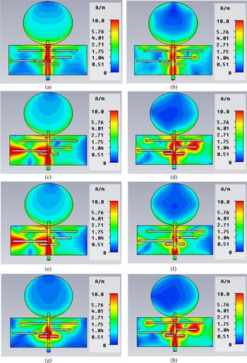
In order to better understand the operation of the filter and the antenna, a study on the surface current distribution was carried out. Figure 6 shows the current distribution for UWB mode, dual band, WiFi, and WiMax, respectively.
Surface current distribution of the antenna: (a) UWB mode at 2.4 GHz, (b) UWB mode at 5.2 GHz, (c) dual band at 2.4 GHz, (d) dual band at 3.5 GHz, (e) WiFi mode at 2.4 GHz, (f) WiFi mode at 3.5 GHz, (g) WiMax mode at 2.4 GHz, and (h) WiMax mode at 3.5 GHz.

Figs 6(a) and 6(b) show the surface current distribution of the antenna for the UWB mode at 2.4 and 5.2 GHz, respectively. For both frequencies, there is a current concentration in the feed line and the area between the main radiating element (elliptical structure) and the ground plane; the antenna radiates like a conventional UWB monopole (the filter is disabled). Figs 6(c) and 6(d) show the surface current for the dual-band mode at 2.4 and 3.5 GHz, respectively; we can see a high level of current distribution on the two middle slots, the right slot at 3.5 GHz and the left slot at 2.4 GHz.
For the WiFi mode (Figs 6(e) and 6(f)), there is a high current concentration on the left middle slot, which has an electrical length proportional to the wavelength of the WiFi. We can see also that the effect of the second slot at 3.5 GHz (Fig. 6(f)) is deactivated (S7 is turned on) and there is a current distribution on the slot; the filter passes only the WiFi frequencies, to be subsequently radiated by the main radiating element. For the WiMax mode (Figs 6(g) and 6(h)), there is a current concentration on the right middle slot, which has an electrical length proportional to the wavelength of the WiMax. We can see also that the effect of the second slot at 2.4 GHz (Fig. 6(g)) is deactivated (S5 and S6 are turned on) by comparison to dual-band mode; the filter passes only the WiMax frequencies.
Experimental results and discussions
The antenna has been fabricated and measured with a vector network analyzer. Figure 7 shows a photograph of one of the prototypes realized with ideal switches (UWB mode). Superposed simulated and measured reflection coefficients are shown in Fig. 8 in separated curves for more clarity. The experimental results obtained clearly show the ability of the antenna to operate in different modes (mono-band, dual-band, and UWB). The measurement results show a decent agreement with those of the simulation in the four cases, with a good adaptation to −10 dB. We can also see some discrepancies between the simulated and measured results, especially for the UWB case, which could be explained by manufacturing tolerances (misalignment of both sides of the antenna) and also by the uncertainty in the thickness and/or the dielectric constant of the FR4-epoxy substrate. To demonstrate this for the UWB case, the antenna has been simulated by taking the spacing between the center of the radiating element of elliptical form and the ground plane of the antenna y 2 = 25.35 mm, and the obtained result was in better agreement with the measurements as shown in Fig. 9.
Realized prototype with ideal switches (UWB).

Measured and simulated reflection coefficients of the proposed antenna.

S 11 of the UWB mode with y 2 = 25.35 mm compared with the measurement result.

Figure 10 shows the superimposed realized gain of the proposed antenna for the four cases. The maximum gain at 2.4 and 3.5 GHz is about 4 and 4.5 dB, respectively. In the UWB case, the gain increases with the frequency. The maximum gain is obtained at 5.8 GHz with a value of 5.5 dB. It can be noted also that compared with the UWB mode, the use of the antenna in one of the narrowband modes provides close gain performance or even better. However, outside the operating band, the reconfiguration does provide gain suppression that could exceed 10 dB at some frequencies, which could justify the cost associated with the use of the switches.
Realized gain of the proposed antenna.

Figs 11 and 12 show the measured and simulated radiation patterns of the proposed antenna for different cases in the E- and H-planes, respectively. The measurement results show that the proposed antenna has an omnidirectional radiation pattern in the H-plane and bidirectional radiation in the E-plane for the UWB mode (at 2.4 GHz). For WiFi and WiMax modes, the antenna has directional radiation patterns.
Radiation patterns of the proposed antenna in the E-plane.

Radiation patterns of the proposed antenna in the H-plane.

Conclusion
In this work, a multi-selective frequency reconfigurable antenna capable of switching between an UWB operating mode and three selective narrow band modes, two in single band at 2.4 GHz (WiFi) and 3.5 GHz (WiMax) and one in dual band, has been presented and demonstrated. The measured data compared with those of simulation showed good performance and an acceptable agreement. While the presented work uses the presence/absence of a PEC to model real switch operation, it is believed that the obtained results conjugated with the previous work using real switches on a very similar structure allow validating approach. The proposed design approach is potentially for use in wireless communication systems such as cognitive radios.
Acknowledgement
The authors would like to thank the Laboratoire de Recherche Télébec en Communications Souterraines (LRTCS), Val-d'Or, Canada (particularly Prof. Mourad NEDIL and M. M. L. SEDDIKI) for their helps during the measurements of the fabricated prototypes.
 Ali Mansoul received his Engineering degree in Electronics from the University of Jijel, Algeria, in 2006, his M.Sc. degree in Telecommunications from Polytechnic School of Bordj El Bahri, Algiers, Algeria, in 2010, and his Ph.D. degree in Telecommunications from the National Polytechnic School of Algiers, in 2016. Currently, he is a Researcher and Head of the Antennas Group at Centre de Developpement des Technologies Avancees (CDTA), in Baba Hassen, Algiers, Algeria. His research interests include compact microstrip antennas design, reconfigurable antennas, antennas for MIMO systems, wearable antennas, and RF circuits.
 Farid Ghanem received his Bachelor degree from the Electronics Engineering Department of Ecole Nationale Polytechnique in Algiers, Algeria, and he got his M.Sc. and PhD degrees in Telecommunications from the National Institute of Scientific Research in Montreal, Canada. He joined The University of Birmingham in Birmingham, UK, as an Honorary Research Fellow before joining The University of Sheffield as a Research Associate and then the Prince Mohammad Bin Fahd University in Al-Khobar, Saudi Arabia, as an Assistant Professor. In October 2011, he joined the Centre de Developpement des Technologies Avancees (CDTA) in Baba Hassen, Algiers, Algeria, where he held the position of Director of the Telecom Division and the Head of the Antennas Team. In September 2016, he joined Brandt Group of Cevital Group as R&D&I Telecom Product Director. His research interests are in antenna design where he works on developing new antennas with advanced properties for new applications such as cognitive radios, wireless sensors, IoT, MIMO systems.