1. Introduction
Early applications of microfluidics often combined multiple fluid streams under conditions of laminar flow, with applications ranging from flow cytometry (Eyal & Quake Reference Eyal and Quake2002) to micro-reactors (Kenis, Ismagilov & Whitesides Reference Kenis, Ismagilov and Whitesides1999). In these systems, moderate Reynolds numbers (
 $Re<3000$
) inhibit turbulent flow, ensuring that fluids mix only due to molecular diffusion. Further, Stokes flow is often assumed, allowing boundary layer analyses to describe some aspects of mixing (Ismagilov et al.
Reference Ismagilov, Stroock, Kenis, Whitesides and Stone2000; Sprague & Dutta Reference Sprague and Dutta2012; Thorson et al.
Reference Thorson, Brushett, Timberg and Kenis2012; Braff, Bazant & Buie Reference Braff, Bazant and Buie2013a
; Braff, Buie & Bazant Reference Braff, Buie and Bazant2013c
). In practice, the Reynolds number in many of these devices is of order unity or greater. As long as the flow is fully developed and unidirectional, this is irrelevant since the velocity and the velocity gradient are orthogonal, eliminating inertial effects. However, when the flow bends, or if two channels converge into one, these effects no longer disappear, and must be taken into account.
The role of inertia in microfluidics has been previously examined in the context of flow in curved channels (Dean Reference Dean1927; Berger, Talbot & Yao Reference Berger, Talbot and Yao1983; Di Carlo Reference Di Carlo2009; Mao et al. Reference Mao, Nawaz, Lin, Lapsley, Zhao, McCoy, El-Deiry and Huang2012; Norouzi & Biglari Reference Norouzi and Biglari2013). Asymptotic expansions have been calculated for very specific cases, including flow in a curved rectangular channel (Norouzi & Biglari Reference Norouzi and Biglari2013), but most efforts have been numerical (Guglielmini et al. Reference Guglielmini, Rusconi, Lecuyer and Stone2010) or experimental (Van Hirtum, Grandchamp & Cisonni Reference Van Hirtum, Grandchamp and Cisonni2012). There has also been some investigation of geometrically induced inertial recirculation created by sharp corners that lead to flow separation (Chiu Reference Chiu2006; Sudarsan & Ugaz Reference Sudarsan and Ugaz2006). Inertia has also been identified as playing a role in common inlet geometries where multiple streams converge, but questions remain (Gambin et al. Reference Gambin, Vandelinder, Ferreon, Lemke, Groisman and Deniz2011; Nasir et al. Reference Nasir, Mott, Kennedy, Golden and Ligler2011). In this work, we examine the role of inertia around the inlet of two channels coming together under a range of conditions, taking existing experimental inlet designs used in membraneless electrochemical cells as a template (Jayashree et al. Reference Jayashree, Gancs, Choban, Primak, Natarajan, Markoski and Kenis2005, Reference Jayashree, Yoon, Brushett, Lopez-Montesinos, Natarajan, Markoski and Kenis2010; Salloum & Posner Reference Salloum and Posner2010; Braff et al. Reference Braff, Bazant and Buie2013a ; Braff, Buie & Bazant Reference Braff, Buie and Bazant2013b ). These systems rely on reactant separation to successfully generate power. Fully developed unidirectional flow ensures reactant separation, but the extent to which this assumption breaks down near the inlet is not well understood, and has not been considered in past investigations of membraneless electrochemical systems (Braff et al. Reference Braff, Buie and Bazant2013b ).
In this work, the Navier–Stokes equations are solved numerically for two- and three-dimensional geometries describing the flow of a fluid introduced into a main channel via an angled inlet. The geometry of this system mimics that of a membraneless laminar flow battery presented experimentally elsewhere (Braff et al.
Reference Braff, Bazant and Buie2013a
). Two major sources of mixing are identified: recirculation at the inlet junction due to flow separation, and fluid mixing perpendicular to the flow direction due to three-dimensional wall effects. We find that under certain conditions, these two effects drastically increase mixing beyond what would be predicted in a fully developed unidirectional system. A number of mitigation strategies are presented and discussed, and a scaling analysis is performed to better understand the underlying physics. To our knowledge, the scaling analysis herein is the first attempt to predict the onset of separation and secondary flows at the intersection of microchannels at moderate
 $Re$
.
2. Numerical solution
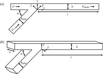
Two- and three-dimensional domains were modelled, as shown in figure 1. The fluid flow was modelled using the Navier–Stokes equation, and mass transport was overlaid onto the results of that solution using dilute solution theory in a Newtonian fluid. The complete set of governing equations solve for the velocity field
 $\boldsymbol{v}$
, pressure
 $P$
, and concentration
 $c$
in terms of fluid density
 ${\it\rho}$
, viscosity
 ${\it\mu}$
, and diffusion coefficient
 $D$
:
 $$\begin{eqnarray}\displaystyle & \displaystyle {\it\rho}\left(\frac{\partial \boldsymbol{v}}{\partial t}+\boldsymbol{v}\boldsymbol{\cdot }\boldsymbol{{\rm\nabla}}\boldsymbol{v}\right)={\it\mu}{\rm\nabla}^{2}\boldsymbol{v}-\boldsymbol{{\rm\nabla}}P, & \displaystyle\end{eqnarray}$$
 $$\begin{eqnarray}\displaystyle & \displaystyle \frac{\partial c}{\partial t}+\boldsymbol{v}\boldsymbol{\cdot }\boldsymbol{{\rm\nabla}}c=D{\rm\nabla}^{2}c. & \displaystyle\end{eqnarray}$$
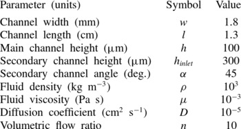
The system was implemented in COMSOL Multiphysics (Burlington, MA). The flow remains laminar because the Reynolds numbers investigated were sufficiently low. Numerical parameters were chosen to match previous experimental data, and unless otherwise specified are listed in table 1. To be consistent with past experimental work, the volumetric flow ratio
 $n$
between the inlet to the main channel and the inlet to the secondary channel was maintained at 10:1, with a dimensionless concentration of one maintained at the beginning of the secondary channel. The flow rates were set to ensure that once the channels converged, the average flow velocity in the main channel,
 $U_{main}$
, resulted in the specified Reynolds number, expressed in terms of the fluid density
 ${\it\rho}$
, fluid viscosity
 ${\it\mu}$
, and channel height
 $h$
:
 $$\begin{eqnarray}\displaystyle Re=\frac{{\it\rho}U_{main}h}{{\it\mu}}. & & \displaystyle\end{eqnarray}$$
Flow cell geometry in the (a) two-dimensional and (b) three-dimensional domain.

Parameters employed in the numerical calculation unless otherwise specified.

3. Results and discussion
It is useful to compare the numerical results with those assuming fully developed unidirectional flow. In this case species transport is modelled by assuming unidirectional Poiseuille flow in a channel with perfectly divided reactant starting at
 $x=0$
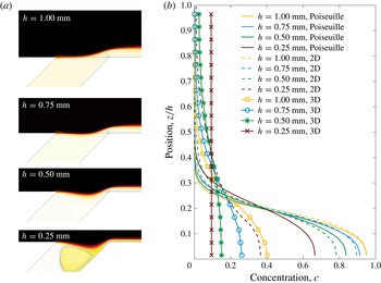
in the channel, as might be ideally assumed for the geometry shown in figure 1. In such a system, the reactant concentration profile at the inlet of the channel could be assumed to be an idealized step function, while the flow could be treated as perfectly unidirectional Poiseuille flow. Under these idealized conditions, there would be no advection of reactant across the channel, and reactant diffusion across the channel is sufficiently slow that almost none of it reaches the opposite side of the channel by the time it reaches the outlet, as shown in figure 2. This condition is necessary for a number of applications, and would indicate that if inertial effects can be neglected, channel heights as small as
 $250~{\rm\mu}\text{m}$
are feasible.
(a) Species concentration distribution and fluid stream lines for two-dimensional flow near the inlet as a function of channel height for a Reynolds number of 10. All other parameters are specified in table 1. For sufficiently thin channels, flow separation and recirculation can be observed. (b) Species concentration at the main channel outlet (
 $x/L=1$
) centreline as a function of channel height for fully developed Poiseuille flow, a two-dimensional inlet, and a three-dimensional inlet geometry with other parameters as specified in table 1. In the absence of flow recirculation, the two-dimensional model produces results similar to those predicted by ideal Poiseuille flow, but recirculation significantly enhances mixing. The three-dimensional channel produces significantly more mixing, with significant mass reaching the far wall for channels as tall as
 $500~{\rm\mu}\text{m}$
.

Two-dimensional numerical calculations were performed for a range of channel heights, from 1 mm down to
 $250~{\rm\mu}\text{m}$
, as shown in figure 2. For channel heights greater than
 $500~{\rm\mu}\text{m}$
, the fluid from the secondary channel appears to flow smoothly into the main channel, with minimal disturbance in the flow near the inlet. This results in strong species separation at the outlet of the channel consistent with the fully developed case. As the channel height shrinks to
 $500~{\rm\mu}\text{m}$
, however, significant flow deformation is observed in the inlet. At
 $250~{\rm\mu}\text{m}$
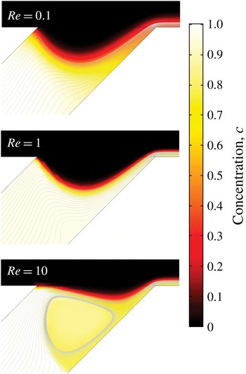
, flow recirculation is observed in the secondary channel, resulting in dramatically increased mixing, and diminished species separation at the outlet of the main channel. This recirculation behaviour is a function of the Reynolds number in the system, indicating that it is inertial in nature, as shown in figure 3. This type of steady recirculation behaviour is also commonly observed in flow along curved surfaces when the Reynolds number is between 4 and 40 (Kundu, Cohen & Dowling Reference Kundu, Cohen and Dowling2012).
Species concentration near the inlet of the two-dimensional channel with a height of
 $250~{\rm\mu}\text{m}$
as a function of Reynolds number. Under the conditions specified in table 1, Reynolds numbers of 0.1, 1, and 10 correspond to effective inlet Reynolds numbers of 0.3, 3, and 30, respectively. As the Reynolds number increases, the velocity gradient near where the secondary channel meets the main channel is enhanced, resulting in flow deformation and recirculation.

Greater understanding of the physics leading to recirculation can be gained by considering the motion of fluid through the secondary channel towards the main channel. As the fluid nears the intersection, it is accelerated by the main channel flow. We postulate that as the flows increase in velocity and the inertia of the main channel flow becomes more important, the dynamic pressure of the main channel flow is sufficient to distort the fluid in the secondary channel upwards away from the bottom of the channel. This in turn drives recirculation and causes mixing to occur. This parameter amounts to an effective Reynolds number for the inlet region that is distinct from the Reynolds number for fluid flow in the main channel defined in (2.2). The characteristic velocities
 $U^{\prime }$
in the secondary channel and
 $U$
in the main channel can be expressed in terms of the main channel Reynolds number and the parameters listed in table 1:
 $$\begin{eqnarray}\displaystyle & \displaystyle U=\frac{n}{1+n}\frac{{\it\mu}Re}{{\it\rho}h}, & \displaystyle\end{eqnarray}$$
 $$\begin{eqnarray}\displaystyle & \displaystyle U^{\prime }=\frac{1}{1+n}\frac{{\it\mu}Re}{{\it\rho}h_{inlet}}. & \displaystyle\end{eqnarray}$$
 $x$
direction can be performed to derive the effective inlet Reynolds number,
 $Re_{inlet}$
, in terms of the parameters listed in table 1, including the secondary channel angle
 ${\it\alpha}$
:
 $$\begin{eqnarray}\displaystyle Re_{inlet} & = & \displaystyle \frac{{\it\rho}\left(U-U^{\prime }\cos {\it\alpha}\right)h}{{\it\mu}}\nonumber\\ \displaystyle & = & \displaystyle \left(\frac{n}{n+1}-\frac{h}{h_{inlet}}\frac{\cos {\it\alpha}}{n+1}\right)Re.\end{eqnarray}$$
It is also constructive to examine the magnitude of the recirculating velocity by considering the greatest negative velocity in the stagnation region in the
 $-x^{\prime }$
direction scaled to the characteristic velocity scale in the secondary channel,
 $U^{\prime }$
:
 $$\begin{eqnarray}\displaystyle \tilde{u} ^{\prime }=\left|\text{min}\left(\frac{u^{\prime }}{U^{\prime }}\right)\right|. & & \displaystyle\end{eqnarray}$$
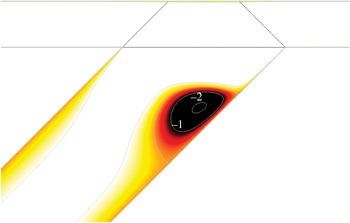
This quantity provides a measure of the extent to which recirculation is significant within the channel, and is illustrated in figure 4 for a demonstration case.
Dimensionless recirculation velocity,
 $\tilde{u} ^{\prime }$
, in the
 $x^{\prime }$
direction in the inlet channel scaled by the characteristic secondary channel velocity
 $U^{\prime }$
for a main channel height of
 $100~{\rm\mu}\text{m}$
, a secondary channel height of
 $250~{\rm\mu}\text{m}$
, and a Reynolds number of 20. All other parameters are as described in table 1. Significant recirculation is observed, with a maximum negative dimensionless velocity in excess of
 $-2$
.

The inlet Reynolds number
 $Re_{inlet}$
and the maximum dimensionless recirculation velocity
 $\tilde{u} ^{\prime }$
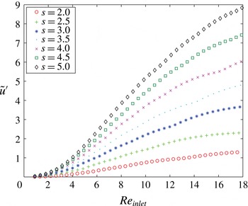
can then be tabulated over a wide range of conditions by varying the main channel Reynolds number and the secondary channel height. Figure 5 plots recirculation velocity as a function of inlet Reynolds number for a range of inlet heights and Reynolds numbers. This plot demonstrates that the value of
 $Re_{inlet}$
at which recirculation becomes important, such that
 $\tilde{u} ^{\prime }>1$
, is a strong function of the relative heights of the channels, defined as
 $s=h_{inlet}/h$
.


This result can be collapsed further by considering the relationship between the recirculation velocity
 $\tilde{u} ^{\prime }$
, the relative heights of the secondary and main channels,
 $s$
, the flow ratio
 $n$
, and the inlet channel angle
 ${\it\alpha}$
. As either
 $s$
or
 $n$
gets larger, the velocity in the primary channel becomes larger relative to that of the secondary channel. From (3.1), the relationship between the flow ratio, the channel velocity scales, and the channel heights can easily be expressed:
 $$\begin{eqnarray}\displaystyle \frac{U}{U^{\prime }}=ns. & & \displaystyle\end{eqnarray}$$
The fluid velocity in the main channel is the dominant source of fluid motion, and thus drives the recirculation. Since the recirculation effect is a result of the inertia in the primary channel, we expect that the dimensionless recirculation velocity
 $\tilde{u} ^{\prime }$
will increase as the primary channel velocity
 $U$
increases. From (3.4),
 $U\sim ns$
, so we expect a faster than linear increase in dimensionless recirculation velocity as the channel ratio
 $h$
or flow ratio
 $n$
is increased. It is therefore reasonable to consider the maximum recirculation velocity scaled to
 $(ns)^{2}$
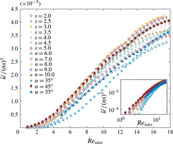
as a good measure of recirculation. This expectation is validated by figure 6, which illustrates that the recirculation behaviour from 585 numerical simulations conducted by varying channel ratio, flow ratio, inlet angle, and inlet Reynolds number all collapse onto a single curve.
Maximum dimensionless recirculation velocity
 $\tilde{u} ^{\prime }$
scaled by
 $(ns)^{2}$
, where
 $n$
is the volumetric flow ratio, and
 $s$
is the ratio of secondary to main channel height, as a function Reynolds number
 $Re_{inlet}$
as defined in (3.2). All simulation parameters are as listed in table 1 except as listed in the legend. The inset plots the same data on a log–log scale.

Although flow separation and recirculation play a key role in mixing, they are not the only source of non-idealities in the channel. It is customary to neglect edge effects for wide rectangular channels far from the walls, but those walls can play a very significant role when the flow bends at low or moderate Reynolds number, as observed in the case of Dean flow in a pipe or a rectangular channel (Dean Reference Dean1927; Di Carlo Reference Di Carlo2009). Even at low Reynolds number, the walls can induce significant secondary flows around sharp corners or bends with a non-constant radius of curvature (Shankar Reference Shankar2000; Lauga, Stroock & Stone Reference Lauga, Stroock and Stone2004; Guglielmini et al. Reference Guglielmini, Rusconi, Lecuyer and Stone2010). The recirculating eddies formed in such geometries have been shown to induce the formation of biofilm streamers when certain strains of bacteria are introduced (Rusconi et al. Reference Rusconi, Lecuyer, Guglielmini and Stone2010). Similar phenomena can be observed in contracting or expanding flows, which also have been shown to induce out-of-plane flow (Shankar Reference Shankar2000; Zhang et al. Reference Zhang, Li, Li and Alici2013).
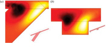
(a) Out-of-plane fluid flow velocity (surface) one quarter of the channel width away from the wall near the inlet of the three-dimensional channel with a height of
 $500~{\rm\mu}\text{m}$
and a Reynolds number of 10. A schematic of the cut plane is shown as an inset. As the fluid in the main channel bends downwards towards the secondary channel, the fluid is deflected towards the centre of the channel, represented by the blue region. Likewise, the upwards curvature of the fluid as it bends back into the main channel results in fluid being driven towards the wall represented by the red region. (b) A similar effect can be observed for a simple rectangular channel with a square pocket added. The average fluid velocity and curvature are similar, so the out-of-plane behaviour is also very similar.

In the case of the inlet geometry considered here, velocity gradients between the centreline of the channel and the wall drives flow out of plane, further enhancing mixing as shown in figure 7. Interestingly, the effective curvature of the fluid flow is not determined directly by the angle of the inlet, or the height of the channels, but by the deformation of the fluid flow as it curves upwards into the main channel. Figure 7(b) illustrates that the upwards curvature of the fluid, even in the absence of a secondary channel, contributes most strongly to the out-of-plane flow velocities. The net effect of the additional secondary flows is to enhance mixing further, with significant mass reaching the far wall of the channel even for channels as tall as
 $500~{\rm\mu}\text{m}$
, as shown in figure 2. This channel height corresponds to an effective inlet Reynolds number of
 $Re_{inlet}=14$
. As the channel height is decreased further, the effective inlet Reynolds number will increase, increasing the recirculation effects. This result suggests that this value represents an upper bound on the effective inlet Reynolds number in order to suppress recirculation.
4. Conclusion
This work captures the dominant design criteria describing the convergence of two colaminar liquid streams at moderate Reynolds number in rectangular channels. We find that for any operating condition, the recirculation velocity can be written as a function of the channel aspect ratio, the flow ratio, and the inlet Reynolds number,
 $\tilde{u} ^{\prime }/(ns)^{2}=F(Re_{inlet})$
. This insight can be used as a guide for future channel designs, and informs the intuition that the velocity gradient of the fluid as it passes from the secondary channel into the main channel drives recirculation. A complete understanding of the source of the recirculation behaviour is beyond the scope of this work, and remains a promising avenue of future research.
In addition to the recirculation effect, we have also identified and numerically observed wall-induced eddy currents that produce out-of-plane fluid flow that enhance mixing and disrupt the assumption of two-dimensional flow, even for relatively wide channels. These two effects conspire to establish a maximum effective inlet Reynolds number to maintain the validity of the fully developed unidirectional flow assumption. The inlet Reynolds number must be considered to ensure the species separation necessary for a wide range of applications, including systems incorporating chemical and electrochemical reactions.