Introduction
The wearable antenna, one of the major components fulfilling the requirements of modern technology, plays an essential role in making proper on/off the body communication possible [Reference Dayo, Cao, Wang, Rahman and Soothar1]. Simultaneously, many interesting antenna designs are being produced day by day that can be bent and laid on certain surfaces. Hence wearable antenna is expected to be more flexible without compromising the performance characteristics even though it undergoes deformations and near-human phenomena [Reference Mahmood, Ishak, Saeidi, Alsariera, Alani, Ismail and Soh2–Reference Hossain, Hassim, Azam, Islam and Hasan6]. Designing such an effective and compact wearable antenna is challenging due to the low-size antenna structure, which offers a small current path and impedance mismatch at lower frequencies. Keeping the main characteristics in mind, many investigators chose the microstrip patch antenna in combination with fractal technology to produce the desired characteristics such as flexibility [Reference Dar, Ahmed and Raees7], compact [Reference Naji8], multi-band, and broadband characteristics [Reference Mazen, Emran, Shalaby and Yahya9–Reference Ashraf, Jabbar, Arif, Riaz, Zubair and Mehmood14].
The wearable antenna mostly finds integrated applications in the human body, which is prone to deformations and stretching [Reference Muktadir, Nesar, Chakma, Biswas, Chowdhury and Hossain15, Reference Ali Khan, Raad, Tubbal, Theoharis, Liu and Foroughi16]. When the antenna undergoes bending or deformation, the antenna's performance is degraded due to the inhomogeneity in flexible substrate materials, height, and length distortions. The textile was susceptible to discontinuities and other factors. To allow deformation and flexibility, a typical compact-sized microstrip antenna design is one solution [Reference Boeykens, Vallozzi and Rogier17–Reference Mandal and Pattnaik19]. But there is a tradeoff between the deformation and compactness allowed for the wearable applications at WLAN standards. Also, thick flexible substrates or semi-flexible substrates susceptible to deformations can be utilized while designing the wearable antenna. The rigid/semi-flexible substrates are not the purpose choice in conformal applications. Therefore, a wearable antenna design involves choosing a shape to compromise the effective length/width during bending [Reference Seman, Ramadhan, Ishak, Yuwono, Abidin, Dahlan, Shah and Ashyap20].
However, the electromagnetic exposure limit in terms of specific absorption rate (SAR) shows a foremost part in designing the wearable antenna since the antennas are intended to operate near the human body. To mitigate these radiation problems, reflective/high impedance surfaces are inserted betwixt the antenna and the human body [Reference Yang, Yao, Yi, Huang, Wu and Xiao21]. This new surface causes a variation in the performance of the primary antenna. Designing such surfaces involves complex analysis and is time-consuming. However, inserting another layer in the name of HIS surface, the total integrated antenna thickness increases, leading to an increase in the antenna's volume.
In this work, a compact, robust and high gain antenna is developed by modifying a regular square shape. The attributes of the proposed antenna in respect of compactness, gain, and SAR limit are compared to the configurations published in the literature. The anticipated antenna is simulated for s-parameters and radiation patterns at the 2.45 GHz ISM band. A prototype is made to validate the proposed design and found a good impedance bandwidth of 5% and a high gain of 6.1 dBi. Also, the deformation analysis is performed by wrapping the antenna on foam cylinders of a specific radius. The particular shape of the radiator can withstand bending compared to the regular square shape. The SAR performance is also estimated and found to be within standards. The numerical simulations and experimental validation demonstrate that the anticipated antenna is extremely vigorous and novel to deformations and human tissue loading. The overall performance made the antenna suitable for wearable applications in WBAN. Besides this section, section “Antenna geometry and fabrication” refers to the evolution of the antenna geometry; section “Experimental result and discussion” refers to the results; section “SAR evaluation” refers to the SAR analysis followed by conclusions.
Antenna geometry and fabrication
Antenna design
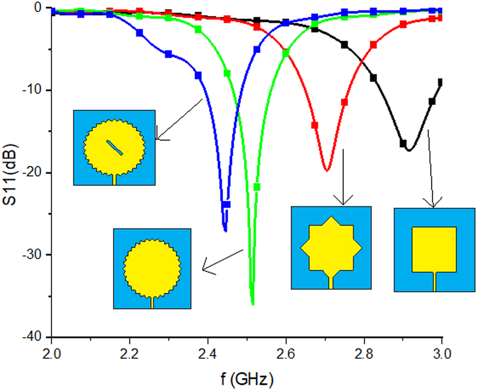
The wideband or multiband designs can be achieved with the use of fractal geometries. Nonetheless, fractal configurations are also designed to implement compact microstrip antennas. By adjusting the edge of the microstrip antenna, a boundary fractal structure can be accomplished. The proposed antenna structure is achieved by the successive spin and intersection of a similar length square patch shape, leading to an increased electrical length, thereby equivalent area of the patch. The idea is extended to include the properly cutting rectangular slot inside the saw-tooth boundary fractal patch antenna. The slots and notches on the patch enhance the current path length and decrease the resonant frequency further. Figure 1 exhibits the development process of the anticipated antenna. The antenna geometry is primarily derived from the regular square and circular-shaped patches. First, a square shape is chosen as the initial shape, and the dimensions are calculated using traditional methods [Reference Garg, Bhartia, Bahl and Ittipiboon22]. The motivation behind the design principle is to expand the current path length by making a fractal-like boundary that takes sharp edges and produces a compact antenna with better gain. As in the inset of Fig. 1, the initial square patch is rotated at an angle of 45° and overlaid on the initial shape to get iteration 1. The procedure is repeated for up to three iterations. Further, a rectangular slot of size 2 × 18 mm2, rotated with 45° angles, is inserted in the center of the saw-tooth boundary fractal antenna to achieve the required frequency of 2.45 GHz. A 50 Ω microstrip line is utilized to feed the antenna at the edge of the fractal boundary to achieve proper matching. All simulations are performed in the electromagnetic software CST MWS. Theoretically, the length of the initial patch is calculated using the traditional formula

S11 curves for various iterations of the proposed fractal boundary patch antenna.

where C 0 is the speed of light in free space, ɛreff is the effective permittivity.
This square patch is converted to a fractal boundary patch by sequential rotation and combination. The detail in the generated pattern can be expressed with the fractal dimension, and the dimension is estimated as

where N is the number of copies, θ is the initial scaling angle. The dimension of the fractal need not be an integer. The boundary can apply to those values of θ perfectly divisible by 360°. Parametric simulations are executed to optimize the dimensions of the proposed wearable antenna.
The initial length of the patch is determined as 38 mm, with a resonant frequency of 2.91 GHz. After three iterations, the frequency of resonance shifts to the desired 2.5 GHz. Additionally, the resonance frequency is shifted to 2.45 GHz by cutting a rectangular slot, as shown in Fig. 2. The etched rectangular slot in the radiator enhances the quality factor that contributes to good impedance matching, which reduces bandwidth, and a better impedance matching results in the desired resonance peak at 2.45 GHz. A parametric study is carried out in CST MW Studio to optimize the dimensions.
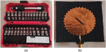
(a) Scalpel cutting tools set. (b) Front view of the fabricated antenna.

Fabrication procedure
The radiator scheme is refined over a low-cost jeans material, with a dielectric constant of 1.7 and a thickness of 0.02λ. Adhesive copper tape is utilized for the radiating patch on the top of the substrate and the full ground plane below the substrate. The extent of flexibility and simple adhesive copper layer allows for improving the degree of comfort level to the user. The fabrication process of a flexible antenna starts with the prototype using adhesive copper tape. The radiating patch on the front and full ground on the backside of the substrate are applied with copper tape. Flexible, low-cost jeans material of thickness 2.5 mm is used as a substrate material, making the antenna lightweight and conformal. The jeans layers are stacked one by one and stitched to get the required thickness, and then the copper tape is attached in accordance with the proposed shape.
It is challenging to attach a conducting copper tape of a different shape to a flexible fabric substrate. It may lead to errors and inaccuracy when dealing with sharp edges and complex shapes of a radiator. Scalpel cutting tools or stencil tools are utilized to maintain accurate and precise parts of antenna prototypes. Later, direct soldering connects the microstrip patch on top and the ground plane to the SMA connector. The cutting tool utilized for the fabrication and the prototype is shown in Figs 2(a) and 2(b).
Experimental result and discussion
Reflection coefficient under flat condition
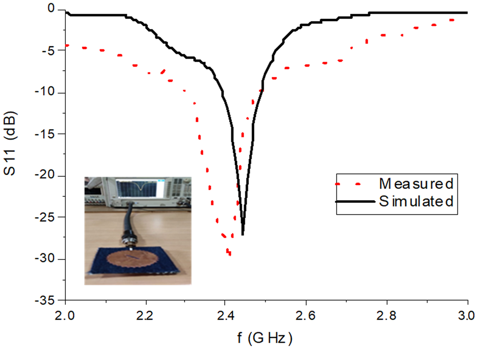
The parameters are measured with the help of an Agilent N5247A Network analyzer. Figure 3 depicts the measurement setup and reflection coefficient curve for simulated and measured under the flat condition in free space. It is realized that the simulated reflection coefficient shows −26.10 dB at 2.45 GHz, whereas the measured shows −30.75 dB at 2.43 GHz with slightly increased bandwidth. The simulated and measured bandwidths are 4.2 and 5%, individually. The slight discrepancy between the measured and simulated is due to prototyping tolerances and losses associated with the flexible substrate.
Reflection coefficient of the anticipated antenna.

Reflection coefficient under deformation
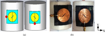
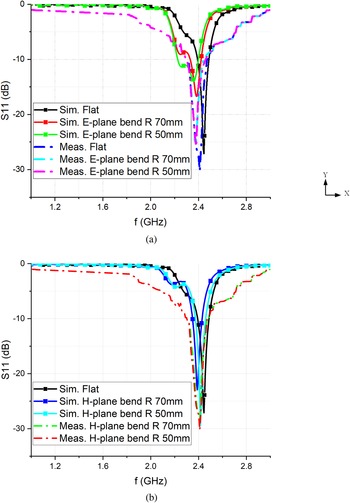
The major prerequisite of WBAN applications is that the antenna proposed should be operable under deformation, such as bending and crumpling, when functioning near or around the human body or any other rough surface. To authenticate the bending, the anticipated antenna is bent in E-plane and H-plane directions with the radii of curvature of 70 and 50 mm, respectively. For measurements, 3D fixtures of foam are built to provide selected curvature, as shown in Fig. 4. A minor, almost insignificant frequency shift is observed when bent in the E-plane direction, whereas in the H-plane direction, a small change in the bandwidth is observed. It is very consistent compared to the simulation reflection coefficient. From Fig. 5, the reflection coefficient slightly increases when the antenna is bent, maintaining almost the same resonant frequency as the antenna on a flat surface. This proves that the bending effect on the saw-tooth-shaped boundary patch antenna is almost negligible. It is the consequence of the antenna being bent in the length/width direction, the change in the effective length/width of the proposed shape is almost equal to the original length/width. Therefore, the proposed shape can hold the original dimensions during bending. Under deformation conditions, the measured reflection coefficient almost gives the same results as simulated results. Hence this type of antenna can be very flexible to utilize in wearable WBAN applications.
Proposed antenna bends on foam cylinders along E and H-planes: (a) simulated, (b) practical.

Effect of bending on the proposed antenna under various bending scenarios: (a) E-plane bending, (b) H-plane bending.

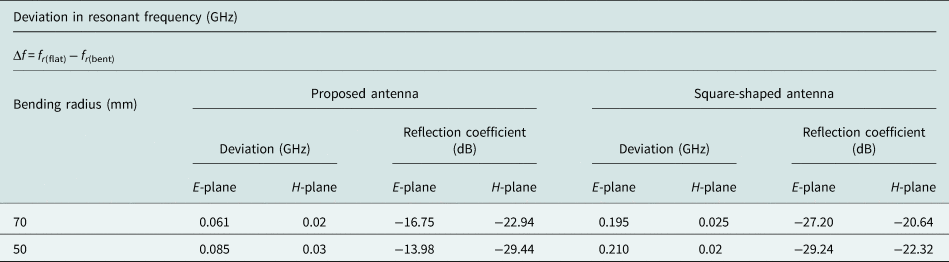
A comparative study is also done to verify the critical bending for different shapes, namely the proposed and initial square patch. The deviation in frequency shift for both the proposed and square-shaped antenna is calculated and tabulated in Table 1.
Assessment of bending behavior of the anticipated antenna with the regular square shape of the radiator

It is observed from Table 1 that E-plane bending has a considerable effect on square-shaped antennas, whereas it is almost negligible on the saw-tooth-shaped antenna. However, the H-plane bending shows a negotiable effect on both antennas. This proves that the proposed shape performs well even in a deformation environment, satisfying the requirement of wearable applications in WBAN.
Radiation characteristics
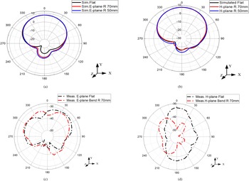
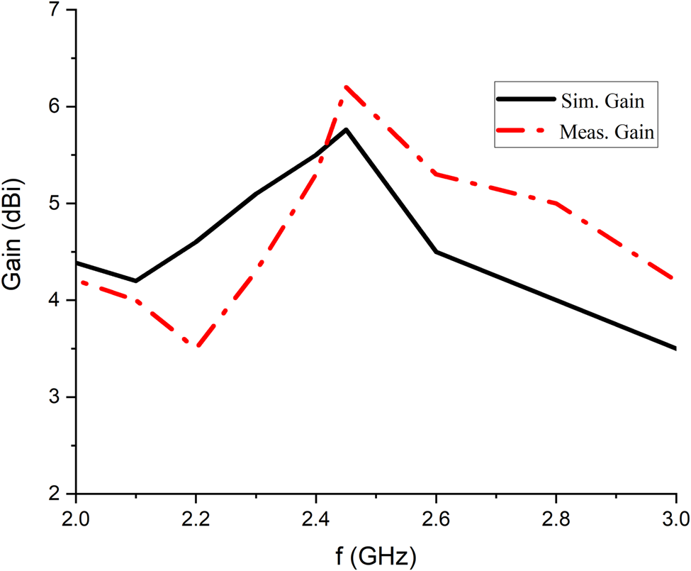
Generally, wearable antennas are intended to have forward radiation or directive patterns instead of omnidirectional patterns. This is considered to keep the health standards of humans due to the unwanted radiation into the human body. Regularly, the radiation pattern is described in two principal planes, namely E-plane and H-plane. In this paper, the antenna is placed in the X–Y plane facing +Z-direction, so the Y–Z plane, i.e. Ø = 90° in the E-plane and X–Z plane, represents the H-plane where Ø = 0°. All investigations on radiation patterns are done in the same manner throughout the paper. The simulated E and H-plane patterns under flat and bent scenarios are shown in Figs 6(a) and 6(b). At 2.45 GHz, the antenna shows a forward gain of 5.76 dBi under flat conditions, whereas a slightly different gain is observed under the bend scenario. The gain reduction is due to the appearance of discontinuity of the antenna upon deformation. Although E and H-plane patterns seem alike, small back radiation is observed. It is concluded that the radiation pattern is also affected when the antenna undergoes deformation. Yet, the safety of this antenna is still verified, and the SAR level estimated is in the following sections.
Simulated radiation patterns (dB) along (a) E-plane and (b) H-plane. Measured radiation patterns (dBm) along (c) E-plane and (d) H-plane.

The prototype antenna has a directed radiation pattern having a forward gain of 6.12 dBi at 2.45 GHz. A slight change in the back radiation is detected when the antenna is bent in a particular direction. Figures 6(c) and 6(d) show the measured far-field radiation pattern. Confirming the simulation predictions, the measurement shows nearly close values. The proposed antenna shows a slightly high gain when the antenna is under deformation significantly either in E-plane or H-plane. This is due to the increased current densities at the discontinuity formed when deformation or bending [Reference Zhou, Fang and Jia18]. The back lobes in the measured patterns account for the measurement setup limitations.
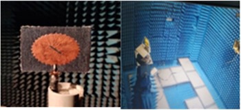
Figure 7 depicts the measurement setup inside the anechoic chamber for radiation pattern. The far-field radiation patterns under flat and bending scenarios are measured at the middle frequency of 2.45 GHz. Due to the consistency of the simulated radiation patterns, a single measurement is taken into consideration for measurement under a bent scenario. The antenna is placed on an automatic rotating platform in an anechoic chamber. The pattern is observed at three discrete frequencies. The patterns are measured in dBm in both E and H-planes to observe accurate antenna gain variations.
Measurement setup inside the anechoic chamber for radiation pattern.

Overall the anticipated antenna demonstrates advantageous performance considering the deformations. Figure 8 shows the comparison of simulated and measured gain values.
Simulated and measured peak gain of the anticipated antenna.

Antenna performance on human tissue loading
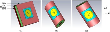
Practically, it is necessary to make sure the performance of the wearable antenna on the body. Numerical simulations are conducted by CST MW studio. The proposed antenna is situated on the four-layer phantom model, developed to impersonate the chest and arm of the human body as in Fig. 9. The chest and arm are impersonated by a cuboid of 150 × 150 × 40 mm3, a cylinder with a diameter of 80 mm and length of 150 mm, respectively. The antenna reflection coefficient and radiation characteristics are evaluated and compared with free space antenna performance for both simulated and measured.
Positioning of the proposed antenna on (a) chest, (b) arm along Y-axis, (c) arm along X-axis.

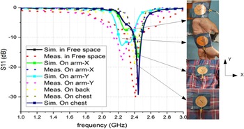
Mounting the fabricated antenna prototype onto the human body as a body-worn system leads to altering the antenna's performance due to the high dielectric nature of the human body. The prototype antenna is measured on the chest, arm, and back of a male volunteer of height 161 cm and weight of 75 kg. The anticipated antenna is positioned on the chest, back, and bent on the arm to evaluate its performance, as demonstrated in Fig. 10. This investigation provides extra reliability to the proposed work by instigating the real human volunteer instead of simulation models.
S11 curves of the proposed antenna when located on the chest and arm.

As described in Fig. 10, the proposed antenna S11 is slightly shifted from 2.45 GHz to lower frequencies when situated on the chest and back of the human body. This is because of the effectiveness of the ground plane and the availability of large areas on the human chest and back. When the proposed antenna was bent on the arm along the X and Y-axis, S11 shifted to even lower frequencies due to the impedance mismatch caused by both bending and the presence of the high dielectric nature of the human body. Except for the small variations, the simulated and measured S11 curves agree. It demonstrates that the full ground plane isolates the antenna and the human body.
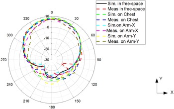
Figure 11 demonstrates the radiation characteristics of the proposed antenna when placed on the chest and arm. The results illustrate that the radiation characteristics are comparable with the free space and the human body. It can also uphold its pattern shape as in free space with negligible differences that don't disturb the radiation performance. The realized gain of the anticipated antenna loaded with human tissue is increased slightly with respect to free space as a result of reflection from the human body, and the radiation efficiency decreased due to lossy tissue.
Radiation patterns of the proposed antenna when placed on the human body.

SAR evaluation
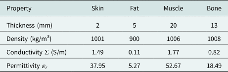
There are many difficulties allied with the wearable antenna operating near the human body, particularly the change of characteristic performance of the antenna due to the absorption of electromagnetic energy. This context was enumerated by measuring the electromagnetic exposure limit. However, the proposed antenna has a full ground plane that will isolate and resist radiation penetration into the human body. This will tend to reduce the SAR levels. To estimate SAR, the anticipated antenna was positioned on a four-layered phantom of overall size 150 × 150 × 40 mm3. The phantom model comprises four layers, namely skin (thickness 2 mm), fat (thickness 5 mm), muscle (thickness 20 mm), and bone (thickness 13 mm). The characteristics of each of the layers are listed in Table 2.
Properties of the human phantom model [Reference Ashyap, Abidin, Dahlan, Majid, Shah, Kamarudin and Alomainy23]

The simulated maximum SAR values for 1 and 10 g of average tissue for the input power of 100 mW are listed in Table 3.
Simulated SAR value

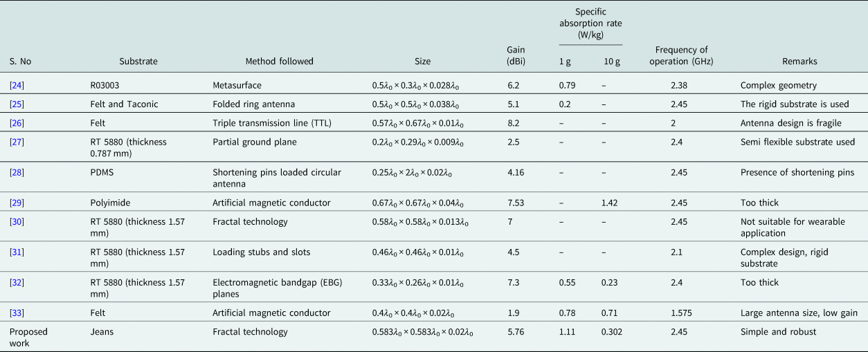
According to the standards by FCC, the value of SAR must be smaller than 2 W/kg for 10 g of tissue and 1.6 W/kg for 1 g of tissue. It is witnessed from Table 3 that the evaluated SAR is at an acceptable level and obeys both standards. A comparison of the anticipated work with the most recent methods is presented in Table 4. Observing Table 4, the proposed antenna is significantly different from the previously reported designs because it enables a more compact footprint with superior performance in terms of gain and SAR. Therefore, it is determined that the anticipated antenna is a potential candidate for wearable applications in WBAN.
Comparison of the proposed antenna with the state art designs

Where λ 0 is the free space wavelength, – is not applicable.
Conclusion
A new flexible and high gain wearable antenna based on the saw-tooth-shaped fractal boundary for WLAN applications is productively designed, and measurements are carried out. The proposed antenna provides an impedance bandwidth of 4.2% and a peak gain of 5.76 dBi at the 2.45 GHz ISM band. The antenna shows a negligible effect on the resonant frequency upon bending compared with a regular square-shaped patch antenna. Also, the estimated SAR values were found to be within the prescribed limits by FCC. Hence, the proposed saw-tooth boundary fractal antenna is a commendable candidate for wearable WLAN applications.
Conflict of interest
None.
 Sandhya Mallavarapu is currently pursuing her Ph.D. in Electronics and Communications Engineering at the National Institute of Technology Warangal. She received her M.Tech. degree in Communications and Signal Processing from RVR & JC, Guntur, Andhra Pradesh, India in 2013 and B.Tech. degree in Electronics and Communications Engineering from Vignan's Engineering College, Guntur, Andhra Pradesh, India in 2010. Her research interests include flexible and wearable multi-band antennas. She has two international conference papers and two papers in various journals indexed in SCI/ESCI to her credit.
 Anjaneyulu Lokam was born in 1967 in India. He received his B.Tech. (ECE) in 1989, M.Tech. in 1991, and Ph.D. in 2010 from N.I.T, Warangal, and Telangana, India. He worked as a project officer at the Institute of Armament Technology, Pune, India, for 5 years from 1991 and was involved in the Design of Surface Borne and Air Borne Radar Systems for Clutter Measurement Applications. Later, he worked as a Staff Scientist at Helios Systems, Madras, India, for 2 years and developed radio wave propagation assessment software modules for ship-borne radars. He has been with the Department of Electronics and communications engineering at the National Institute of Technology, Warangal, India, since 1997. His area of interest includes computer networks, electromagnetic field theory, microwave, and radar engineering, microwave remote sensing, and neural networks and fuzzy logic systems. He has completed few defense-related R&D projects and has 100 papers to his credit in national and international conferences and journals. He is a Life member of ISTE and a member of IEEE, IEEE Antennas and Propagation Society, IEEE Signal Processing Society.