Nomenclature

1. Introduction
Continuum robots (CRs) excel in navigating confined, cluttered environments, making them indispensable in minimally invasive surgeries, industrial operations, and space exploration [Reference Rus and Tolley1–Reference Tsegay, Pathak, Samantaray and Merzouki4]. Unlike rigid-link robots, CRs adapt to constraints, enabling operations in restricted spaces like turbine and aeroengine inspections [Reference Xin Dong, David Palmer, Raffles, Rabani and Kell5–Reference Rao, Salzman and Burgner-Kahrs8]. CRs are classified by actuation systems, including tendon-driven [Reference Janabi-Sharifi, Jalali and Walker9], concentric tube [Reference Zhang, Sven Lilge and Burgner-Kahrs10], magnetically actuated [Reference Yang, Yang, Cao, Cui and Zhang11], and shape memory alloy-based robots [Reference Yang, Geng, Walker, Branson, Liu, Dai and Kang12].
TDCRs offer distinct advantages over other types. Their compact, lightweight design and precise, high-DOF control make them ideal for space-constrained applications like surgeries [Reference Walker13, Reference Webster and Jones14]. Unlike pneumatic and hydraulic systems, TDCRs rely on energy-efficient mechanical actuation [Reference Rucker and Webster III15], and their scalability supports microscale surgical robots and larger industrial tools [Reference Hannan and Walker16]. Tendon actuation minimises backlash, ensuring smooth, accurate motion for tasks such as surgical suturing [Reference Simaan, Taylor and Flint17], while their simple, cost-effective construction using cables and pulleys enhances accessibility [Reference Mahvash and Dupont18]. Additionally, TDCRs operate silently, an important advantage in hospital and research settings [Reference Jones and Walker19]. Advancing TDCR kinematics, dynamics, and control, which enable flexible backbone bending through tendon actuation, is critical for applications requiring precision and manoeuvrability in restricted environments. Recent research has focused on advanced dynamic modelling and control strategies for tendon-driven continuum robots. Piecewise constant curvature (PCC) and Euler–Lagrange-based robust controllers such as inverse dynamic PID, fuzzy logic, and sliding mode control have been developed to ensure reliable trajectory tracking under varying loads and disturbances [Reference Ba, Dong, Mohammad, Wang, Axinte and Norton20, Reference Aner, Awad and Shehata21]. Adaptive schemes employing function approximation have further enhanced robustness by compensating for model uncertainties and external perturbations [Reference Xu and He22]. More recently, data-driven and learning-based methods – including model-based nonlinear controllers [Reference Zhang, Du, Zhang, Wu, Zheng, Li and Song23], LSTM-based force estimation [Reference Xiang, Zhang, Sun, Qiu, Fang, Mi, Wang, Xiong and Lu24], and reinforcement learning approaches such as fuzzy RL and deep deterministic policy gradients [Reference Goharimanesh, Mehrkish and Janabi-Sharifi25, Reference Kargin and Kołota26] – have demonstrated superior precision and stability compared to traditional PCC-based designs. Complementary sensing and feedback innovations – combining dual displacement sensors with on-board visual tracking [Reference Fang, Dong, Mohammad and Axinte27] and model-free adaptive Kalman filters [Reference Li, Kang, Branson and Dai28] – have further improved tip-tracking accuracy and path consistency while streamlining sensor requirements.
Despite the progress in control and sensing, modelling tendon-driven continuum robots remains challenging due to their infinite degrees of freedom and non-linear material behaviour [Reference Mishra, Samantaray and Chakraborty29]. To address these challenges, several frameworks have been proposed: the PCC and its variant variable PCC, finite element models [Reference Firdaus, Paranjape and Vadali30], and Cosserat-rod formulations [Reference Chawla, Frazelle and Walker31–Reference Till, Aloi and Rucker33]. While finite element and Cosserat-rod approaches provide high fidelity, their computational demands limit real-time use [Reference Sciavicco and Siciliano34]. In contrast, PCC-based kinematic models strike a practical balance, offering sufficient accuracy and the speed required for quasi-static control [Reference Walker13].
Beyond tip trajectory control, there is a growing need for shape and section trajectory control, especially in multi-section TDCRs deployed in unstructured environments. Each section requires at least three actuating tendons to achieve motion in 3D space, as tendons can only actuate under tension [Reference Webster and Jones14]. Figure 1 shows a schematic of a two-section TDCR with three actuating tendons for each section. Under the PCC assumption, one component of the tip coordinates depends on the other two [Reference Webster and Jones14], allowing the length of any two tendons to uniquely define the tip coordinate, with a constrained equation defining the length of the third tendon. If the number of tendons per section increased in a multi-section TDCR, it would increase the number of constrained equations, leading to modelling and control complexities in existing approaches.
Schematic of two-section tendon-driven TDCR. (a) Routing of physical (
 $a_1$
,
 $b_1$
, &
 $c_1$
) for section I and (
 $a_2$
,
 $b_2$
, &
 $c_2$
) for section II and distribution of tendons along the disk. (b) Conceptual representation of a virtual tendon (in a black dashed line) that lies in the bending plane (sky blue plane).

This paper exploits these observations and introduces the concept of virtual actuation space to address such limitations. A generalised tendon mapping matrix, applicable to TDCRs with any number of sections and any number of actuating tendons per section, relates the virtual actuation space to the tendon lengths, enabling fully decoupled control of each section and simplifying multi-tendon, multi-section designs beyond the three-tendon PCC constraints of prior methods.
A generalised forward and inverse kinematics framework for multi-section TDCRs in virtual actuation space is formulated in this paper, maintaining scalability across varying robot configurations. It considers two inputs in virtual actuation space per section to uniquely define the configuration of the section. The generalised tendon mapping matrix captures the constrained and coupling effects of the tendons and their lengths, regardless of the total number of tendons or sections. Subsequently, control formulation in virtual actuation space for multi-section TDCRs is proposed, emphasising both section and trajectory control. The approach utilises a virtual actuation space to decouple the control of individual sections. The controller can effectively manage the complex relationship between task and tendon space, enabling control of TDCRs in confined spaces. The control methodology is validated experimentally on a multi-section TDCR, demonstrating its effectiveness in achieving accurate and reliable tip position control. The results indicate that the proposed approach can significantly improve the performance of TDCRs in confined and cluttered environments, paving the way for their broader adoption in medical and industrial applications.
The primary contributions of this study, which extend beyond established PCC-based methods by enabling scalable, decoupled shape and trajectory control for arbitrary multi-tendon/multi-section TDCRs, are as follows:
-
1. A generalised virtual actuation space kinematics framework for tendon-driven continuum robot sections of any configuration, using two inputs per section to define 3D poses, overcoming the three-tendon constraints and modelling complexities of prior PCC approaches.
-
2. A generalised tendon mapping matrix from the virtual actuation space to the actual tendon space, enabling decoupled control of individual sections to follow any trajectory in their workspace (including shape control alongside tip trajectory adherence) and resolving inter-section couplings absent in existing methods.
-
3. A control formulation in the virtual actuation space for point-to-point and trajectory tracking tasks, incorporating task-space constraints to manage tendon complexities in confined environments.
-
4. Theoretical proofs of control convergence alongside experimental validation on a two-section TDCR, confirming accurate tip position control and enhanced reliability in cluttered settings.
The rest of the paper is organised as follows: an overview of multi-section TDCR and foundational assumptions for theoretical formulation is provided in Section 2. A brief description of virtual actuation space formulations is given in Section 3. Subsequently, generalised forward kinematics is presented in Section 4. Section 5 presents the concept of decoupling TDCRS and the generalised tendon mapping matrix. Section 6 describes the state estimation. The control architecture is provided in Section 7. The details of the experimental setup are given in Section 8. Hardware implementation, point-to-point tracking, trajectory tracking with section control and the detailed discussion are presented in Section 9. Section 10 provides final remarks and future work.
2. Multi-section TDCR
TDCRs, like the example shown in Figure 1, have a flexible backbone that allows continuous bending along their length and can be configured as a single-section or multi-section. In a multi-section design, each section has a flexible backbone, three actuating tendons, and evenly spaced disks. Each disk has a central hole for the backbone attachments and peripheral holes for tendons, with at least three tendons around each disk. The tendons, labelled
 $a_i$
,
 $b_i$
, and
 $c_i$
for the
 $i^{th}$
section, are attached to motor pulleys to adjust the length for bending. The other end of each tendon attaches to the intermediate disk between sections. Figure 1 shows a two-section TDCR. For Section I, the tendons end at the disk between Sections I and II, which serves as the free end of Section I and the base for Section II. The other tendons end at the free end of the two-section TDCR, as shown in Figure 1(a). Tendons in the same section are separated by
 $\frac {2 \pi }{3}$
radians, with
 $\gamma _i$
representing the angle of tendon
 $a_i$
relative to the
 $Y_i$
axis of the section base disk. The backbone’s elasticity allows it to return to its original shape when tendons are relaxed, and varying tendon lengths create different bending shapes. The theoretical model for the behaviour of tendon-driven continuum robots (TDCRs) is derived based on the following assumptions:
-
1. Constant curvature approximation: The pulling of tendons causes the TDCR to bend into a concave shape. Therefore, the kinematic model is based on the piecewise constant curvature framework [Reference Webster and Jones14].
-
2. Backbone properties: The backbone, which primarily determines the behaviour of the TDCR, is made of a single type of material and is considered isotropic and homogeneous.
-
3. Tendon characteristics: The tendons are assumed to be inextensible and frictionless. Given that the tendon diameter is on the order of
 $10^{-3}$
of the backbone diameter, the tendons are considered massless.
-
4. Equal initial lengths: The tendons are assumed to have equal initial lengths to prevent buckling.

While these assumptions simplify the theoretical framework, they do not fully capture the real-world behaviour of TDCRs. Therefore, a closed-loop control methodology is employed to manage and control the actual behaviour of the system accurately.
3. Conceptualising virtual actuation space
To understand the generalisation of virtual actuation space, we will first focus on one section of a multi-section TDCR. For articulation in a 3D workspace, each section needs at least three actuating tendons. Despite the complexity of 3D articulation, each section can be simplified to planar articulation within a specific bending plane, the plane in which a section bends. Figure 1(b) shows the representation of virtual tendons for a single section instead of three tendons to achieve the same results. For multiple sections of TDCR, a single tendon within each section’s bending plane achieves this. Thus, any 3D articulation can be represented as a combination of planar movements of all sections, each controlled by a single virtual tendon, as shown by the dashed line in Figure 2. Changes in the lengths of physical tendons, or joint space, correlate directly with changes in virtual tendons, defining the virtual actuation space. The tendon space is given by,
 \begin{equation} \mathbf{l}=\begin{bmatrix} l_{a_1} & l_{b_1} & l_{c_1} & l_{a_2} & l_{b_2} & l_{c_2} & \cdots \end{bmatrix}^T_{3n \times 1} \end{equation}
where
 $\{l_{a_i}, l_{b_i}, l_{c_i}\} \in \mathbb{R}$
. The virtual actuation space is given by,
 \begin{align} \mathbf{l_v}&=\begin{bmatrix} l_{v_1} & l_{v_2} & l_{v_3} & \cdots & l_{v_n} \end{bmatrix}^T_{n \times 1}\\[-10pt]\nonumber \end{align}
 \begin{align} \boldsymbol{\alpha }&=\begin{bmatrix} \alpha _1 & \alpha _2 & \alpha _3 & \cdots & \alpha _n \end{bmatrix}^T_{n \times 1}\\[-10pt]\nonumber \end{align}
 \begin{align} \mathbf{v}&=\begin{bmatrix} \mathbf{l_v} & \boldsymbol{\alpha } \end{bmatrix}^T_{2n \times 1} \end{align}
Multi-section TDCR with a yellow base and free disks. (a) Each section is shown with its three actuating tendons and bending planes. (b) Virtual tendons on the concave side of each section in the respective bending plane.

where
 $l_{v_i} \in \mathbb{R} \setminus \{0\}$
and
 $\alpha _i \in \mathbb{R}$
, with
 $l_{v_i}$
representing the length of the virtual tendons and
 $\alpha _i$
representing the angle of the bending plane of the sections. The angle made by the bending plane with the
 $Y_i$
axis of the base frame of the
 $i^{th}$
section is called the bending plane angle
 $\alpha _i$
. Let
 $L_i$
represent the backbone length of the
 $i^{th}$
section, and let
 $r_d$
denote the radius of each of the
 $k$
disks per section. Each section has a frame attached to the base disk, with the base frame
 $\{OXYZ\}_{i}$
and
 $\{OXYZ\}_{i+1}$
attached to the free end of the
 $i^{th}$
section, which is the base frame for
 $i+1^{th}$
, as shown in Figure 2. In this frame, the
 $X$
axis is normal to the base disk surface, while the
 $Y$
and
 $Z$
axes follow the right-hand coordinate convention. The base disk of section I is grounded. The free end disk of the
 $i^{th}$
section serves as the base disk for the
 $i+1^{th}$
section, except for the last section, where
 $i=1,2, \cdots , n$
. Each section can bend in a different bending plane. The bending of all sections influences the position of the tip of the TDCR in the task space, which is the free end of the
 $n^{th}$
section. The unbent state of all sections is defined as the natural state of the TDCR.
4. Generalised forward kinematics in virtual actuation space
In the virtual actuation space of the
 $i^{th}$
section, denoted by
 $l_{v_i}$
and
 $\alpha _i$
, these parameters represent the change in length of the virtual tendon and the angle of the bending plane between the
 $i+1^{th}$
and
 $i^{th}$
frames, as illustrated in Figure 2(b). Assuming constant curvature for each section, the relationship between the virtual actuation space, the TDCR bending angle, and the radius of curvature of the section is given by,
 \begin{align} L_i - l_{v_i} &= \theta _i (R_{ci} - r_d) \nonumber\\ L_i &= \theta _i R_{ci} \end{align}
where
 $R_{ci}$
and
 $\theta _i$
are the radius of curvature and the bending angle, respectively. The relationship is further expressed as,
 \begin{equation} \frac {L_i}{R_{ci}} = \frac {L_i - l_{v_i}}{R_{ci} - r_d}; \, R_{ci} = \frac {L_i r_d}{l_{v_i}};\, \theta _i = \frac {L_i}{R_{ci}} = \frac {l_{v_i}}{r_d} \end{equation}
The tip coordinates of the
 $i^{th}$
section in the local frame are given by
 \begin{equation} \begin{bmatrix} x_i \\[3pt] y_i \\[3pt] z_i \\[3pt] \end{bmatrix} = \begin{bmatrix} R_{ci} \sin \theta _i \\[3pt] (R_{ci} - R_{ci} \cos \theta _i) \cos \alpha _i \\[3pt] (R_{ci} - R_{ci} \cos \theta _i) \sin \alpha _i \end{bmatrix} \end{equation}
where
 $[x_i \ y_i \ z_i]^T$
are the generalised coordinates of the
 $i^{th}$
section in its body frame.
4.1. Coordinates transformation
The coordinates of each section can be transformed into the global frame using a homogeneous transformation matrix. The rotation matrix can be calculated using the Rodrigues rotation formula [Reference Murray, Sastry and Zexiang35]. The angle of rotation is the bending angle of the section
 $\theta _i$
, and the axis of rotation is the normal vector of the bending plane. The normal vector of the
 $i^{th}$
section,
 $\boldsymbol{\omega }$
, is given by,
 \begin{equation} \boldsymbol{\omega }= \frac {\mathbf{{o_i o_{i+1}}} \times \mathbf{x_i}}{\|\mathbf{{o_i o_{i+1}}} \times \mathbf{x_i}\|} \end{equation}
The rotation matrix of the
 $i^{th}$
frame relative to the
 $(i-1)^{th}$
frame is given by,
 \begin{equation} \mathbf{R}^{i}_{i-1}=e^{\boldsymbol{\hat {\omega }_i}{\theta _i}} = \mathbf{I} + \boldsymbol{\hat {\omega }} \sin \theta _i + \boldsymbol{\hat {\omega }}^2 (1 - \cos \theta _i) \end{equation}
where
 $\mathbf{I}$
is the identity matrix of order three,
 $\mathbf{R}^{i}_{i-1}$
is an element of rotation group
 $\mathbb{SO}(3)\in \mathbb{R}^3$
and
 $\boldsymbol{\hat {\omega }}$
is an element of Lie algebra
 $ \mathfrak{so}(3)$
which is a skew-symmetric matrix. The homogeneous transformation obtained by the translation and rotation from the
 $(i-1)^{th}$
frame to the
 $i^{th}$
frame is defined as
 $\mathbf{H}^{i}_{i-1}$
, given by,
 \begin{equation} \mathbf{H}^{i}_{i-1} = \begin{bmatrix} \mathbf{R}^{i}_{i-1} & \mathbf{O}^{i}_{i-1} \\[4pt] 0 & 1 \end{bmatrix} \end{equation}
where
 $\mathbf{O}^{i}_{i-1}$
is the translation vector of the
 $i^{th}$
frame from the
 $(i-1)^{th}$
frame.
 \begin{equation} \boldsymbol{\zeta _i} = \mathbf{H}^{2}_{1} \mathbf{H}^{3}_{2} \dots \mathbf{H}^{i}_{i-1} \begin{bmatrix} x_i & y_i & z_i \end{bmatrix}^T \end{equation}
where
 $\boldsymbol{\zeta _i}$
are the generalised coordinates of the tip of the
 $i^{th}$
section in the global frame
 $\{O X Y Z\}_1$
, which are functions of
 $l_{v_i}$
and
 $\alpha _i$
. Thus, the generalised coordinates of an
 $n$
-section TDCR are given by,
 \begin{equation} \boldsymbol{\zeta } = \begin{bmatrix} \boldsymbol{\zeta _1} & \boldsymbol{\zeta _2} & \boldsymbol{\zeta _3} & \cdots & \boldsymbol{\zeta _n} \end{bmatrix}^T_{3n \times 1} \end{equation}
where
 $\boldsymbol{\zeta } \in \mathbb{R}^{3n}$
represents the generalised coordinates of the TDCR section’s free ends, which are functions of
 $\mathbf{v}$
.
5. Section decoupling
Each section of a TDCR inherently possesses only two independent coordinates of its free end in the local body frame, even though three tendons are required to uniquely define its configuration through a constraint equation. As the number of tendons per section increases, the number of such constraint equations also increases, resulting in greater mathematical complexity in modelling the kinematics, Jacobian, and control laws.
To address this, the Virtual Actuation Space (VAS) framework simplifies the system by reducing it to a two-input, two-output structure per section, effectively decoupling the multiple sections of a TDCR. The tendon constraints and coupling effects arising from routing are handled through a tendon mapping matrix. Consequently, decoupling the TDCR into individual
 $ n$
-section units simplifies the overall control and analysis.
5.1. Utilising virtual actuation space inverse kinematics
Consider a
 $n$
section TDCR with frame
 $\{OXYZ\}_1$
as the fixed frame shown in Figure 2(a). Inverse kinematics involves determining
 $l_{v_i}$
and
 $\alpha _i$
from the given generalised coordinates of each section in global frame
 $\boldsymbol{\zeta _i}$
, depicted in Figure 2(a), which describe the free end of each section in a global frame. The generalised coordinates are transferred into the local frame for each section. By transforming the problem into local coordinates, each section can be treated as an independent entity, thereby providing a straightforward approach to identifying the elements of the virtual actuation space.
The transformation of generalised coordinates into the local frame propagates from frame
 $1$
to frame
 $n$
. The transferred local coordinates
 $[x_i,y_i,z_i]^T$
using the homogeneous transformation matrix are given by,
 \begin{equation} [x_i\quad y_i\quad z_i]^T=\mathbf{H}^{0}_{i-1}(\boldsymbol{\zeta }_i-\boldsymbol{\zeta }_{i-1}) \end{equation}
To compute
 $\mathbf{H}^{0}_{i-1}$
, the bending angle
 $\theta _i$
and the offset
 $\mathbf{O}^{i}_{i-1}$
are utilised for each section and can be obtained through straightforward trigonometric relations [Reference Firdaus and Vadali36]. Since the coordinate of each section’s free end is already established in its local frame using Eq. (13), the virtual joint space parameters
 $l_{v_i}$
and
 $\alpha _i$
for the
 $i^{th}$
section are determined.
5.2. Elements of virtual actuation space
For local frame coordinates from Eq. (13) can be used to determine
 $l_{v_i}$
and
 $\alpha _i= atan2\left (\frac {z_i}{y_i}\right )$
for the
 $i^{th}$
section of an
 $n$
-section TDRC. Each TDRC section is divided into
 $m$
modules, with each module spanning between two consecutive disks, as shown in Figure 3(b). The length of the
 $j^{th}$
module is
 $L_{m_i}^j$
, where
 $j$
ranges from
 $1$
to
 $m$
. Each module contains part of the flexible backbone and a virtual tendon represented as the dashed line in Figure 3, and the disk thickness is assumed to be zero. Because the disks are equidistant, the bending angle of each module
 $\overline {\theta }_i$
, is obtained by dividing
 $\theta _i$
by
 $m$
. This angle also represents the rotation of the top disk of the module relative to the bottom disk about an axis perpendicular to the plane of bending and passing through the centre of the bottom disk, as shown in Figure 3(c). The vectors
 $\mathbf{o}_{i}^{j-1}\mathbf{o}_{i}^{j}$
(connecting centres of consecutive disks) and
 $\mathbf{o}_{i}^{j}\mathbf{p}_{i}^{j}$
(connecting the disk centre to the virtual tendon interaction point) are given by [Reference Firdaus and Vadali36],
 \begin{align} \mathbf{o}_{i}^{j-1} \mathbf{o}_{i}^{j}&= \frac {L_i}{\theta _i}\left[ \sin \overline {\theta }_i \, \cos \alpha _i(1-\cos \overline {\theta }_i) \, \sin \alpha _i(1-\cos \overline {\theta }_i)\right]^T\nonumber\\ \mathbf{o}_{i}^{j} \mathbf{p}_{i}^{j}&=\left[0, \,r_d \cos \alpha _i, \,r_d \sin \alpha _i\right]^T \end{align}
Using Eq. (14), the vector
 $\mathbf{p}_{i}^{j-1}\mathbf{p}_{i}^{j}$
, which represents the vector of the virtual tendon in the bent state of the module, is given by,
 \begin{equation} \mathbf{p}_{i}^{j-1} \mathbf{p}_{i}^{j}=\mathbf{o}_{i}^{j-1} \mathbf{o}_{i}^{j}+[\mathbf{R}]^{j}_{j-1} \mathbf{o}_{i}^{j} \mathbf{p}_{i}^{j}-\mathbf{o}_{i}^{j-1} \mathbf{p}_{i}^{j-1} \end{equation}
where the
 $\big [\mathbf{R}\big ]^{j}_{j-1}$
rotation matrix is found out by using Rodrigues rotation formula [Reference Murray, Sastry and Zexiang35] with angle
 $\overline {\theta }_i$
and axis perpendicular to the plane of bending. The required length of the virtual tendon of the module is given by,
 \begin{align} l_{v_i}^j&= \|\mathbf{p}_{i}^{j} \mathbf{p}_{i}^{j+1}\|-L_{m_i}^j\nonumber\\ l_{v_i}&=\sum _{j=1} ^{m} l_{v_i}^j \end{align}
where
 $l_{v_i}^j$
is the virtual tendon length of a module and
 $l_{v_i}$
is of a section. Now that the
 $l_{v_i}$
and
 $\alpha _i$
are known, the individual sections of the multi-section TDRC can be controlled individually. However, a virtual tendon is not a physical tendon; therefore, a mapping is required that can relate the virtual tendons to the actual TDCR tendons.
(a) Virtual tendon of
 $i^{th}$
section of the muti-sections TDCR. (b) Details of a module with a module bending angle. (c) Angle made by the disks of the single module.

5.3. Generalised tendon mapping matrix
We will first focus on a single module and a section to understand the tendon mapping matrix. Then, the idea can be generalised for all sections of the TDCR. The bending angle of a module is equivalent to the angle made by two consecutive disks. It can be further understood as the rotation of one disk about the axis perpendicular to the bending plane passing through the disk’s centre, as depicted in Figure 4. When the disk rotates, the interaction point of actual tendons
 $a_i$
,
 $b_i$
, and
 $c_i$
with the disks will move on the circle of radius
 $r_{a_i}$
,
 $r_{b_i}$
, and
 $r_{c_i}$
around the axis of rotation. Thus, the arch
 $l_{a_i}^j$
,
 $l_{b_i}^j$
, and
 $l_{c_i}^j$
are the required changes in actuation space for a module of a section of TDCR.
 $\gamma _i$
is the smallest angle of the line joining the disk’s centre and the actual tendon’s interaction point with one of the axes (Y-axis) of the body fixed frame.
 $\gamma _i$
is a constant that describes the distribution of the tendons around the disks as shown in Figure 4. The arch
 $l_{a_i}^j$
,
 $l_{b_i}^j$
, and
 $l_{c_i}^j$
are given by,
 \begin{align} l_{a_i}^j&=r_{a_i} \overline {\theta }_i=\cos\!(\alpha _i-\gamma _i) r_d \overline {\theta }_i=\cos\!(\alpha _i-\gamma _i) l_{v_i}^j \nonumber\\[5pt] l_{b_i}^j&=r_{b_i} \overline {\theta }_i=\cos\!\left(\frac {2\pi }{3}-\alpha _i+\gamma _i\right) r_d \overline {\theta }_i=\cos\!\left(\frac {2\pi }{3}-\alpha _i+\gamma _i\right) l_{v_i}^j\nonumber\\[5pt]l_{c_i}^j&=r_{c_i} \overline {\theta }_i=\cos\!\left(\frac {4\pi }{3}-\alpha _i+\gamma _i\right) r_d \overline {\theta }_i=\cos\!\left(\frac {4\pi }{3}-\alpha _i+\gamma _i\right)l_{v_i}^j \end{align}
From (16) and (17), a mapping matrix can be formulated for a single section with three actuating tendons as follows:
 \begin{equation} \begin{bmatrix} l_{a_i} & l_{b_i} & l_{c_i} \end{bmatrix}^T =\begin{bmatrix} \cos\!\left(\alpha _i - \gamma _i\right)\\[5pt] \cos\!\left(\dfrac {2\pi }{3} -\alpha _i+\gamma _i\right)\\[12pt] \cos\!\left(\dfrac {4\pi }{3} -\alpha _i+\gamma _i\right) \end{bmatrix} l_{v_i} \end{equation}
The mapping matrix in Eq. (18) has three elements for three actual tendons of the same section. If there is an increase in the number of tendons per section, say
 $4$
, the tendon mapping matrix is given by,
 \begin{equation} \begin{bmatrix} l_{a_i} & l_{b_i} & l_{c_i} & l_{d_i} \end{bmatrix}^T =\begin{bmatrix} \cos\!(\alpha _i - \gamma _i)\\[5pt] \cos\!\left(\dfrac {2\pi }{4} -\alpha _i+\gamma _i\right)\\[12pt] \cos\!\left(\dfrac {4\pi }{4} -\alpha _i+\gamma _i\right)\\[12pt] \cos\!\left(\dfrac {6\pi }{4} -\alpha _i+\gamma _i\right) \end{bmatrix} l_{v_i} \end{equation}
The tendon mapping matrix for a single section, regardless of the number of tendons, can be formulated by calculating elements in the virtual space. Consider a two-section TDCR, where each section is actuated by three tendons, as shown in Figure 1. Section I is actuated by six tendons, while Section II is actuated by three tendons. When Section I bends, all six tendons must be actuated. In contrast, bending Section II requires actuating only its three respective tendons. Consequently, the tendon mapping matrix for Section I consists of six elements, whereas the mapping matrix for Section II comprises three elements. The mapping of two sections and the actuating length of actual tendons is given by,
 \begin{equation} \begin{bmatrix} l_{a_1} \\[5pt] l_{b_1} \\[5pt] l_{c_1} \\[5pt] l_{a_2} \\[5pt] l_{b_2} \\[5pt] l_{c_2} \end{bmatrix} =\begin{bmatrix} \cos\!\left(\alpha _1 - \gamma _1\right) \\[5pt] \cos\!\left(\dfrac {2\pi }{3} -\alpha _1+\gamma _1\right) \\[12pt]\cos\!\left(\dfrac {4\pi }{3} -\alpha _1+\gamma _1\right)\\[8pt] \cos\!\left(\alpha _1 - \gamma _1-\gamma _2\right) \\[7pt] \cos\!\left(\dfrac {2\pi }{3} -\alpha _1+\gamma _1+\gamma _2\right) \\[12pt] \cos\!\left(\dfrac {4\pi }{3} -\alpha _1+\gamma _1+\gamma _2\right) \end{bmatrix} l_{v_1} + \begin{bmatrix} 0 \\[5pt] 0 \\[5pt] 0\\[5pt] \cos\!\left(\alpha _2 - \gamma _1-\gamma _2\right) \\[8pt] \cos\!\left(\dfrac {2\pi }{3} -\alpha _2+\gamma _1+\gamma _2\right) \\[12pt] \cos\!\left(\dfrac {4\pi }{3} -\alpha _2+\gamma _1+\gamma _2\right) \end{bmatrix} l_{v_2} \end{equation}
Similarly, the virtual joint space is mapped into the actual joint space for multi-section TDCR using the generalised mapping matrix given by,
 \begin{equation} \mathbf{l}=\mathbf{T}\mathbf{l_v} \end{equation}
where,
 $\mathbf{T}$
is a
 $3n \times n$
matrix and given by,
 \begin{equation} \mathbf{T}=\begin{bmatrix} \mathbf{T}_1 & \mathbf{T}_2 & \cdots & \mathbf{T}_{i}\\[5pt] \mathbf{O}_1 & \mathbf{O}_2 & \cdots &\mathbf{O}_i \end{bmatrix}^T;\ i=1,2,\cdots n \end{equation}
where,
 $\mathbf{O}_i$
is a
 $3 \times n-i$
zero matrix and
 $\mathbf{T}_{i}$
is a
 $3 \times i$
matrix, given by,
 \begin{equation} \mathbf{T}_{i}=\begin{bmatrix} \cos\!\left(\alpha _1 -\sum _{j=1}^{j=i}\gamma _j\right) & \cdots & \cdots & \cos\!\Big(\alpha _i -\sum _{j=1}^{j=i}\gamma _j\Big)\\[8pt] \cos\!\left(\dfrac {2\pi }{3} -\alpha _1 +\sum _{j=1}^{j=i}\gamma _j\right) & \cdots & \cdots & \cos\!\left(\dfrac {2\pi }{3} -\alpha _i +\sum _{j=1}^{j=i}\gamma _j\right) \\[11pt] \cos\!\left(\dfrac {4\pi }{3} -\alpha _1 + \sum _{j=1}^{j=i}\gamma _j\right) & \cdots & \cdots & \cos\!\left(\dfrac {4\pi }{3} -\alpha _i+\sum _{j=1}^{j=i}\gamma _j\right) \end{bmatrix} \end{equation}
The tendon mapping matrix is utilised to determine the actual tendon lengths of each section from the length of the virtual tendons. The actual tendon lengths are converted to TDCR’s motor pulley angles to control the TDCR’s tip position.
Depiction of actuation space formalisation on a module basis from virtual space. The green dashed line lies in the bending plane.

6. State estimation in virtual actuation space
Differentiating Eq. (12), the relation of task space velocity and acceleration with virtual actuation space velocity and acceleration is given by,
 \begin{eqnarray} \dot {\boldsymbol{\zeta}}&=& {\mathbf{J}_{\boldsymbol{v}}} {\mathbf{v}}\nonumber\\ \ddot {\boldsymbol{\zeta}}&=& {\mathbf{J}_{\boldsymbol{v}}} \mathbf{v} + \mathbf{H}_{\mathbf{v}} \mathbf{v} \end{eqnarray}
where,
 $\boldsymbol{\mathbf{J}_{\boldsymbol{v}}}$
and
 ${\mathbf{H}_{\boldsymbol{v}}}$
are
 $\in \mathbb{R}^{3n \times 2n}$
called the Jacobian matrix and the Hessian matrix, respectively.
 $\boldsymbol{\mathbf{J}_{\boldsymbol{v}}}$
mapped the virtual actuation space’s first derivative to that of the task space and mapped the virtual actuation space’s second derivative to that of the task space. Using Euler’s discretisation method, Eq. (24) is reformulated as,
 \begin{align} \mathbf{v}(t+\Delta t)&=\mathbf{v}(t)+(\boldsymbol{\mathbf{J}_v^\dagger } \dot {\boldsymbol{\zeta }}) \Delta t \nonumber\\ \dot {\mathbf{v}}(t+\Delta t)&=\dot {\mathbf{v}}(t)+(\boldsymbol{\mathbf{J}_v^\dagger } \ddot {\boldsymbol{\zeta }}-\boldsymbol{{\mathbf{H}_{\boldsymbol{v}}}}\dot {\mathbf{v}}(t))\Delta t \end{align}
In Eq. (25),
 $\mathbf{v}(t)$
and
 $\dot {\mathbf{v}}(t)$
are the current state of virtual actuation space, and
 $\mathbf{v}(t+\Delta t)$
and
 $\dot {\mathbf{v}}(t+\Delta t)$
are the updated state of virtual actuation space,
 $t \in \mathbb{R}$
is the current time, and
 $\Delta t$
is the time step.
 $\dagger$
signifies the Moore-Penrose pseudoinverse.
7. Control methodology
Virtual actuation space control methodology utilises the task space error to provide control input in the virtual actuation space. The mapping matrix maps the control input into the actual joint space. The control input is provided to the actuators to control the tendon length. The task space error is defined as the difference between the desired generalised coordinate and the current generalised coordinates of TDCR. The error is given by,
 \begin{equation} \mathbf{e}=\boldsymbol{\zeta }_d-\boldsymbol{\zeta } \end{equation}
where,
 $\boldsymbol{\zeta }_d \in \mathbb{R}^{3n}$
is desired generalised coordinates and
 $\boldsymbol{\zeta } \in \mathbb{R}^{3n}$
is generalised current coordinates. The control law for acceleration and velocity tracking is given by,
 \begin{align} \ddot {\mathbf{v}}&=\boldsymbol{\mathbf{J}_{\boldsymbol{v}}}^\dagger \big(\ddot{\boldsymbol{\zeta }}_d- {{\mathbf{H}_{\boldsymbol{v}}}}\dot{\mathbf{v}} + \mathbf{K}_d \ \mathbf{e} + \mathbf{K}_p \mathbf{e} \big )\nonumber\\ \dot {\mathbf{v}}&=\boldsymbol{\mathbf{J}_{\boldsymbol{v}}}^\dagger \big (\dot {\boldsymbol{\zeta }}_d+\mathbf{K}_p \mathbf{e}\big ) \end{align}
where,
 $\mathbf{K}_d \in \mathbb{R}^{3n \times 3n}$
and
 $\mathbf{K}_p \in \mathbb{R}^{3n \times 3n}$
are derivative and proportional positive definite diagonal gain matrices.
7.1. Convergence
Multiplying Eq. (27) by
 $\boldsymbol{\mathbf{J}_{\boldsymbol{v}}}$
both sides and with little rearrangement, we have,
 \begin{align} {\mathbf{J}_{\boldsymbol{v}}}\ \mathbf{v}+{{\mathbf{H}_{\boldsymbol{v}}}}\mathbf{v} & =\ddot {\boldsymbol{\zeta }}_d + \mathbf{K}_d \ \mathbf{{e}} + \mathbf{K}_p \ \mathbf{e}\nonumber\\ {\mathbf{J}_{\boldsymbol{v}}} \dot {\mathbf{v}}&= \dot {\boldsymbol{\zeta }}_d +\mathbf{K}_p \mathbf{e} \end{align}
from Eqs. (24 and (28) we have,
 \begin{align} \ddot {\mathbf{\boldsymbol{\zeta }}}-\ddot {\mathbf{\boldsymbol{\zeta }}}_d&=\mathbf{K}_d \dot {\mathbf{e}}+ \mathbf{K}_p \mathbf{e}\nonumber\\ \dot {\mathbf{\boldsymbol{\zeta }}}-\dot {\mathbf{\boldsymbol{\zeta }}}_d&= \mathbf{K}_p \mathbf{e} \end{align}
 \begin{equation} \begin{split} \ddot {\mathbf{e}}+ \mathbf{K}_d \dot {\mathbf{e}}+\mathbf{K}_p \mathbf{e} =0\\ \dot {\mathbf{e}}+\mathbf{K}_p \mathbf{e} =0 \end{split} \end{equation}
If
 $\mathbf{K}_p$
and
 $\mathbf{K}_d$
are positive definite matrices, then Eq. (30), error converges to zero when time tends to infinity [Reference Jadav and Palanthandalam-Madapusi37]. The control block diagram is shown in Figure 5 to explain the control architecture of the TDCR. The control algorithm is implemented in Python and LabView.
Overview of the proposed virtual actuation space-based control block diagram.

8. The experimental setup
The experimental setup used to validate the proposed methodology is shown in Figure 6. It consists of a two-section tendon-driven continuum manipulator using a feedback loop with a motion capture sensor to track the desired trajectory. The setup includes a 370 mm long, 16 mm diameter polyurethane rod as the backbone, divided into two equal sections. Six 0.7 mm steel strand tendons pass through 3D-printed PLA disks, with three tendons actuating each section. For Section I,
 $\gamma _1$
is 0, and for Section II,
 $\gamma _2$
is
 $\pi /3$
radians. Six DC servo motors, three for each section, precisely control tendon lengths for accurate TDCR bending using an optical encoder and real-time controller (SbRio 9,629).
Experimental setup of two sections of TDCR.

LED markers provide tip coordinates using a high-resolution motion capture (MoCap) camera (PhaseSpace Impulse X2), with eight cameras mounted around the setup that operate at 960 Hz. Each section tip has three markers forming an equilateral triangle, with the centroid providing generalised coordinates. PLA disks keep tendons parallel to the backbone and guide them to an 18 mm radius motor pulley. Guiding pulleys direct tendons to the motor pulley, with the setup mounted on aluminium extrusions.
The real-time controller operates in a closed-loop system, managing motor movements based on a LabView-based script and encoder feedback. The motor rotates to the desired angle at a speed specified by the host computer via USB. The current tip position of the TDCR is captured by a motion capture (MoCap) system, which sends the data to the host computer using a Python script.
The host computer executes the control algorithm, computing the necessary motor inputs based on the error between the desired and current coordinates provided by the MoCap system. These control inputs, defined in virtual space, are converted into tendon lengths. Dividing the tendon lengths by the pulley radius
 $r_p$
yields the motor angles
 $\mathbf{\Omega }$
, which are used by the real-time controller and motor driver to achieve the desired configuration.
9. Results and discussion
9.1. Trajectory tracking simulation
The simulation results for trajectory tracking are presented in Figures 7–9. For the two-section TDCR, Figure 7(a) demonstrates accurate tracking of the desired circular trajectory, while Figure 7(b–g) illustrates the evolution of generalised coordinates for both sections. The three-section TDCR simulation, shown in Figure 8(a), successfully tracks the desired trajectory, with each section coordinating to achieve precise tip positioning. The corresponding generalised coordinates for all three sections are presented in Figure 8(b–j). Similarly, Figure 9(a) depicts trajectory tracking of a varying curvature path using a four-section continuum robot, with the generalised coordinate evolution for each section shown in Figure 9(b–m). These simulation results validate the scalability and effectiveness of the proposed virtual actuation space formulation and control framework across different robot configurations.
(a) Tracking of circular trajectory by two-section TDCR, (b–d) tracking of generalised coordinates of Section I, and (e–g) tracking of generalised coordinates of Section II.

(a) Tracking of spiral trajectory by three-section TDCR, (b–d) tracking of generalised coordinates of Section I, (e–g) tracking of generalised coordinates of Section II, and (h-j) tracking of generalised coordinates of Section III.

(a) Tracking of changing curvature trajectory by four-section TDCR, (b–d) tracking of generalised coordinates of Section I, (e–g) tracking of generalised coordinates of Section II, (h–j) tracking of generalised coordinates of Section III, and (k–m) tracking of generalised coordinates of Section IV.

9.2. Point-to-point tracking
In the workspace of the TDCR, five sets of points forming a pentagon are tracked using a virtual space-based control methodology. The goal is for the TDCR tip to reach each of these points sequentially. Figure 10 shows the tracking of these points by the TDCR tip. The desired points are depicted in Figure 10(a). Changes in the generalised coordinates of the TDCR tip denoted
 $\zeta _2(1)$
,
 $\zeta _2(2)$
, and
 $\zeta _2(3)$
, over time, are shown in Figures 10(b), 10(c), and 10(d), respectively. The tracking error for each coordinate is displayed in red plots on the corresponding plots, with the error axis labelled on the right side of each plot. The TDCR starts from its initial state, reaches the first point in 25 s, and remains there for 50 s. It then moves to the subsequent points, taking 10 s to reach each one. The root mean squared errors (RMSE) for
 $\zeta _2(1)$
,
 $\zeta _2(2)$
, and
 $\zeta _2(3)$
are 3.4 mm, 3 mm, and 1.6 mm, respectively, and their relative errors with respect to the length of TDCR are 0.9
 $\%$
, 0.8
 $\%$
, and 0.4
 $\%$
. Because the pentagon’s vertices lie in a plane parallel to the
 $\zeta _2(2)$
–
 $\zeta _2(3)$
plane, the desired
 $\zeta _2(1)$
remains constant. As shown in Figure 10(b), there are five peaks because the TDCR briefly leaves the pentagon plane when tracking these points.
(a) Pentagon set points, (b), (c), and (d) generalised coordinates of the tip, with position errors. The dynamics of the error ( ) are labelled on the blue y-axis on the right side.

9.3. Trajectory tracking with section control
Several feasible trajectories are generated for both sections using generalised forward kinematics, collectively referred to as Tr
 $1-5$
. These include a twopetalled flower shape and a spiral trajectory shown in Figure 11, a circular trajectory shown in Figure 12, a curve in a different plane shown in Figure 13, and a curve in the same plane with different orientations shown in Figure 14. The generalised coordinates at the tip of section i are shown in each figure’s subplots (a–c), while those of section ii are in subplots (d–f). The 3D trajectories are depicted in subplots (g). The tracking error of each generalised coordinate is shown in the red-coloured plot at the bottom of the respective plots with the blue-coloured axes.
(a), (b), and (c) show the generalised coordinates and tip tracking errors for section i, while (d), (e), and (f) depict the same for section ii. The error dynamics () are plotted with the right y-axis in blue colour, just beneath each plot, corresponding to their respective trajectories. (g) Illustrates both the required trajectories and the actual tracking trajectories.

The description of the plot is the same as Figure 11. Trajectory tracking with independent section control, (h) and (i) show a camera view of TDCR with different frames from top to bottom.

The description of the plot is the same as Figure 11. (g) Trajectory in different planes, (h) shows a camera view of TDCR with frames from top to bottom.

The description of the plot is the same as Figure 11. (g) Trajectory in different orientations, (h) shows a camera view of TDCR with frames from top to bottom.

In Tr 1 and Tr 2, both sections’ tips follow similar paths, effectively behaving as a single-section TDCR, as shown in Figure 11. Tr 3 highlights trajectory tracking with section-shape control: during the first half of the motion, section i bends while section ii remains unbent, and during the second half, section ii bends to track the circular path, leaving section i fixed as shown in Figure 12(a–f). Minor deviations in
 $\zeta _1(1)$
,
 $\zeta _1(2)$
, and
 $\zeta _1(3)$
occur due to the compliant nature of the TDCR, but the controller works to minimise or bind these errors. The camera view of the TDCR is shown in Figure 12(h) for the first half of the motion, and Figure 12(i) for the second half, displayed frame by frame from top to bottom. The red box indicates camera 1, and the blue box indicates camera 2. In Figure 12(h), it can be observed that only section i bends during the first half, lying in the plane passing through camera 1, while camera 2 also captures it bending in a single plane. For the second half of the motion, Figure 12(i) shows that the tip of section i remains almost fixed (intersecting the white dashed line in all frames), while the tip of section ii tracks the circular trajectory.
In Tr 4, TDCR follows trajectories in different planes, resulting in a twisted “S” shape bending, as shown in Figure 13(h). In Tr 5, TDCR follows trajectories in the same planes but with different orientations, creating a twisted “
 $\mathbf{?}$
” shape bending, as illustrated in Figure 14(h). Figure 13(g) illustrates that the tip of section I bends in the
 $\zeta (1)-\zeta (2)$
plane, which is orthogonal to camera 1 and parallel to camera 2. The white dashed line in Figure 13(h) represents the intersection line of the orthogonal planes of both cameras. From Figure 13(h), it is clear that the tip of section i stays on this dashed line in camera 1, while the tip of section ii moves away. Figure 14(g) shows a trajectory in the same plane but with a different orientation. Since the plane of Tr 5 is orthogonal to camera 1 and parallel to camera 2, the TDCR remains aligned with the dashed line in camera 1 throughout the tracking, as the tip of section i moves away and the tip of section ii coincides with the dashed line of camera 2, as shown in Figure 14(h).
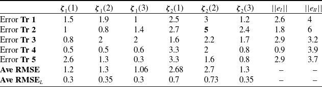
The RMSE for each trajectory is presented in Table I. Each row of Table I provides the tracking error of the generalised coordinates of the TDCR, followed by the RMSE and RMSE
 $_L$
(RMSE normalised by the length of the TDCR). The last two columns list the average error norm for generalised tip coordinates of each section, denoted as
 $\|e_I\|$
for section I and
 $\|e_{II}\|$
for section II.
 $\| e_i \|$
is less than 3 mm and
 $\|e_{II}\|$
is 4 mm, which shows that the TDCR can follow the trajectory nicely.
RMSE of tracking for different trajectories in mm.

TDCR has tracked all given trajectories Tr (1–5) within the acceptable bounds of error. The maximum RSME is
 $5$
mm amongst all generalised coordinates for all the trajectories, as shown in Table I. The tracking error of generalised coordinates for both sections tracks all trajectories. Tr (1–5) Error plots for each generalised coordinate exhibit spikes when the MoCap marker leaves the field of view or is disturbed by varying environmental lighting conditions. During these instances, the system receives no feedback, leading to brief tracking lapses. However, once the markers re-enter the field of view, the system resumes tracking with bounded errors, rapidly correcting itself as feedback is restored.
9.4. Comparison with existing methods
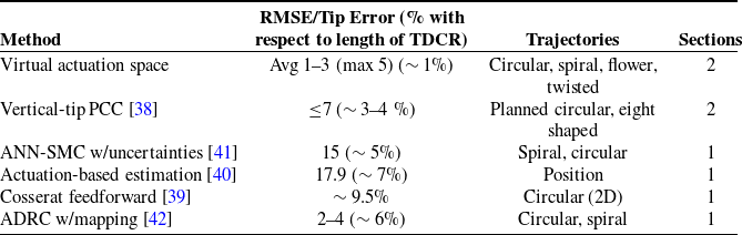
To contextualise the performance of our virtual actuation space-based controller, we compare it against recent state-of-the-art approaches for trajectory tracking for TDCRs, focusing on positional accuracy (e.g., RMSE or tip error) for similar tasks like circular and spiral paths. Table II summarises key metrics from representative works, alongside ours. Our method achieves the lowest average RMSE (1.2–2.7 mm across coordinates, max 5 mm) and relative errors (0.3–0.73% of TDCR length), outperforming Lai et al. [Reference Lai, Huang, Lu, Zhao and Chu38] (RMSE
 $\leq$
7 mm for vertical-tip circular tracking in a two-segment soft robot) and Pekris et al. [Reference Pekris, Williams, Atkins, Georgilas and Bailey39] (accuracy within 9.5% relative error for 2D circular paths using Cosserat-based feedforward control). For dynamic shape estimation during tracking, Feliu-Talegon et al. [Reference Feliu-Talegon, Mathew, Alkayas, Adamu and Renda40] report higher average tip errors (1.79 cm or 17.9 mm) relying solely on actuation readings, without explicit decoupling for multi-sections. Chen et al. [Reference Chen, Ming and Qin41] demonstrate robust tracking under uncertainties (e.g., fluid viscosity) via ANN-FNITSMC but require computationally intensive neural approximation; our model-based decoupling yields bounded errors post-FOV loss with simpler, scalable kinematics for arbitrary sections/tendons. Similarly, Cao et al. [Reference Cao, Yang, Wang, He, Liu and Xie42] improve ADRC-based tracking for circular/spiral paths (RMSE 2–4 mm in simulations), yet struggle with multi-section coupling; our approach extends this to independent section trajectories (e.g., Tr 3–5) with sub-4 mm section-specific errors (
 $\Vert e_I \Vert \leq 2.9$
mm,
 $\Vert e_{II} \Vert \leq 4$
mm), enabling shape control alongside tip adherence in cluttered spaces. Overall, the proposed framework advances beyond these by providing fully decoupled, hardware-agnostic control with enhanced accuracy and scalability, validated on a two-section TDCR.
Comparison of trajectory tracking accuracy (RMSE/Tip error in mm) across methods.

9.5. Discussion
The experimental results validate the efficacy of the proposed virtual actuation space framework for kinematic modelling and control of multi-section TDCRs. By reformulating the actuation problem into a decoupled, theoretically two-input-two-output system per section, the VAS enables precise trajectory tracking while allowing independent shape control of each section. Simulations of two-, three-, and four-section TDCRs demonstrate excellent scalability, with accurate replication of the prescribed trajectories across generalised coordinates as illustrated in Figures 7, 8, and 9. Hardware experiments yielded compelling performance metrics: point-to-point tracking of pentagonal vertices achieved RMSE values of 1.6–3.4 mm (0.4–0.9% of TDCR length), while trajectory tracking (Tr 1–5) produced an average RMSE of 1–3 mm per coordinate as presented in Table I, with normalised errors below 1% of the 370 mm backbone length. In point-to-point tracking,
 $\zeta _2(1)$
represents the coordinate along the robot’s length, while
 $\zeta _2(2)$
and
 $\zeta _2(3)$
represent the planar coordinates at a given
 $\zeta _2(1)$
height. Although steady-state errors in
 $\zeta _2(2)$
and
 $\zeta _2(3)$
are effectively zero, a small steady-state error of approximately 2 mm persists in
 $\zeta _2(1)$
due to actuator resolution limitations. These outcomes confirm millimetre-level precision relative to the robot’s scale, underscoring the framework’s practical effectiveness in quasi-static operations.
The enhanced performance stems primarily from section decoupling via the generalised tendon mapping matrix
 $\mathbf{T}$
and the VAS representation itself. Traditional multi-section TDCR control grapples with coupled tendon interactions, where actuation of one section inadvertently influences others due to shared tendon routings (e.g., the six tendons for Section I in a two-section design, as in Figure 1. This coupling amplifies modelling errors and control complexity [Reference Webster and Jones14, Reference Rao, Quentin Peyron and Burgner-Kahrs43, Reference Raimondi, Russo, Dong and Axinte44]. In contrast, the VAS collapses the three-tendon actuation per section into a single virtual tendon length
 $l_{v_i}$
within the bending plane, defined by
 $\alpha _i$
, while
 $\mathbf{T}$
explicitly maps these virtual inputs to physical tendon lengths
 $\mathbf{l}$
Eqs. (18–20). This mapping, structured as a block-diagonal matrix with submatrices
 $\mathbf{T}_i$
and zero blocks
 $\mathbf{O}_i$
, isolates section-specific contributions, preventing propagation of actuation errors across sections. For instance, in Tr 3 Figure 12, Section I bends independently in the first half-trajectory with Section II unactuated (
 $\mathbf{T}_2$
effectively zeroed), yielding bounded deviations in
 $\zeta _1$
(<2 mm) despite compliance-induced perturbations. The decoupling reduces the effective dimensionality from
 $3n$
(tendon space) to
 $2n$
(VAS), simplifying Jacobian
 $\mathbf{J}_v$
Eq. (24), which enhances real-time solvability and minimises numerical ill-conditioning.
Furthermore, the VAS inherently leverages the PCC assumption more effectively than direct tendon-space methods. By parameterising motion in the bending plane Figure 1(b), the framework enforces uniqueness via the virtual tendon arc length
 $l_{v_i} = r_d \theta _i$
Eqs. (7–16), eliminating the need to resolve geometric constraints among the three physical tendons. This structural consistency translates to lower tracking errors, as evidenced by the module-wise discretisation Figure 3, which captures discrete disk rotations more accurately than continuum approximations alone. The control law Eq. (27), operating in VAS with task-space feedforward and PD gains, exploits this by inverting
 $\mathbf{J}_v^\dagger$
to directly compensate for nonlinearities, achieving exponential error convergence Eq. (30) without aggressive tuning that could excite unmodelled dynamics.
Regarding potential singularities, the VAS framework encounters degeneracy when
 $l_{v_i} = 0$
, corresponding to the unbent (straight) configuration of a section. From Eq. (6), the radius of curvature is
 $R_{c_i} = L_i r_d / l_{v_i}$
; as
 $l_{v_i} \to 0$
,
 $R_{c_i} \to \infty$
, making
 $\mathbf{J}_v$
singular due to vanishing bending angle
 $\theta _i = l_{v_i} / r_d \to 0$
. This kinematic singularity implies a loss of instantaneous controllability in the bending plane, potentially leading to degraded accuracy or control failure near straight postures, akin to workspace boundaries in rigid manipulators. To mitigate this, the domain of
 $l_{v_i}$
is restricted to
 $\mathbb{R} \setminus \{0\}$
, and in practice, if
 $l_{v_i}$
approaches zero (e.g., due to numerical drift or near-straight desired poses), it is regularised by replacing it with a small positive
 $\epsilon$
(e.g.,
 $10^{-5}$
times the section length).
In the experimental validation, feedback from the motion capture system is acquired at 960 Hz but downsampled to 100 Hz to accommodate the quasi-static motion assumption of the kinematic model and avoid inertial effects. At this sampling rate and under quasi-static conditions, the experimental tracking exhibits no observable latency, confirming real-time control performance. The kinematic-based controller imposes minimal computational burden, enabling real-time implementation at the selected sampling rates, while the quasi-static assumption remains appropriate for the demonstrated manipulation tasks and ensures model validity throughout the experiments.
Overall, the VAS framework advances TDCR control by bridging kinematic simplicity with decoupled execution, enabling shape-aware tracking essential for cluttered environments like minimally invasive surgery or duct inspection. Its generalisability to
 $n\gt 2$
sections (simulations) and variable tendon counts Eq. (20) positions it for hybrid actuation paradigms, fostering broader adoption in precision robotics.
10. Conclusions
This study presents a generalised virtual actuation space framework for forward and inverse kinematics of TDCRs, alongside a control strategy that leverages this space with task-space feedforward velocity or acceleration terms to enable precise trajectory tracking. Theoretical analysis confirms the convergence of task-space errors.
A primary innovation lies in the decoupling of individual sections, reducing each to a theoretically two-input, two-output system, while the tendon mapping matrix accommodates arbitrary tendon counts per section and inter-tendon couplings. This facilitates independent trajectory following for each section, supporting diverse robot shapes within the workspace. Experimental validation on a two-section TDCR demonstrates effective tracking across varied paths (e.g., circular, spiral, floral, and twisted), with average root-mean-square errors (RMSE) of 1–3 mm across generalised coordinates and length-normalised RMSE
 $_L$
below 1% of TDCR length. These errors can be further minimised through higher-precision actuators and encoders.
As detailed in Table II, our method yields superior positional accuracy compared to recent benchmarks in multi-section scenarios. This scalability extends to TDCRs with additional sections, unlocking potential in medical robotics (e.g., minimally invasive procedures), industrial automation, and confined-space inspection tasks. Future work may explore integration with real-time sensing for enhanced adaptability in dynamic environments.
Acknowledgements
The authors thank the Gujarat Council on Science and Technology for financial support. The authors specifically thank Prof Harish J. Palanthandalam-Madapusi for his discussions and support and the committee members. Special thanks to Smit Prajapthi for helping in developing the experimental setup. They also acknowledge feedback from the IITGN Robotics Lab team and thank IIT Gandhinagar for their ongoing support.
Author contributions
Md Modassir Firdaus: conceptualisation, formal analysis, investigation, methodology, software, validation, visualisation, writing – original draft. Shail Jadav: conceptualisation, formal analysis, software. Madhu Vadali: conceptualisation, funding acquisition, methodology, project administration, resources, supervision, writing – review and editing.
Financial support
This work is supported by the Gujarat Council on Science and Technology under the grant GUJCOST/2020-21/875.
Supplementary material
The supplementary material for this article can be found at https://doi.org/10.1017/S026357472610318X.
Competing interests
The authors declare that they have no conflicts of interest related to this work. No financial or personal relationships exist that could inappropriately influence or bias the research reported in this paper.
Ethical standards
This research does not involve human subjects, human data, or human tissue. Therefore, ethical approval was not required for this study.
Declaration of generative AI in scientific writing
During the preparation of this work, the author(s) used ChatGPT in order to improve the language and readability. After using this tool/service, the author(s) reviewed and edited the content as needed and take(s) full responsibility for the content of the publication.