1. Introduction
In the processing of flexible production line, it is particularly important to maintain the craft level of products and improve the productivity, which will directly impacts the production efficiency and economic benefits of enterprises [Reference Tian, Jia, Yuan and Teng1–Reference Xia, Wang, Song, Xie and Li3]. The excellent technological level of products in the flexible production line is mainly guaranteed by the high accuracy of the motion trajectory of the robot [Reference Leng4]. As an important operating object of the production line, the joint failure of the robot will directly affect the accuracy of the end position and attitude, thus affecting the processing quality of the products in the flexible production line [Reference Barosz, Gołda and Kampa5–Reference Gao7].
Fault diagnosis is a kind of technology that detects the state of the equipment during operation, can determine the overall or partial abnormality of the equipment, and find the location of the fault. Since it is usually difficult to obtain equipment fault data, fault injection is a key step of fault diagnosis. Therefore, manual fault injection is particularly important for the collection of fault databases. After completed the establishment of the fault database, we need to perform feature extraction on the fault data and the normal data, so as to realize the judgment of the fault state. Komal researched on robot fault diagnosis by establishing a fuzzy fault tree for the robot, the fault tree is an inverted tree-like logic causality diagram that connects events with logic gate symbols, fault tree analysis (FTA) is a top-down deductive failure analysis method to analyze undesired states in the system [8]. Xu et al. determined the motion state of the robot by analyzing the motion signal of the robot arm and comparing the velocity curve and threshold of the robot end joint, and then carried out the fault diagnosis of the robot arm joint [Reference Xu, Yang and Hu9]. Ma et al. proposed a linear adaptive observer to estimate the fault parameters with predefined error bounds for fault detection and isolation of robots [Reference Ma and Yang10]. Sathish regarded the problem of fault diagnosis and isolation in robots as a causal analysis problem in the dynamic coupling process and proposed a transfer entropy method for fault diagnosis of robots [Reference Sathish, Mikael, Michal and Sachit11]. Huang proposed an observer-based actuator fault diagnosis method to estimate the fault signal of the system actuator and complete the fault diagnosis task of the manipulator actuator [Reference Huang, Xie, Wang and Wang12]. Ahmad proposed a robot joint fault diagnosis method based on modular joint torque sensor, which independently performs fault detection for each joint [Reference Ahmad, Zhang and Liu13]. Yang et al. based on the nuclear principal component analysis method analyzed the sensitivity of the reliability influencing factors of the industrial robot and conducted the robot joint fault diagnosis based on KPCA method [Reference Yang, Jin, Han, Zhao and Hu14].
The above research based on data-driven or observer methods for robot joint fault diagnosis usually have the shortcomings of large amount of calculation and the diagnostic accuracy is not as high as expected. It is difficult to deal with the database with large amount of data. The artificial neural network method can greatly reduce the complexity of processing a large amount of data and improve the accuracy of fault diagnosis [Reference Hong, Sun, Zou and Long15–Reference Jaber and Bicker17]. As a kind of high-precision equipment with complex internal structure, it is necessary to ensure the motion accuracy of the end of the industrial robot. Due to the complex coupling structure of the robot, there are many internal factors that will directly or indirectly affect the robot’s movement accuracy. The multimapping model in ref. [Reference Jia, Li and Chen18] pointed out that the wall rod flexibility factor, joint flexibility factor, joint gap, although they cannot directly establish a relationship with the robot end pose accuracy, will affect the joint rotation angle, and joint angle as an intermediate variable will directly affect the robot end pose accuracy. The gap between the joint axes is the most important factor affecting the joint angle, simply solve the joint angle through inverse kinematics or read the joint angle data through the robot controller, compared with the actual robot joint angle has errors. In this paper, we use machine learning to establish joint fault database and use robot end pose data for training, aiming to build a direct mapping between the end pose deviations and the joint angle errors through the adaptive and inductive capabilities of the neural network. In this way, it is possible to find out which joint has errors of the rotation angle when the robot’s end pose is deviated during the movement, avoiding the complex mathematical calculation of the multi-mapping model.
In summary, the fault database of the end position and attitude data in the process of robot motion is established, and the joint fault diagnosis of the robot in the flexible production line is studied based on neural network. By changing the sampling frequency and the angle errors of input fault samples, different types of fault database samples are obtained to study the influence of different sampling frequencies and different angle errors on the comprehensive accuracy of fault diagnosis.
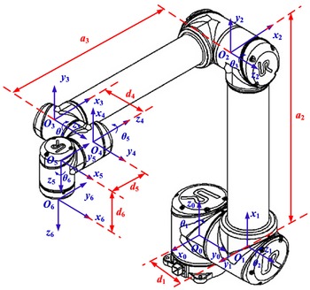
UR10 structure and kinematic coordinate system model.

2. The establishment of kinematics model of robot
The D-H parameter method is used to establish the kinematics coordinate system for UR10 robot. UR10 is an industrial robot launched by the Danish Universal Robots Company in 2012. We use the UR10 robot for joint fault diagnosis research. First, established the coordinate system of each link in the robot. Then established the motion coordinate system of each joint of the UR10 of each joint of the robot according to the principle of coordinate system establishment, so as to visually display the motion relationship between each joint of the robot. The structure and kinematic coordinate system of the UR10 are shown in Fig. 1.
Homogeneous transformation matrix expression between adjacent link coordinate systems as
 \begin{align} {}^{i-1}{}_{\!\!i}{T} & =\textrm{Rot}_{{z_{i-1}}}(\theta _{i})\cdot \textrm{Trans}_{{z_{i-1}}}(d_{i})\cdot \textrm{Trans}_{{x_{i}}}(a_{i})\cdot {\textrm{Rot}_{{x_{i-1}}}}(\alpha _{i}) \nonumber \\ &=\left[\begin{array}{c@{\quad}c@{\quad}c@{\quad}c} \cos \theta _{\textrm{i}} & -\sin \theta _{\textrm{i}}\cos \alpha _{\textrm{i}} & \sin \theta _{\textrm{i}}\sin \alpha _{\textrm{i}} & a_{i}\cos \theta _{\textrm{i}} \\[5pt] \sin \theta _{\textrm{i}} & \cos \theta _{\textrm{i}}\cos \alpha _{\textrm{i}} & -\cos \theta _{\textrm{i}}\sin \alpha _{\textrm{i}} & a_{i}\sin \theta _{\textrm{i}}\\[5pt] 0 & \sin \alpha _{\textrm{i}} & \cos \alpha _{\textrm{i}} & d_{i}\\[5pt] 0 & 0 & 0 & 1 \end{array}\right] \end{align}
In the formula (1), a
i
represent the length of the connecting rod, which is defined as the distance from Z
i−1 to Z
i
, and is positive along the X
i
axes. α
i
represent the angle of the connecting rod, which is defined as the angle from Z
i−1 to Z
i
. d
i
represent the joint offset, which is defined as the distance from X
i−1 to X
i
.
 $\theta i$
represent the joint angle, which is defined as the angle from X
i−1 to X
i
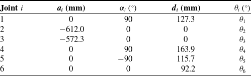
. The homogeneous transformation matrix between the robot end-effector coordinate system and the robot base coordinate system is shown in the formula (2). Table I is the theoretical D-H parameter of the robot UR10.
 \begin{equation} T_{6}^{0}=T_{1}^{0}T_{2}^{1}T_{3}^{2}T_{4}^{3}T_{5}^{4}T_{6}^{5} \end{equation}
3. The joint fault diagnosis method for robot
3.1. BP neural network model
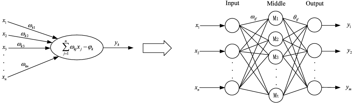
The fault diagnosis method based on artificial neural network has high adaptability, self-learning ability, and strong fault tolerance [Reference Xu, Cao, Zhou and Gao19]. In this paper, we use BP neural network as the algorithm support for fault diagnosis. The structure of the BP neural network is shown in Fig. 2, including the input layer, middle layer, and output layer.
For the neuron i, if
 $\left[x_{1},x_{2},x_{3},\ldots,x_{n}\right]$
is the external input,
 $\omega _{k1},\omega _{k2},\omega _{k3},\ldots,\omega _{kn}$
is the weight, the linear weighted summation is usually used as the net input of neurons, as shown in the formula:
 \begin{equation} \textrm{Net}_{jn}=\sum _{j=1}^{n}\omega _{kj}\cdot x_{j} \end{equation}
 $\varphi _{kj}$
represent the threshold value of the neuron. In this paper, the Sigmoid function is used as the activation function, the definition formula of the Sigmoid function is as follows:
 \begin{equation} f=\frac{1}{1+e^{-x}} \end{equation}
DH parameters of UR10.

Structure of BP neural network.

Through the threshold discrimination and activation function of neurons, the output of neurons as
 \begin{equation} y_{j}=f\left(\textrm{Net}_{jn}=\sum _{j=1}^{n}\omega _{kj}\cdot x_{j}-\varphi _{j}\right) \end{equation}
If the output of the neural network is the
 $m$
dimension vector
 $Y_{k}=\left({y_{1}}^{k},{y_{2}}^{k},{y_{3}}^{k},\ldots,{y_{m}}^{k}\right)$
, and the
 $T_{j}^{k}$
is the target value. The error of the output results is expressed by the least square method as follows:
 \begin{equation} E_{k}=\frac{1}{2}\sum _{j=1}^{m}\left(y_{j}^{k}-T_{j}^{k}\right)^{2} \end{equation}
According to the gradient descent method can be obtained:
-
(1) The parameter adjustment from the middle layer to the output layer is
(7) \begin{equation} \Delta{\theta}_{jh}=-\lambda\frac{\partial{E_{k}}}{\partial\theta_{jh}}=-\lambda\sum_{j=1}^{m}(y^{k}_{j}-T^{k}_{j})\cdot Y_{j}\cdot(1-Y_{j})\cdot\sum^{t}_{j=1}\,f(\alpha_{h}-\lambda_{h}) \end{equation}
-
(2) The parameter adjustment from the input layer to the middle layer is
(8)
\begin{equation} \Delta\omega_{ih} = -\lambda \frac{\partial{E_{k}}}{\partial\omega_{ih}} = -\lambda \left(\sum_{j=1}^{m}(y_{j}^{k}-T_{j}^{k})\cdot \dot{f}(\beta_{j}-\phi_{j})\cdot \theta_{jh}\right)\cdot \dot{f}(\alpha_{h}-\lambda_{h})\cdot\sum^{n}_{i}x_{i}\end{equation}


In formulas (7) and (8),
 $\omega _{ih}$
is the weight of the input layer neurons to the middle layer neurons,
 $\lambda _{h}$
is the threshold of the neurons in the middle layer,
 $\theta _{jh}$
is the weight of the middle layer neurons to the output layer neurons, and
 $\varphi _{j}$
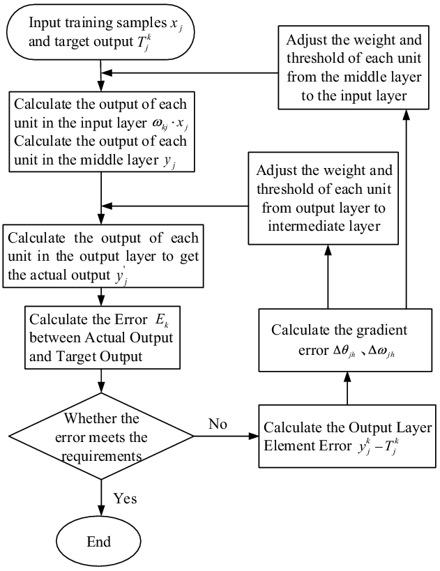
is the threshold of the output layer neurons. The training flow chart of BP neural network is shown in Fig. 3.
BP neural network training flow chart.

3.2. Establishment of joint fault database
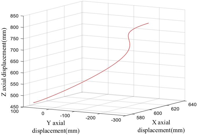
According to the actual processing movement process of the robot on the production line, the end motion trajectory of a robot is determined as the research object, as shown in Fig. 4, and the motion time
 $T = 4\,\textrm{s}$
.
Initial end trajectory of robot.

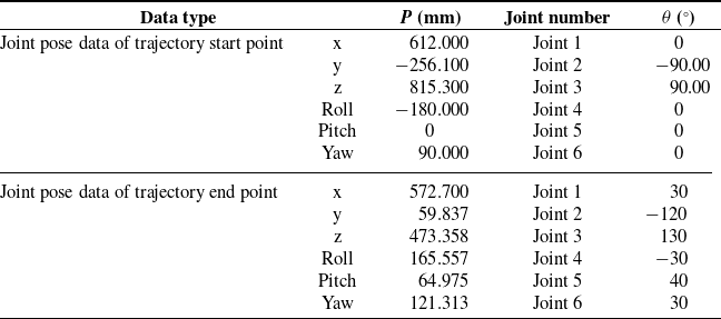
The end pose corresponding to the two limit positions of the start point and the end point of the robot end trajectory is shown in Table II.
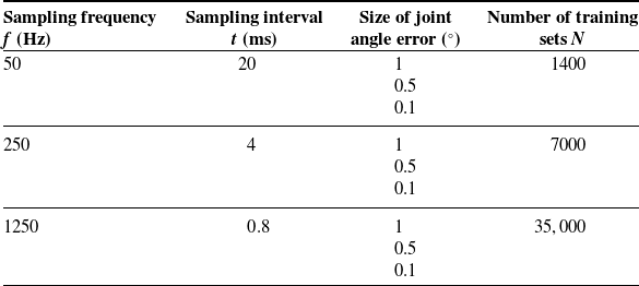
The end pose data collected in the process of robot motion are processed by injecting angle errors, and the influence of the joint angle errors and training set number on joint fault diagnosis of robot are studied. Different number of training sets can be obtained by changing the sampling frequency during the robot movement. By changing the size of joint angle error injected into the faulty joint to achieve different degree of joint angle faults. The specific research classification is shown in Table III, the number of training groups is as follows:
 \begin{equation} N=T\cdot f \end{equation}
In refs. [Reference Yang, Jin, Han, Zhao and Hu14] and [Reference Jia, Li and Chen18], the conclusion that the factors of rod flexibility, joint flexibility, and joint gap will affect the joint rotation angle was proposed. However, these factors are difficult to be quantitatively analyzed. Therefore, only the constant offset of the joint angle was considered in the simulations and experiments. In this paper, the constant offset of the joint angle is the result of comprehensive consideration of joint angle error, joint clearance, rod flexibility factor, and joint flexibility factor. The joint angle error in this paper is not a single robot control angle error.
Initial and final position and joint angle data of the trajectory.

Specific research classification.

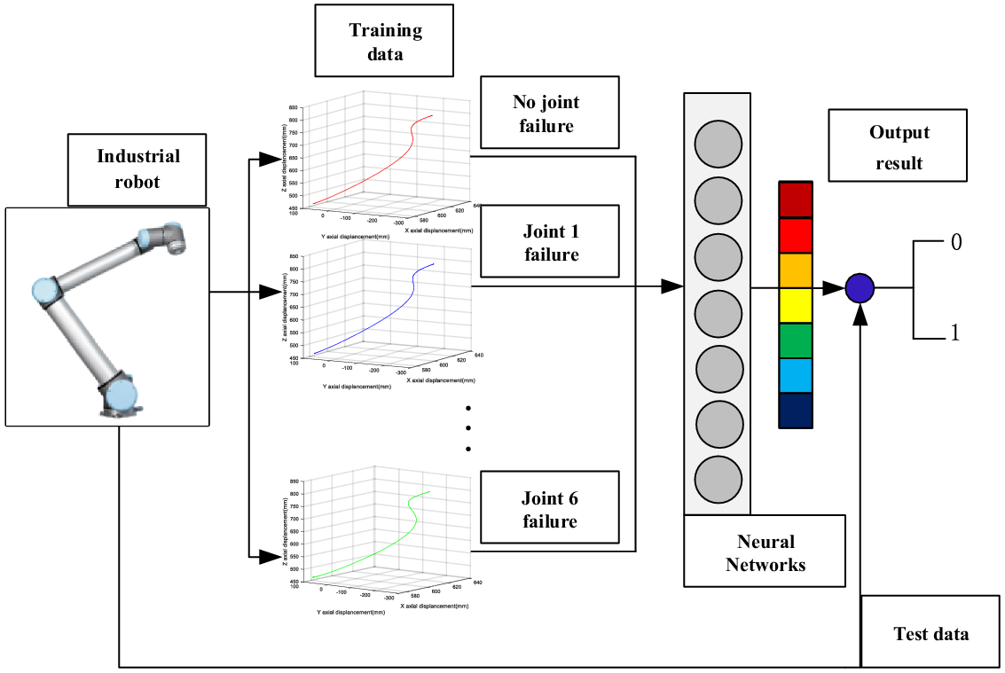
Flow chart of neural network fault diagnosis for robots.

3.3. The process of robot joint fault diagnosis method
The BP neural network model for robot joint fault diagnosis is established in Matlab, as shown in Fig. 5. The number of neurons in the middle layer is 13. The end position and end attitude data of the UR10 robot generated by the joint deviation data and unbiased data are used as the input samples of the neural network, and the training samples accounts for 70% of the total samples, the proportion of cross-validation samples is 15%, and the proportion of test samples is 15%. The output set is a series of 0 and 1 [Reference Pu, Diego and Vinicio20, Reference Jaber and Bicker21]. If the test result indicates that there is no fault in the robot, output R 0 . If the test results indicates that the joint 1 has an angle error, output R 1 . If the test results indicates that the joint 2 has an angle error, output R 2 , and so on, R 0∼6 as shown in formula (10).
 \begin{align} Ri&=r_{i}\!\left(M\right)\nonumber \\[5pt] M&=\left[\begin{array}{c@{\quad}c@{\quad}c@{\quad}c@{\quad}c@{\quad}c} 0 & 0 & 0 & 0 & 0 & 0 \\[5pt] 1 & 0 & 0 & 0 & 0 & 0 \\[5pt] 0 & 1 & 0 & 0 & 0 & 0\\[5pt] 0 & 0 & 1 & 0 & 0 & 0\\[5pt] 0 & 0 & 0 & 1 & 0 & 0\\[5pt] 0 & 0 & 0 & 0 & 1 & 0\\[5pt] 0 & 0 & 0 & 0 & 0 & 1 \end{array}\right] \end{align}
4. Simulation verification of joint fault diagnosis method for robotic arm
4.1. Simulation results of robot joint fault diagnosis based on BP neural network
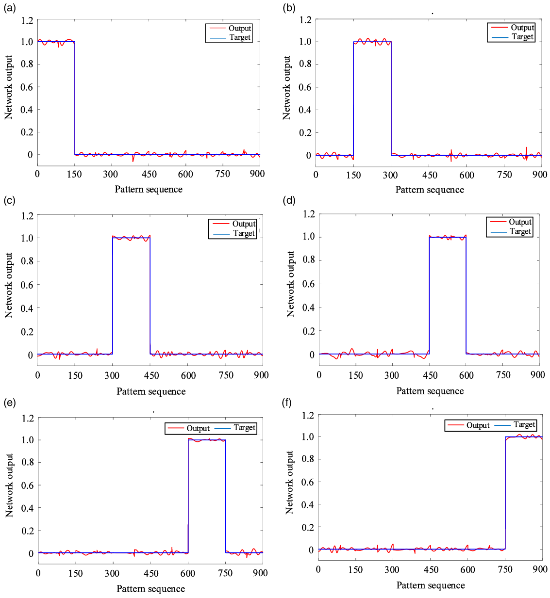
The BP neural network is trained based on the fault database of robot end pose. The fault diagnosis results of robot joints with the fault degree of 0.5° in the training set of 7000 groups are shown in Fig. 6. The number of input samples for each joint errors is 7000 groups. Each group includes the X-axis, Y-axis, Z-axis coordinates and the rotation angles of X-axis, Y-axis, and Z-axis. In the input sample, there are 1000 groups of the end pose data without joint errors, and the errors of joints 1–6 are totally 6000 groups of data. If the output result is closer to 1, it means that the failure probability of the joint is higher, and if the output result is closer to 0, it means that the failure probability of the joint is lower. And the training data accounted for 70%, the validation data accounted for 15%, the test data accounted for 15%. The calculation formula of fault diagnosis accuracy of each joint as (11). The comprehensive accuracy of fault diagnosis is the arithmetical mean value of six joint fault diagnosis accuracy as (12).
Fault diagnosis neural network outputs with 7000 training sets and angle error of 0.5°. (a) Joint 1 angle error 0.5° fault diagnosis. (b) Joint 2 angle error 0.5° fault diagnosis. (c) Joint 3 angle error 0.5° fault diagnosis. (d) Joint 4 angle error 0.5° fault diagnosis. (e) Joint 5 angle error 0.5° fault diagnosis. (f) Joint 6 angle error 0.5° fault diagnosis.

 \begin{equation} \lambda _{j}=1-E_{j}=1-\frac{1}{2mn}\sum _{k=1}^{m}\sum _{i=1}^{n}\left({y_{i}}^{k}-{\textrm{Target}_{i}}^{k}\right)^{2} \end{equation}
 \begin{equation} \psi =\frac{1}{6}\sum _{j=1}^{6}\lambda _{j} \end{equation}
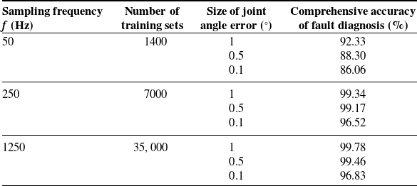
The comprehensive simulation results of joint fault diagnosis are shown in Table IV. When the sampling frequency is 50 Hz, the diagnosis accuracy of angle error 1° is 92.33%, the diagnosis accuracy of angle error 0.5° is 88.30%, and the diagnosis accuracy of angle error 0.1° is 86.06%. When the sampling frequency is 250 Hz, the diagnosis accuracy of angle error 1° is 99.34%, the diagnosis accuracy of angle error 0.5° is 99.17%, and the diagnosis accuracy of angle error 0.1° is 96.52%. When the sampling frequency is 1250 Hz, the diagnosis accuracy of angle error 1° is 99.78%, the diagnosis accuracy of angle error 0.5° is 99.46%, and the fault diagnosis accuracy of angle error 0.1° is 96.83%.
Comprehensive simulation results of joint fault diagnosis for robots.

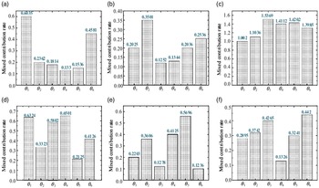
In ref. [Reference Hong, Sun, Zou and Long15], The Kernel Principal Component Analysis (KPCA) method was used to perform joint fault diagnosis, which is a kind of data-driven method. Injected 1° joint angle error into each joint separately to get joint fault database. When the KPCA output joint angle comprehensive contribution rate is higher, then it shows that the greater the probability of joint failure, the diagnosis results of the six joint failures are shown in Fig. 7.
Joint angle fault diagnosis result based on KPCA method [Reference Hong, Sun, Zou and Long15]. (a) Joint 1 diagnostic results. (b) Joint 2 diagnostic results. (c) Joint 3 diagnostic results. (d) Joint 4 diagnostic results. (e) Joint 5 diagnostic results. (f) Joint 6 diagnostic results.

We can see that the KPCA method has some effects on the fault diagnosis of robot joints, but the difference in the output results of the fault diagnosis of each joint is small, the accuracy of the diagnosis is not very high. In this paper, we used BP neural network for joint fault diagnosis, and the accuracy of joint fault diagnosis has been significantly improved, and in the case of smaller joint error like 0.1°, the BP neural network method still has high accuracy in joint fault diagnosis.
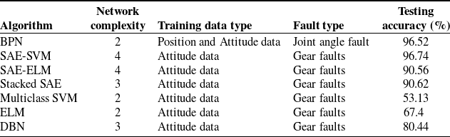
In ref. [Reference Long, Mou, Zhang, Zhang and Li22], Long proposed a SAE-SVM multijoint industrial robot transmission fault diagnosis method based on attitude data. Since the Gear faults in joint transmission system of the robot will lead to the attitude deviation of the robot end, the attitude sensor collects the attitude data of the robot in each failure mode and uses the SAE-SVM hybrid learning algorithm to build an intelligent fault diagnosis model. The results demonstrate that SAE-SVM has high accuracy, reaching 96.75%, and achieves the highest accuracy in comparison with stacking SAE, multiclass SVM, ELM, DBN and SAE-ELM. In this paper, the BP neural network is used to perform fault diagnosis based on the robot end position and attitude data, and the comprehensive accuracy reaches 96.52%. Compared with the method in ref. [Reference Long, Mou, Zhang, Zhang and Li22], it also achieves a high accuracy while reducing the network complexity, which is effective and efficient. The comparison results of each algorithm are shown in Table V.
4.2. The comparison between the BP neural network and the inverse kinematics method
4.2.1. The measurement error of end pose is not considered
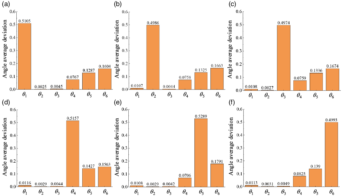
Under the condition of 250 Hz sampling frequency and 0.5° error of joint angle, we collected 1000 groups of robot end pose data corresponding to each joint angle error and extracted 100 groups of end pose data at intervals of 10 groups for inverse kinematics solution. We compared the deviation between the joint angle solved by inverse kinematics method and the initial joint angle, and the angle average deviation results are shown in Fig. 8. The results show that in the condition of only considering the rotation angle error without measurement error, the joint angle fault can be judged by comparing the data of the fault joint angle solved by the inverse kinematics method with the initial joint angle. The BP neural network and inverse kinematics solution can estimate the joint angle error without considering the measurement error of the end pose.
4.2.2. The measurement error of end pose is considered
In practical applications, the position and attitude of the robot terminal are measured by sensors (such as visual sensors). The measurement error of sensor is inevitable. The error of attitude data will affect the result of inverse kinematics solution. To assess this impact, we performed a simulation analysis. Under the condition of 250 Hz sampling frequency and 0.5° error of joint angle, we collected 1000 groups of robot end pose data corresponding to each joint angle error and extracted 100 groups of end pose data at intervals of 10 groups for inverse kinematics solution. The composition of the end pose data of each group of measurements as shown in formula (13) is
 \begin{equation} P=[P_{x} \quad P_{y}\quad P_{z} \quad \alpha \quad \beta \quad \gamma ] \end{equation}
Comparisons of each fault diagnosis algorithms.

The angle average deviation results of each joint solved by inverse kinematics. (a) Joint 1 fault inverse kinematics results. (b) Joint 2 fault inverse kinematics results. (c) Joint 3 fault inverse kinematics results. (d) Joint 4 fault inverse kinematics results. (e) Joint 5 fault inverse kinematics results. (f) Joint 6 fault inverse kinematics results.

In formula (13), P
x
, P
y,
and P
z
represent the position data on the x-axis, y-axis, and z-axis respectively, and
 $\alpha, \beta$
, and
 $\gamma$
represent the attitude angle data on the x-axis, y-axis, and z-axis, respectively.
Given the 0.5° error of z-axis attitude angle
 $\gamma$
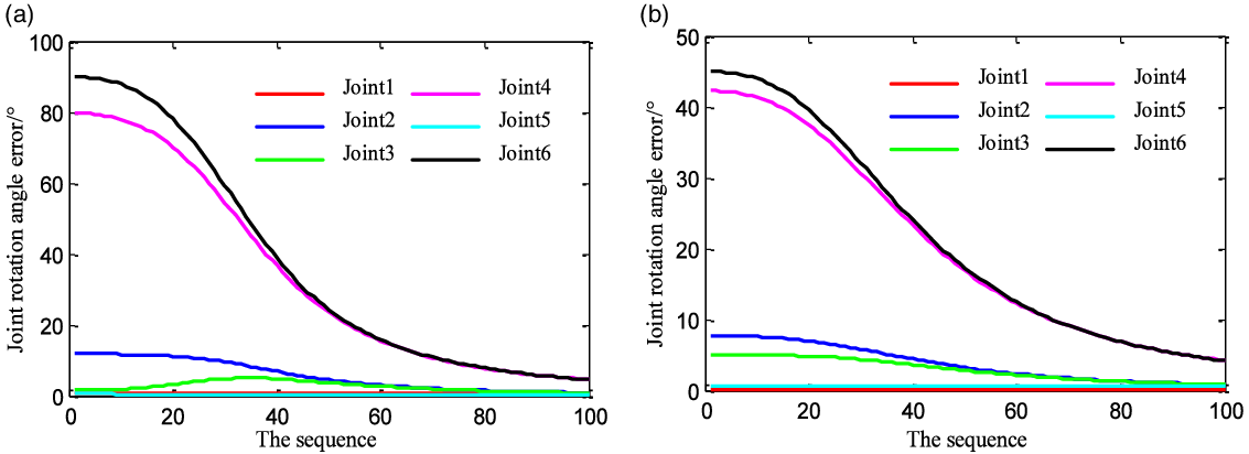
of the robot end pose data to simulate the measurement error, the joint angle deviation results solved by inverse kinematics are shown in Fig. 9. The results show that the joint angle obtained by inverse kinematics solution has a large deviation from the actual given joint angle error value. In that case, it is invalid to obtain the fault joint by using inverse kinematic solution.
The angle deviation results of each joint solved by inverse kinematics in the presence of measurement error. (a) Given a 0.5° rotation angle error of the joint 1. (b) Given a 0.5° rotation angle error of the joint 5.

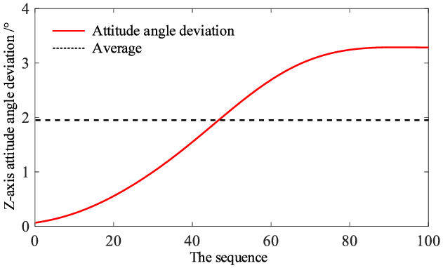
Take joint 5 as an example, the z-axis attitude angle deviation of the end pose during the robot motion in the state of 0.5° angle error is shown in Fig. 10. The average deviation of z-axis attitude angle
 $\gamma$
is 1.95°, which is greater than the measurement error of z-axis attitude angle.
The deviation of z-axis attitude angle
 $\gamma$
caused by joint 5 angle error.

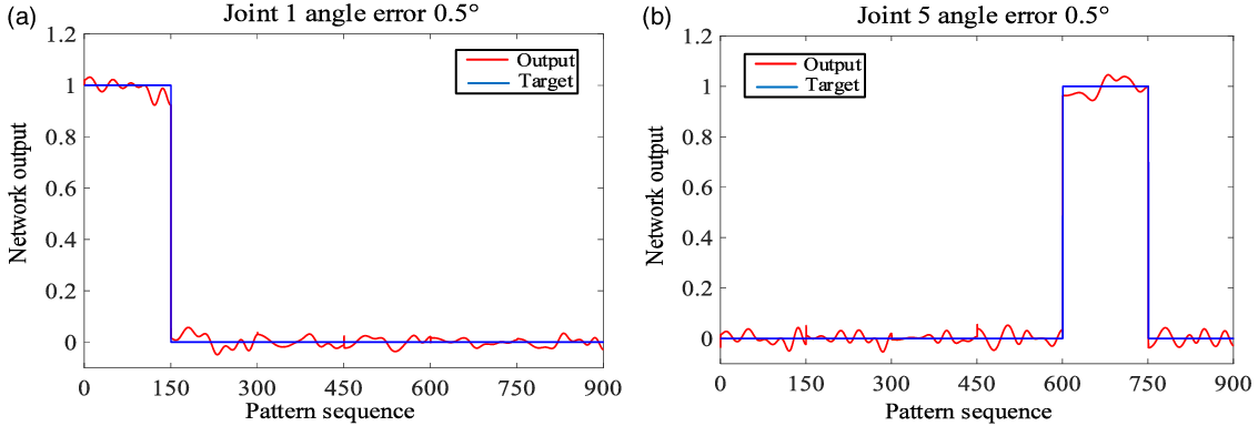
As a comparison, the BP neural network after training is used to diagnose joint faults, and the end pose data with measurement error of z-axis attitude angle
 $\gamma$
are used for test, and the results are shown in Fig. 11. The results show that BP neural network can accurately detect the faulty joints in the presence of the measurement error of end pose.
The test output of joint fault diagnosis by BP neural network in the presence of measurement error. (a) The test output of joint 1 with 0.5° measurement error of z-axis attitude angle. (b) The test output of joint 5 with 0.5° measurement error of z-axis attitude angle.

To further investigate the effect of measurement error on the fault diagnosis of the neural network method, the constant z-axis attitude angle error was replaced with three-axis position data random error and three-axis attitude angle random error, the random error obeying the normal distribution of (0.5, 0.1). The results of test output by BP neural network in the presence of random measurement errors are shown in Fig. 12. In the case of random measurement error in the end pose, some fluctuations are caused to the neural network test output results, but in general, the neural network method still has the utility of joint fault diagnosis.
The test output of joint fault diagnosis by BP neural network in the presence of random measurement errors. (a) The test output of joint 1 with normally distributed pose measurement error. (b) The test output of joint 5 with normally distributed pose measurement error.

Experimental platform for joint fault.

Diagram of robot coordinate transformation.

Signal acquisition interface and sampling frequency setting of the trinocular camera.

Compared with the inverse kinematics method, the BP neural network method has better adaptability and robustness for robot joint fault diagnosis. In addition, the accuracy of the robot end pose is affected by many factors, such as the flexible factors, which will not only affect the kinematic parameter of joint angle in the robot’s motion but also affect the kinematic parameters such as joint offset d and link angle
 $\alpha$
. When the kinematic parameters change slightly, the joint angle obtained by inverse kinematics cannot reflect the actual joint angle of the robot. In this condition, the inverse kinematics method is not suitable for joint fault diagnosis.
4.3. Analysis of robot joint fault diagnosis simulation results
Compared with traditional data-driven methods, using BP neural network for robot fault diagnosis has higher accuracy. And compared with existing machine learning fault diagnosis methods, using BP neural network also has high accuracy while reducing network complexity. Relative to the inverse kinematics method, the BP neural network has better adaptability and robustness for robot joint fault diagnosis.
When the sampling frequency is constant, the accuracy of robot joint fault diagnosis decreases with the reduction of the given fault joint angle degree. When the sampling frequency reaches 250 Hz, the comprehensive accuracy of fault diagnosis of 0.5° joint error is 99.17%, which is greatly improved compared with the accuracy when the sampling frequency is 50 Hz. When the sampling frequency exceeds 250 Hz, the comprehensive accuracy of fault diagnosis is not significantly improved with the increase of training set.
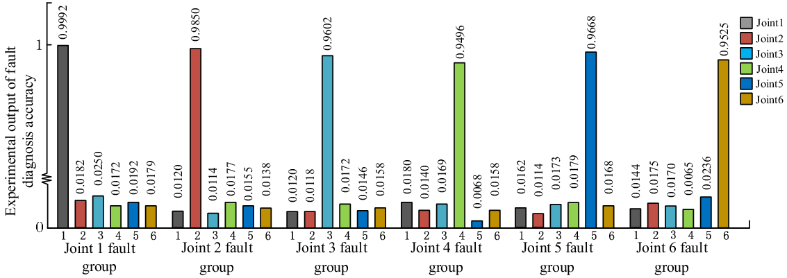
Experimental results of fault diagnosis with 0.5° joint angle error at 250 Hz sampling frequency.

We can see that different angle errors of joint and different sampling frequencies of end pose have regular effects on the accuracy of robot joint fault diagnosis. With a higher sampling frequency, more end position and attitude data can be obtained in the same trajectory, which can increase the data volume of the fault database and ultimately improve the accuracy of fault diagnosis. However, due to the limitation of the network’s ability to extract data features, the accuracy of fault diagnosis will not increase indefinitely as the amount of data increases, and a larger amount of data will greatly increase the time for neural network training. According to the results of the simulations, we give the recommended trajectory sampling frequency range for joint fault diagnosis of UR10 robot using BP neural network, which is about 250 Hz.
5. Robot joint angle fault diagnosis experiment
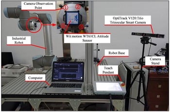
In order to verify the advantages of the proposed robot joint fault diagnosis method, a robot joint fault diagnosis test platform was established, as shown in Fig. 13. The test platform includes a 6-axial industrial robot (UR10), a trinocular smart camera (optitrack V120:Trio), four camera observation points, an attitude sensor (WT61CL), and a laptop (K501b, Asus). It should be noted that the UR10 industrial robot used in the experiment has no fault, and it meets the accuracy requirements in the repeated positioning accuracy test. In the process of collecting joint fault data, we simulated joint faults by changing the commanded positions of the robot joints.
Optitrack V120:Trio intelligent trinocular camera was used to measure and collect the position data of UR10 robot, the robot end fixed four camera observation points. The wit motion WT61CL attitude sensor is used to measure and collect the robot end attitude data. The intelligent camera and robot communicate with the computer through TCP/IP protocol and control the movement of each joint through the computer.
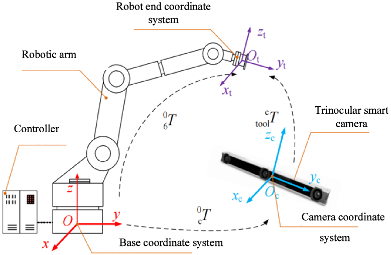
The intelligent camera and attitude sensor are used to measure and collect the position and attitude data of the end of the robot in real time. The camera acquisition frequency is set to 250 Hz, and the collected end pose data are saved in the computer. The pose data collected by the sensor and the actual pose data of the robot end are transformed as shown in Fig. 14, and the end pose matrix in the camera coordinate system is T c , the transformation matrix of the industrial robot base coordinate system relative to the camera coordinate system is T as formula (14). The actual pose data transformation matrix of the robot end is calculated as formula (15).
 \begin{equation} T=\left[\begin{array}{c@{\quad}c@{\quad}c@{\quad}c} -0.7548 & -0.6395 & -0.1459 & 287.0956\\[5pt] 0.5397 & -0.7319 & 0.4160 & -529.8563\\[5pt] -0.3729 & 0.23353 & 0.8976 & 257.4139\\[5pt] 0 & 0 & 0 & 1 \end{array}\right] \end{equation}
 \begin{equation} T_{\textrm{c}}=T\cdot {_{6}^{0}}{T}{}\cdot {_\textrm{tool}^{6}}{T}{} \end{equation}
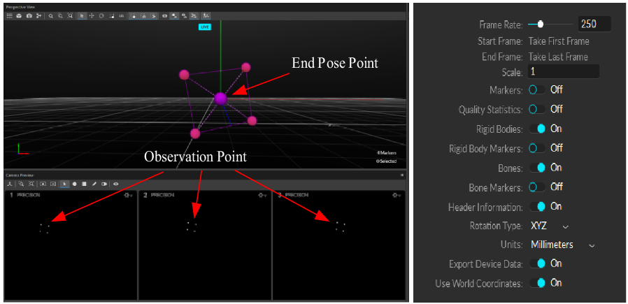
First, the pose data of the end of the robot in the process of motion without joint fault were recorded. Then, each joint was injected with an angle error of 0.5°, and the end position and attitude data were measured and recorded under the same trajectory. The signal acquisition interface and sampling frequency setting of the trinocular camera are shown in Fig. 15.
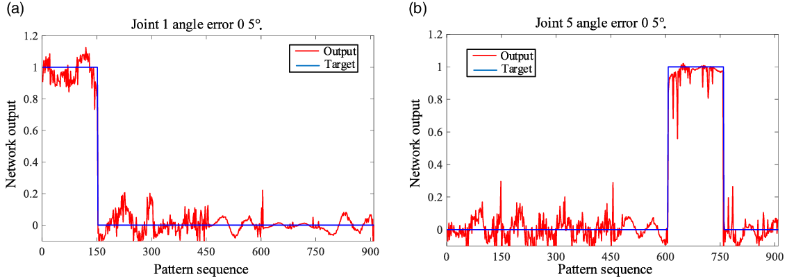
The angle error of 0.5° is injected into each joint, and the end position and attitude data are collected to establish a fault database, the fault database including six sets of end pose data generated by each fault joint. The collected fault database is tested by the trained BP neural network, and the results are output to verify the effectiveness of the neural network fault diagnosis model. The experimental output results of robot joint fault diagnosis accuracy are shown in Fig. 16. The comprehensive accuracy of fault diagnosis with 0.5° joint angle error at 250 Hz sampling frequency is 97.87%.
6. Conclusion
In this paper, the kinematics analysis of the UR10 robotic arm was performed, and the database of joint fault was established according to the end posture and joint angle of the robot in the process of motion. The BP neural network algorithm was used to study the joint fault diagnosis of the robot. The trained BP neural network model was used for joint fault diagnosis. The conclusions are as follows:
-
1. Compared with traditional data-driven methods and inverse kinematics methods, the BP neural network method has better adaptability and robustness for robot joint fault diagnosis. When the measurement error of the end pose is taken into account, BP neural network method is still suitable for joint fault diagnosis.
-
2. The influence of sampling frequency on joint fault diagnosis accuracy was analyzed. Under the same angle error, the comprehensive accuracy of fault diagnosis based on BP neural network will be improved with the increase of sampling frequency. When the sampling frequency reaches 250 Hz, the accuracy of fault diagnosis is the highest.
In the future, the influence of rod flexibility, joint flexibility and joint gap on the kinematics parameters will be considered, so as to achieve a more comprehensive joint fault diagnosis.
Conflicts of interest
The authors have no conflicts of interest to declare.
Financial support
This work is supported by the National Key R&D Program of China (2018YFB1308100), Zhejiang Provincial Natural Science Foundation under Grant LQ21F020026, Science foundation of Zhejiang Sci-Tech University (ZSTU) under Grant No. 19022104-Y. General Scientific Research Project of Zhejiang Provincial Department of Education (Grant Nos.19020038-F, 19020033-F). National Natural Science Foundation (Grant 51375458). Beijing Satellite Environmental Engineering Research Institute (CAST-BISEE2019-001).
Author contributions
Ming Hu and Jing Yang conceived and designed the study. Jianguo Wu and Jing Yang wrote the article. Lijian Zhang and Fan Yang conducted data gathering.