
Introduction
End-stage renal disease (ESRD) is the last stage of chronic renal failure. Specifically, the glomerular filtration rate (GFR) has dropped to a critically low level and the kidney can no longer act as an effective filter that retains vital biomolecules while letting metabolic wastes pass through for subsequent excretion from the body.[Reference Clase1] ESRD patients often suffer from complications such as anemia, mineral and bone disorders, and uremic malnutrition.[Reference Thomas, Kanso and Sedor2] With more than 600,000 people in the USA suffering from ESRD and an annual growth of 2–4%, ESRD is a growing concern and burden on the healthcare system. Although organ transplantation replaces a dysfunctional kidney with a healthy one, the severe shortage of available donors creates a burning need for an alternative.[3, Reference Eames, Holder and Zambrano4]
Hemodialysis is a life-saving procedure that removes excess fluids and metabolic waste while maintaining the acid–base and electrolyte balance in ESRD patients’ blood.[Reference Javed, Savkin, Chan, MacKie and Lovell5] Although hemodialysis treats approximately 90% of ESRD patients and has saved millions of lives, commercially available hemodialysis devices have many disadvantages, including their bulky sizes and 3–4 h of treatments for three times a week, which decreases patient compliance and significantly decreases the patients’ quality of life.[Reference Polaschegg6–Reference Kraemer8] Furthermore, the US Renal Data System and Wolfe et al. reported that patients who receive regular hemodialysis treatments have lower life expectancies compared with those who received a kidney transplant.[Reference Wolfe, Ashby, Milford, Ojo, Ettenger, Agodoa, Held and Port9] Infections, vascular access complications, solute balance, and hemolysis are some of the factors that increase mortality risks.[Reference Kraus, Kansal, Copland, Komenda, Weinhandl, Bakris, Chan, Fluck and Burkart10, Reference Tharmaraj and Kerr11] Inadequate filtration can lead to hyperkalemia and hypokalemia that will induce sudden cardiac arrest. The fouling of dialyzer's membrane and tubing can also occur over time, which causes flow obstruction and hemolysis that can adversely affect the patients.[Reference Tharmaraj and Kerr11]
Thus, there is a critical and unmet need for new hemodialysis technologies that address at least some of the key limitations of the currently available devices and improve ESRD patient outcomes. Ideally, the new device should be portable and continuously operating, such that the patients have high freedom of movement and abilities to engage in everyday activities. Moreover, the device surfaces that are exposed to patient's blood should be antifouling, which decreases the chances of developing various medical complications. These factors will improve patients’ quality of life, ameliorate patient compliance, and decrease mortality risks.
In this work, we introduce the design concept of a compact, microfluidic hemodialysis device consisting of a glomerulus-like unit (GLU) that can potentially meet the aforementioned needs. The device was composed of two biocompatible polydimethylsiloxane (PDMS) chambers separated by a cellulose ester (CE) semi-permeable membrane. The surfaces of PDMS and CE membrane were functionalized with polyethylene glycol (PEG) polymers for the antifouling property. Using a blood-mimicking fluid (BMF) composed of urea and bovine serum albumin (BSA), we investigated the device's abilities to remove urea while retaining essential biomolecules. This work will serve as a proof of concept for a future portable hemodialysis device in which multiple GLUs can be arranged in parallel to form a clinically functional hemodialysis device.
Materials and methods
Fabrication
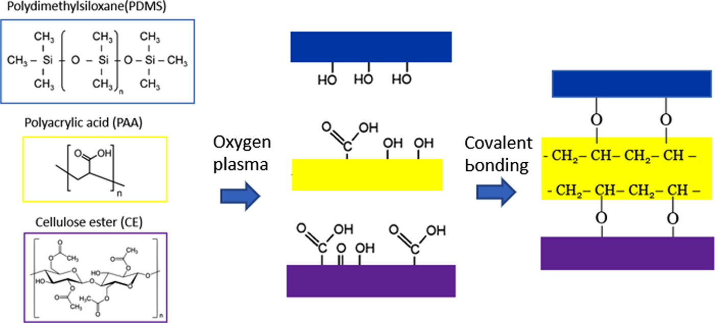
The hemodialysis device was composed of two chambers made of PDMS using the Slygard 184 Silicone Elastomer Kit. The silicone elastomer was poured into molds three-dimensional (3D)-printed by the Creater Pro Flash Forge and cured overnight at 80°C. A CE membrane (12–14 kDa MW cut-off; Spectrum Laboratories) was sandwiched between the two chambers. Binding between the PDMS and CE membrane was enhanced with plasma activation and a double-sided polyacrylic acid (PAA) adhesive (3 M). The plasma activation introduced hydroxyl and carboxyl groups on the PDMS, CE, and PAA, which induce covalent bonding. Poly(methyl methacrylate) molds were then used to hold the device together and connect the tubes and peristaltic pumps (VWR and Watson Marlow 313S).
Surface functionalization of PDMS and CE for antifouling
The PDMS and CE membranes were activated through plasma and piranha treatments, respectively, to introduce hydroxyl and carboxyl groups. The CE membrane was activated with oxygen plasma (Harrick plasma®, PDC-32G) for 1 min.[Reference Sunkara and Cho12] The PDMS was incubated in a 2:3 ratio of piranha solution (H2O2:H2SO4) for 15 min and then incubated in a 1 M potassium hydroxide (KOH) solution for another 15 min.[Reference Maji, Lahiri and Das13] Immediately after activation, both were immersed in a 10% (3-aminopropyl) triethoxysilane solution (APTES; Sigma-Aldrich) overnight at room temperature. The solvent of the 10% APTES was toluene and de-ionized (DI) water for CE and PDMS, respectively.[Reference Howarter and Youngblood14] The CE membrane was washed with copious amount of toluene and DI water while the PDMS was washed with DI water. Afterward, the APTES-functionalized components were assembled together. A steady flow of a solution comprised 2 mM 1-ethyl-3-(3-dimethylaminopropyl) carbodiimide (EDC), 5 mM N-hydroxysuccinimide (NHS), and 55 mM O-(2-carboxyethyl) PEG (3 kDa) in MES [2-(N-morpholino)ethanesulfonic acid] and PB (phosphate buffer) buffer (Sigma Aldrich) flowed for 2 h at room temperature.[Reference Hermanson15] A 10-min flow of phosphate-buffered saline (PBS) and PBS-T (PBS tween) were then used to wash off the loosely bound PEG molecules.
Antifouling analysis
Plasma platelets were extracted from the blood through a two-step process: whole blood (Bioreclamation IVT) was centrifuged at 270 g for 10 min to extract the plasma supernatant, which was then further centrifuged at 2000 g for another 10 min to collect the platelets in the pellets.[Reference Jo, Roh, Kim, Shin and Yoon16] The resulting plasma platelet was incubated with a solution of 56 mM 5,6 carboxyfluorescein (5,6 CF; Sigma Aldrich) in 10 mM HEPES [4-(2-hydroxyethyl)-1-piperazineethanesulfonic acid] buffer for 30 min in the dark at room temperature. The platelet pellet was then washed three times with PBS by centrifugation at 2000 g for 5 min each.[Reference Heger, Salles, Van Vuure, Deckmyn and Beek17] The fluorescently labeled platelets suspended in PBS were flown continuously at 1 mL/min into the device for 30 min. The device was disassembled, and surfaces of PDMS and CE membrane were imaged on Nikon Eclipse fluorescent microscope and Zeiss confocal microscope at an excitation wavelength of 495 nm. The fluorescent images were analyzed in ImageJ (NIH software) to calculate the number of platelets.
Urea clearance analysis
The BMF solution was composed of 1.4 mM BSA (66 kDa) and 20 mM urea (60.06 Da) in PBS to represent ESRD patients’ blood albumin and elevated urea concentration of 100–200 mg/dL (16.7–33.3 mM).[Reference Amin, Mahmood, Asad, Zafar and Raja18, Reference Foley, Parfrey, Harnett, Kent, Martin, Murray and Barre19] Since red blood cells have a threshold shear stress of 1500 dynes/cm3 before cell damage,[Reference Leverett, Hellums, Alfrey and Lynch20] and the device channel had a width of 500 µm and height of 800 µm, the maximum allowable flow rate before hemolysis occurs was calculated to be 25 mL/min. In this work, the BMF flow rate was set at 1.1 mL/min. A PBS solution was used as dialysate, which was introduced into the device at a flow rate of 16 mL/min in the opposite flow direction.
A urea assay kit (Sigma Aldrich) was used to measure the pre- and post-dialysis urea concentrations in the BMF. A sample of the post-dialysis BMF was taken every hour for 3 h to be analyzed. Bradford assay (Sigma Aldrich) was conducted to determine the pre- and post-dialysis BSA concentrations in the BMF. The absorbance signals from both assays were measured with the Spectramax M2e spectrophotometer (Molecular Devices Spectramax) at wavelengths of 570 and 595 nm, respectively. The following equation was used to calculate the urea clearance rate:
 $${\rm Clearance\;} (K) = Q_{\rm b} \times \displaystyle{{(C_{\rm i} - C_{\rm o})} \over {C_{\rm i}}},$$
where Q b is the blood flow rate, C i is the pre-dialysis urea concentration and C o is the post-dialysis urea concentration. The clearance rate per unit area was determined by dividing K by the exchange surface area of 102.5 mm2.
Results and discussion
Device fabrication
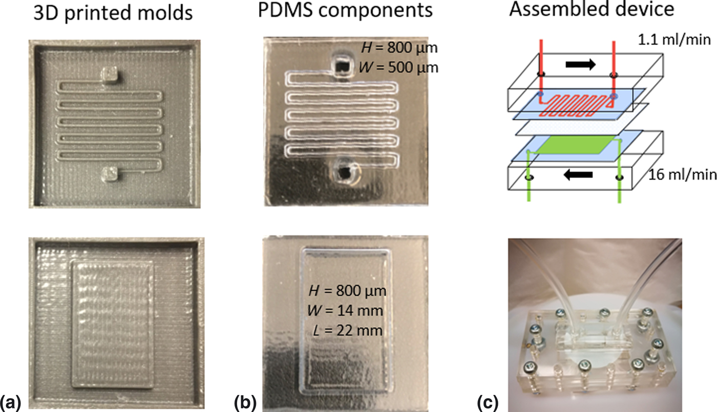
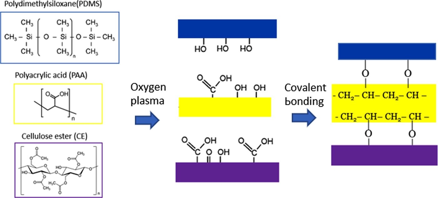
In this work, we fabricated a conceptualized hemodialysis device as a single GLU. Figure 1 shows the basic fabrication steps. Detailed procedures are presented in the “Materials and methods” section. A PAA adhesive layer was used to enhance the binding between the CE membrane and the PDMS chambers to obtain a stable leak-free device. Prior to adhesion, the PDMS, PAA, and CE surfaces were activated with oxygen plasma for covalent bonding (Fig. 2).
Microfluidic hemodialysis device fabrication steps. (a) 3D-printed molds for the upper (top) and lower (bottom) PDMS chambers. (b) The cured PDMS formed the upper channels for the BMF (top) and the lower chamber for the dialysate (bottom). (c) The schematic of the device (top) encasing a single GLU, where BMF (red) and dialysate (green) were introduced in opposite directions, and a photograph of the assembled test device (bottom).

Schematics showing the procedure for bonding of membranes in the microfluidic device. The device components were treated with oxygen plasma to introduce hydroxyl and carboxyl functional groups for covalent linkages.
Antifouling coating
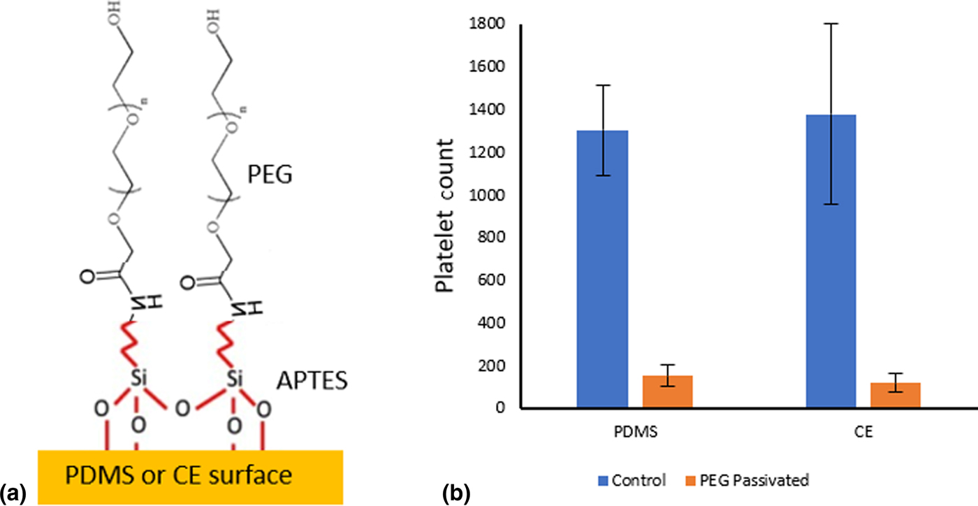
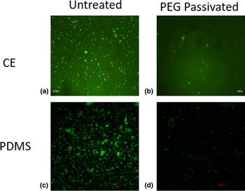
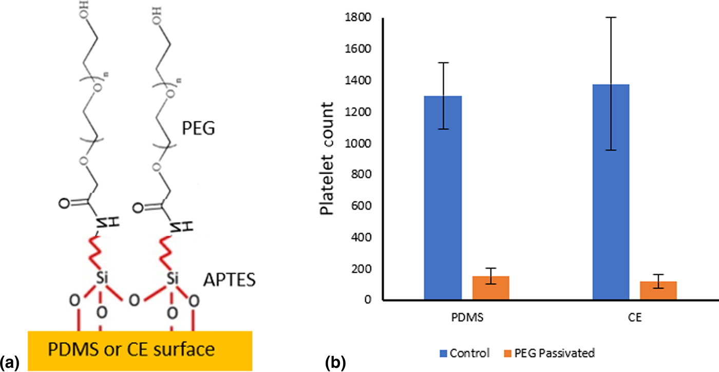
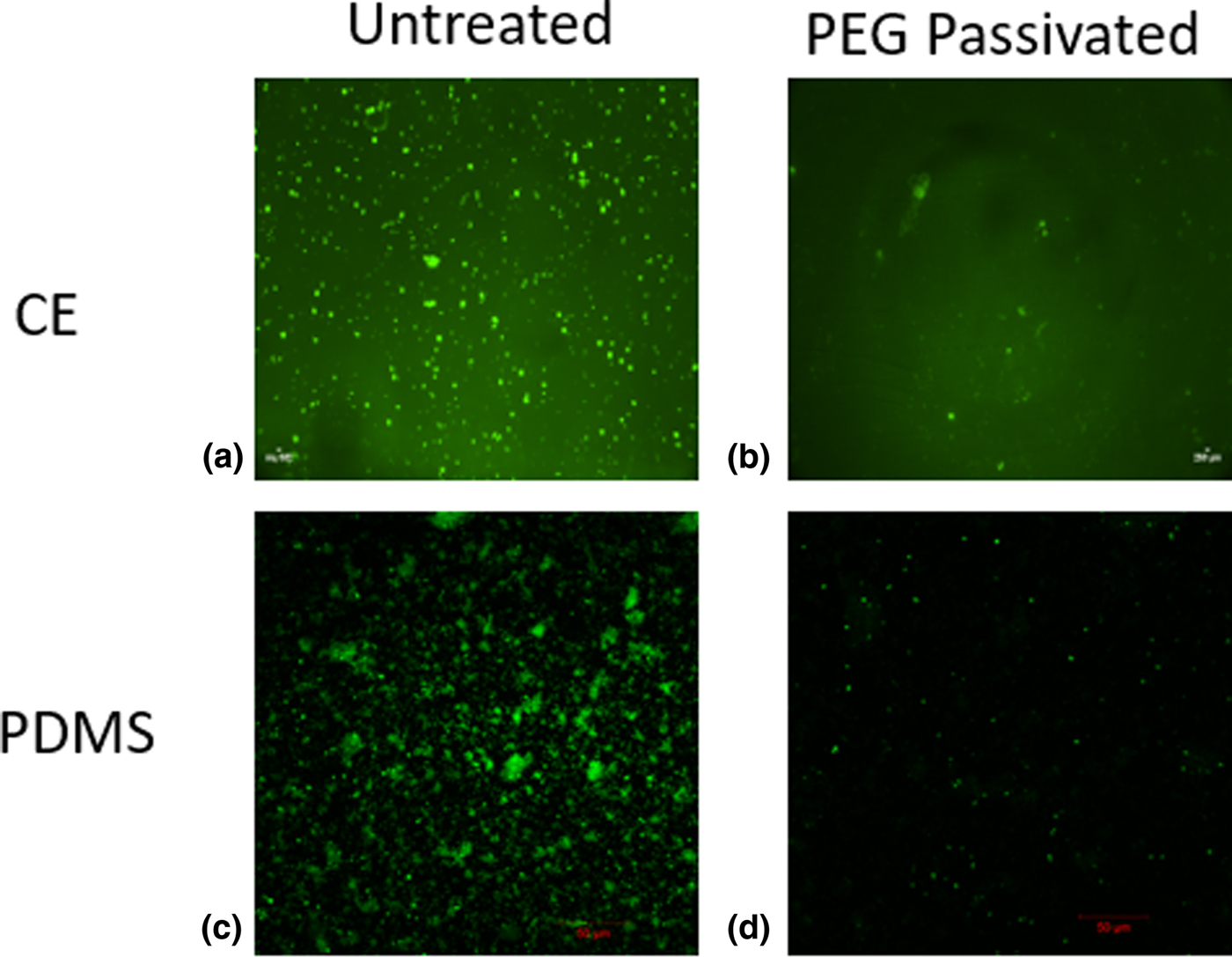
Surface fouling of the hemodialysis device causes flow obstruction in the tubing, which leads to a series of complications including clogging, hemolysis, and reduced toxin removal efficiency.[Reference Kraemer8–Reference Tharmaraj and Kerr11] To address these issues, we functionalized the surfaces of the device components with PEG polymer, which has proven effectiveness in resisting protein binding due to its ability to interact with water molecules.[Reference Banerjee, Pangule and Kane21–Reference Harder, Grunze, Dahint, Whitesides and Laibinis23] After APTES molecules were immobilized uniformly on the CE and PDMS surfaces, peptide bonds were formed between the amine group of APTES and the carboxyl group of the O-(2-carboxyethyl) PEG monomer via EDC–NHS chemistry (Fig. 3a). According to Fig. 3b, PEG-functionalized CE membrane and PDMS showed platelet count reductions of 86% (from 1378 to 117) and 74% (from 1300 to 150), respectively, compared with their untreated counterparts. Figure 4 shows fluorescent images of plasma platelets on the surfaces of PEG-treated/untreated CE membrane and PDMS. Overall, the presence of PEG film significantly decreases fouling, which would ultimately decrease the patients’ mortality risks.
Surface functionalization for antifouling. (a) Schematic representation of PEG-grafted CE membrane and PDMS surfaces. (b) Platelet counts after 30-min blood plasma incubation on untreated and PEG-passivated CE membrane and PDMS.
Fluorescent images of 5,6 CF-labeled platelets after 30 min of incubation on treated versus untreated CE and PDMS surfaces. (a, b) Untreated and PEG-passivated CE membranes. (c, d) Untreated and PEG-passivated PDMS.
Urea clearance
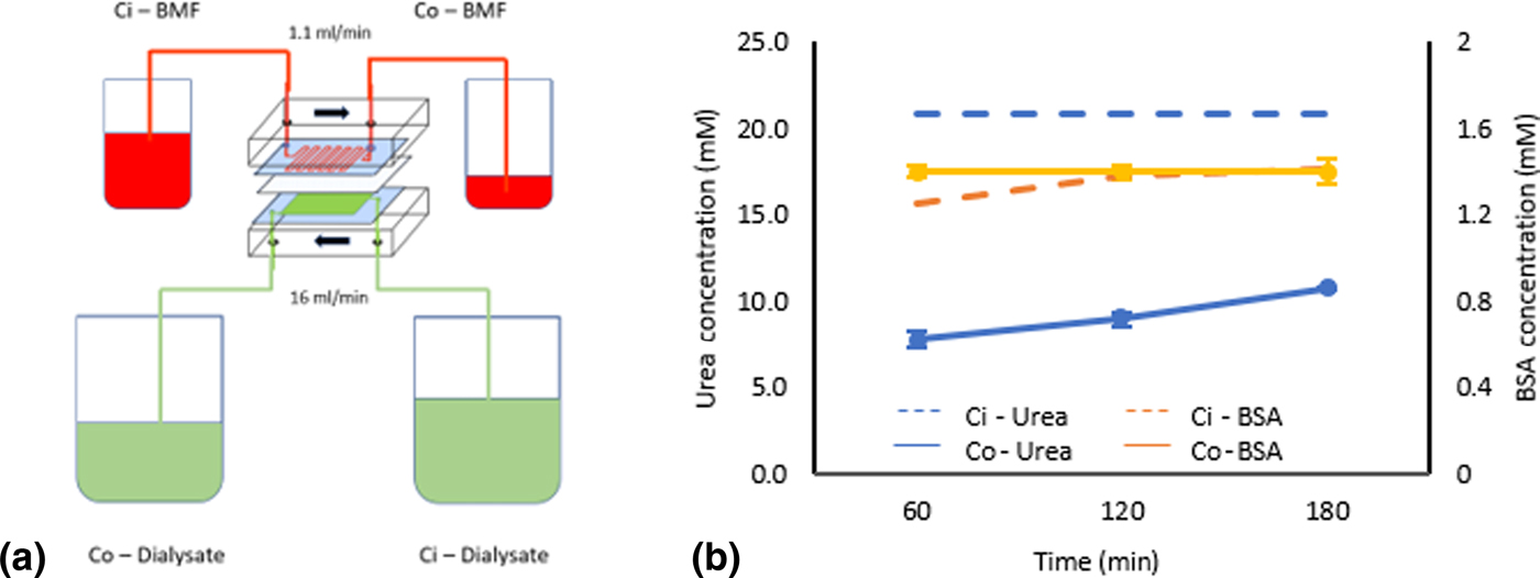
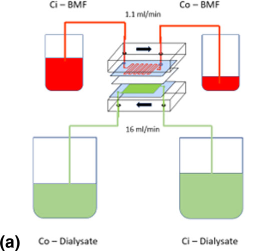
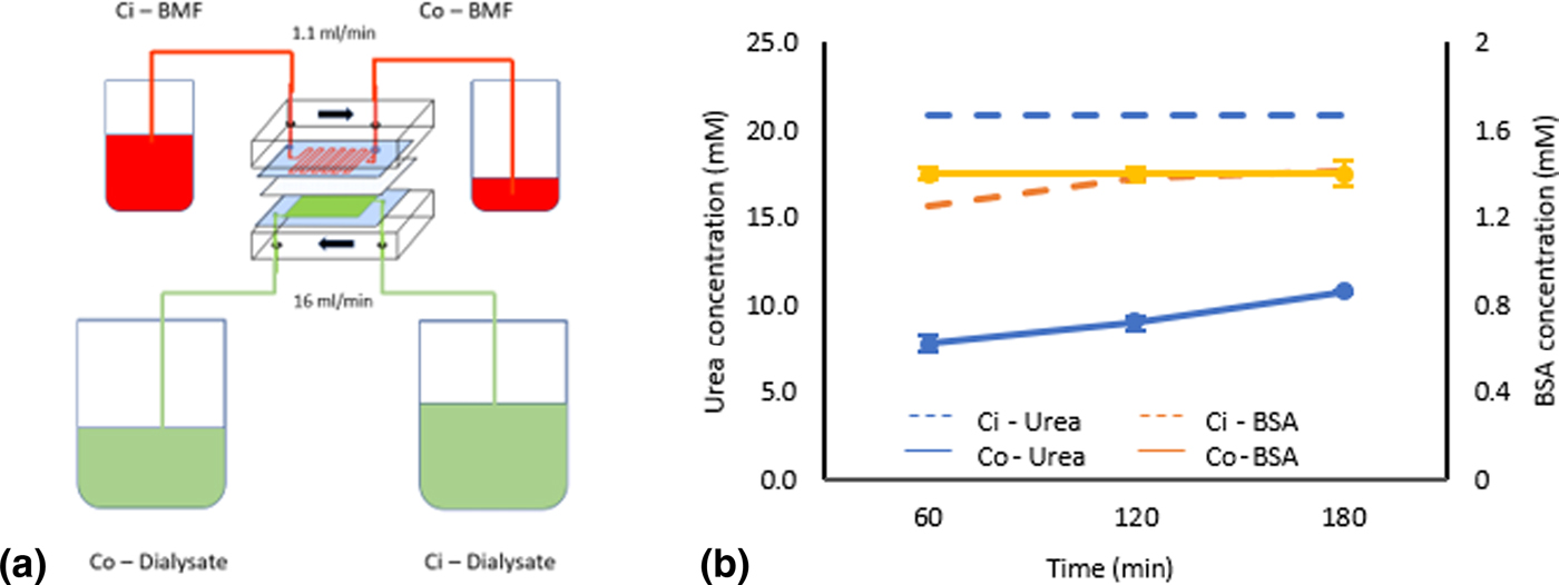
To measure urea clearance, the BMF flowed through the upper chamber while the dialysate flowed through the bottom chamber's reservoir in the opposite direction (Fig. 5a). Urea clearance rate is the most commonly used indicator for analyzing hemodialysis efficiency. According to Fig. 5b, albumin concentration before and after dialysis remained unchanged at 1.4 mM. On the other hand, the concentration of urea was initially 20 mM and remained constant at approximately 9 mM (i.e., 55% reduction) after the BMF flowed through the device during the 3-h dialysis period, indicating that our device was able to remove metabolic wastes and retain vital proteins. The normalized urea clearance per unit area in our device was calculated to be 6300 mL/min·m2, which is significantly higher than that of a healthy kidney (i.e., 794.4–1259 mL/min·m2)[Reference McPherson and Pincus24, Reference Bohle, Aeikens, Eenboom, Fronholt, Plate, Xiao, Greschniok and Wehrmann25] and the conventional dialyzer (Fresenius) (101 mL/min m2)[Reference Alayoud, Bahadi, Aatif, Benyahia, Montassir, Hamzi, Zajjari, De. Kabbaj, Maoujoud, Hassani and Oualim26]. However, since our device only represented one glomerular unit and a natural kidney has many units operating simultaneously, the overall urea clearance rate of our device (0.646 mL/min) was lower compared to a normal kidney (i.e., 41–65 mL/min)[Reference McPherson and Pincus24, Reference Bohle, Aeikens, Eenboom, Fronholt, Plate, Xiao, Greschniok and Wehrmann25] and conventional dialyser (i.e. 202 mL/min)[Reference Alayoud, Bahadi, Aatif, Benyahia, Montassir, Hamzi, Zajjari, De. Kabbaj, Maoujoud, Hassani and Oualim26]. In addition, this single-unit device exhibited a BMF flow rate of 1.1 mL/min, which was slower compared with the physiological renal blood flow of 1 L/min[Reference Eaton and Pooler27] and the average renal blood flow of conventional dialyzer of 291 mL/min[Reference Alayoud, Bahadi, Aatif, Benyahia, Montassir, Hamzi, Zajjari, De. Kabbaj, Maoujoud, Hassani and Oualim26]. Therefore for the future hemodialysis device, multiple GLUs will be assembled in parallel to improve the absolute urea clearance rate by increasing the exchange surface area and blood flow rate, as well as to better mimic the kidney's physiological structure.
Urea clearance characterization. (a) Schematic representation of the experimental setup where BMF (red) and dialysate (green) were introduced through the upper and lower chambers, respectively. (b) The pre- and post-dialysis concentrations of urea and BSA over a 3-h period.
Conclusion
In this paper, we report the design concept of a highly efficient microfluidic platform that will form the basis of a next-generation multi-GLU hemodialysis device. The fabricated device was composed of two PDMS chambers separated by a semi-permeable CE membrane, both of which were surface-functionalized with PEG polymers for the antifouling property. Using a BMF, our device was shown to be selective in removing urea while retaining vital molecules such as albumin. Furthermore, the device exhibited more than an order of magnitude higher urea clearance rate per unit area compared to a healthy kidney and a conventional dialyzer. We envision that future devices will have multiple parallel GLUs integrated, thus to increase the overall blood flow rate and clearance rate to a clinically viable range. Compact devices, which can be worn by a patient and run continuously, will potentially improve the mobility, and in general, the quality of life of ESRD patients greatly.
Acknowledgments
The authors would like to thank Dr. Dongqing Li and Dr. Michael Tam for providing access to the plasma cleaner and Watson Marlow peristaltic pumps, respectively. Also, we would like to thank Dr. Yael Simakov, Ran Peng, Yun Wu, and Andrew Wenger for their assistance with this project. This work is supported by a discovery grant from the Natural/Science and Engineering Research Council (NSERC) of Canada to Dr. Tang.