NOMENCLATURE
- CT
-
thrust coefficient (= T/ρA(ΩR)2)
- CX
-
propulsive force coefficient (= X/ρAV∞ 2)
- C PL
-
pitch link force coefficient (= PL/ρA(ΩR)2)
- C M,k
-
blade section bending moment coefficient (= Mk/ρA(ΩR)2R, k = x, y, z)
- CP
-
power coefficient (= T/ρA(ΩR)3)
- cn
-
blade section normal force coefficient
- Dij
-
design variable (I = tw, sw, dh, and j = the location of control point)
- dh
-
dihedral [deg]
- EI i
-
blade bending stiffness (i = flap or lag) [lbf-ft2]
- F jH
-
non-rotating hub forces (j = x, y, and z) [lbf]
- Kj
-
vibration index weighting factor (j = F, M)
- M jH
-
non-rotating hub moments (j = x, y, and z) [lbf-ft]
- R
-
rotor blade radius [ft]
- ri
-
radial control point (i = 1,4) [ft]
- s
-
rotor solidity (= Nb c/πR)
- sw
-
sweep [deg]
- tw
-
twist [deg]
- VI
-
vibration index
- V ∞
-
freestream velocity [ft/s]
- W 0
-
nominal aircraft weight [lbf]
- η
-
blade section horizontal coordinate
- λ
-
blade sweep angle [deg]
- μ
-
advance ratio (= V ∞/ΩR)
- ζ
-
blade section vertical coordinate
- ()0
-
before parametric design
- ()1
-
after parametric design
1.0 INTRODUCTION
Rotorcraft, with their capability to take off and land practically anywhere, have demonstrated great versatility for civilian as well as military applications. Rotorcraft encounter unique challenges compared to fixed-wing aircraft due to widely varying flight conditions at which the main rotor is operated throughout the flight envelope. Improved design of the rotor blade is a key to overcome these challenges, but is difficult due to the complex nature of the aerodynamic and structural environments in the rotorcraft operational envelope.
There have been numerous optimisation studies for rotor blades over the last three decades(Reference Lim and Chopra1-Reference Ortun, Bailly, des Rochettes and Delrieux12). The common goals of these rotor optimisation studies were a reduction of vibration and/or noise, a performance improvement or a combination of these objectives. Recent applications of high-fidelity Computational Fluid Dynamics (CFD) tools to rotorcraft have demonstrated a significant improvement in accuracy of the predictions(Reference Potsdam, Yeo and Johnson13). With improved accuracy, a number of CFD-based optimisation studies have been presented(Reference Imiela and Wilke6-Reference Ortun, Bailly, des Rochettes and Delrieux12). However, the design spaces explored in most of these optimisation studies were limited since function evaluations in CFD tools were expensive. To overcome this limitation, an adjoint method(Reference Mishra, Karthik, Mavriplis and Sitaraman10,Reference Naik, Economon, Colonno, Palacios and Alonso11) was often adopted for gradient-based constrained optimisation problems.
Another commonly used approach to lower the computation cost is to reduce the number of design variables by using a set of parametric equations(Reference Imiela and Wilke6-Reference Leon, Le Pape, Desideri, Alfano and Costes9). These parametric equations can be applied at multiple radial control points to morph the complex geometries in the passive blade design. The use of more radial control points would make the geometries of the parameterised passive rotor blade more accurate, but it substantially increases the computation time.
Imiela and Wilke(Reference Imiela and Wilke6) showed that the hover figure of merit of the EC1/EC2 rotor (5.5 m in radius) was improved by 3.7% using variations of linear twist and anhedral at two radial locations, r/R = 0.90 and tip. The results were obtained using HOST/FLOWer and the optimiser DAKOTA(Reference Adams14). The power required for the same rotor was reduced by 2.2% at 241km/h (μ = 0.33) using variations of twist, chord, sweep and anhedral at the two fixed radial control points, r/R = 0.90 and the tip (twist varied also at r/R = 0.50). In this study, structural property updates or use of constraints was not considered, so a risk of rotor blade structural failure existed.
Min et al.(Reference Min, Sankar, Collins and Brentner8) presented a parametric study for noise reduction by applying a forward-backward sweep to the HART II rotor blade. Two parameters (forward sweep radial location and a forward sweep offset) were used to represent a design change, and up to about 40° of sweep was considered. The results were obtained using GENCAS. The maximum BVI noise reduction of about 1dB was found with the best design for the descent condition (μ = 0.15). However, again, neither structural property updates nor use of constraints was considered.
Leon et al.(Reference Leon, Le Pape, Desideri, Alfano and Costes9) presented a more rigorous optimisation study with 16 design variables – twist, sweep and chord at the five fixed radial control points plus the collective pitch. Parameterisation was applied to the baseline ERATO blade configuration, and the results were obtained using HOST/elsA and the optimiser DAKOTA. The hover figure of merit was improved by 0.06 after imposing a maximum steady pitch link load (PL) limit. However, they concluded that the optimum solution found from this aerodynamic design was an unrealistic s-shaped blade, which could have been avoided by considering additional structural and flight mechanics constraints.
Ortun el al.(Reference Ortun, Bailly, des Rochettes and Delrieux12) made an attempt to include updates in the structural properties when design variables changed. Parameterisation was applied to the 7AD blade using a chord variation from r/R = 0.30 to the tip with 10 Bezier poles. The optimum design after the update to the blade structural properties was presented with a forward sweep, but no structural constraints were considered. The results were computed using HOST/elsA and DAKOTA. A 3.3% power reduction was found at 140Kn (μ = 0.36) for an optimal solution. Although a reasonable power reduction was shown, the optimal blade planform presented exhibited some room for improved blade geometries, which can be done by considering the structural design constraints.
The impact of blade structures with design changes has been frequently neglected in many rotorcraft optimisation studies. With change in typical design variables (e.g. sweep or dihedral), blade section structural properties change and, consequently, constraints such as blade stability boundaries or fatigue criteria need to be re-evaluated.
Passive rotor blade design allows blade geometries to be changed using design variables. Inclusion of realistic structural design constraints makes the feasible design space practical. The realistic structural constraints considered in this study are:
-
• Blade stability – blade damping in all modes should be positive.
-
• Steady (sectional) moments – these include the steady flap bending, lag bending and torsion moments. The maximum design limits of these steady moments are typically unknown, so the constraints are bounded by the soft margin of being not excessively violated (e.g. 35%). This assumes that an excessive design will be improved by future redesign of the blade structure via the cross-sectional analysis.
-
• UTTAS (Utility Tactical Transport Aircraft System) manoeuvre half peak-to-peak PL – The UTTAS manoeuvre is a high-g manoeuvre condition for UH-60A flight. Similar to the steady moments, the constraint is bounded by the soft margin of being not excessively violated (e.g. 20%)
Although a formal optimisation technique is not employed in this study, searching for an ad hoc optimal rotor design is attempted using a parametric study for the selected UH-60A flight condition. Significant validation efforts for the baseline UH-60A rotor are made using CAMARD II(Reference Johnson15) to increase the confidence level on findings in this study. The primary objectives of this study are (1) to test the parametric design tool for application to passive rotor design, (2) to understand the effect of design variables on the structural constraints in passive rotor design and (3) to find whether there exists a feasible design space within the structural constraints. These objectives will help establish guidelines for future applications of the optimisation methodology to rotorcraft.
2.0 PARAMETRIC DESIGN
Parametric design is applied to morph the complex geometries in the design using a reduced number of design variables by means of a set of parametric equations. The advanced blade geometries, such as British Experimental Rotor Programme (BERP)(Reference Brocklehurst and Barakos16) or BlueEdgeTM(Reference Rauch, Gervais, Cranga, Baud, Hirsch, Walter and Beaumier17), can be simulated using parametric equations with many radial control points or higher-order polynomials.
When sweep or dihedral is chosen as a design variable, the blade section will be rotated. If a rigid rotation of the blade section is made for sweep or dihedral, the blade radius will be shortened and the section chord along the free stream direction increases. Because the thickness of the aerofoil section is the same, this approach would result in a different aerofoil section. Therefore, the following design guideline is used in the parametric design process to prevent any undesired outcomes – the blade aerofoil section should remain unchanged along the free stream direction.
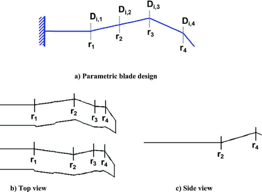
Parametric design is intended to make a change in the blade planform with the use of a reduced number of design variables. For this process, parametric equations are established to characterise complex geometries of a rotor blade planform. Figure 1(a) shows a schematic diagram of a parametric blade with design variable Di,j at the radial control point rj and the design variable Di,j is defined constant from rj to rj +1. The design variables considered are blade twist, sweep and dihedral with associated radial control points. In order to represent an unconventional or advanced blade tip geometry, up to four radial control points can be chosen in the present parametric design tool in which the design variables are varied. Thus, up to 16 design variables (three variables at the four radial control points, in addition to the locations of all four radial control points) are allowed for parametric design. Complex examples of the parametric design are shown in Fig. 1(b)-(c). In these examples, parameterisation was applied to the UH-60 blade configuration(Reference Shinoda, Norman, Jacklin, Yeo, Bernhard and Haber18) with multiple sweeps and dihedral.
Examples of parametric blade design.

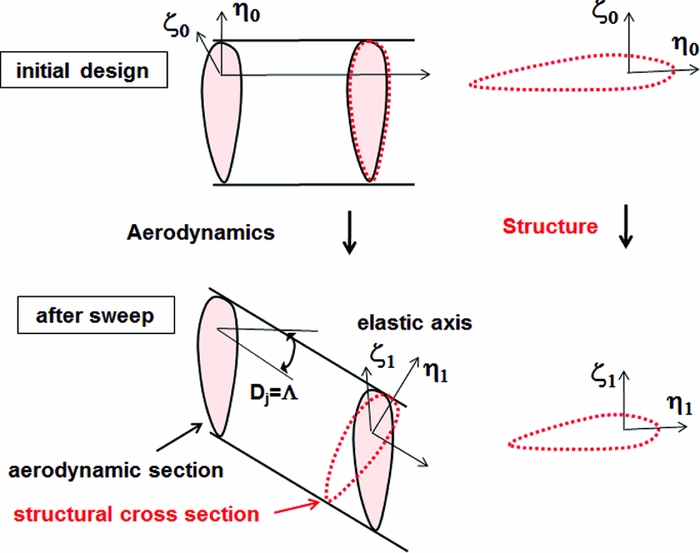
When parameterisation is applied at the radial control point (rj ), the blade section outboard of rj is displaced. Figure 2 shows the cross-sectional coordinates before and after parametric design with the design variable (i.e, sweep). When design change is made at rj , the old blade section coordinate (η0, ζ0) before the design change is displaced to the new coordinate (η1, ζ1). The aerofoil section remains the same in the free stream direction after the design change. However, the structural cross section after the design change has a narrower chord relative to the structural reference frame (e.g. elastic axis). The new design beam section maintains the same blade radius, and the solidity or structural mass remains the same.
Cross-sectional coordinates before and after parametric design (aerodynamic section in black solid line and structural section in red dotted line).

The next step is to update blade structural properties. The blade structural properties are updated using parametric equations. A transformation matrix, T represents a kinematic relationship between the ‘before’ and ‘after’ designs, and is defined for each design variable:
 $$\begin{equation}
\left\{ \begin{array}{l} {\eta _1}\\ {\zeta _1} \end{array} \right\} = {{\bf T}}\left\{ \begin{array}{l} {\eta _0}\\ {\zeta _0} \end{array} \right\},
\end{equation}$$
where the subscript ‘0’ and ‘1’ indicate before and after parametric design, respectively.
Since blade properties can be defined for various reference frames in an analysis code, we need a careful examination to identify the reference frame of the structural properties. Generally accepted definitions of structural properties are given in Ref. Reference Hodges and Dowell19, with all structural properties referenced with the elastic axis. Each of the blade structural properties (P1) after parametric design is expressed in the following general integral form for each design variable Di,j :
 $$\begin{equation}
{P_{\rm{1}}}({D_j}) = \int\!\!\!\!\int\limits_{{{\rm{A}}_{\rm{1}}}} {f({\eta _{1,}}{\varsigma _1},{D_{i,j}}}){\rm{ }}d{\eta _1}d{\varsigma _1}
\end{equation}$$
The updated structural properties (P1) are obtained after substituting the parametric equation in Equation (1) into Equation (2). Here, the new coordinate (η1, ζ1) is replaced with the old coordinate (η0, ζ0). As a result, new properties P1 will be explicitly given in terms of the known old properties and the design variable. New properties P1 typically include the offsets, blade bending and torsion stiffness, and moments of inertia. As examples, new blade flap and lag stiffness are given as:
 $$\begin{equation}
\begin{array}{*{20}{l}} {E{I_{FLAP,1}}}&{ = \int\limits_A {E{{({\zeta _1} - {\zeta _{c,1}})}^2}d{\eta _1}d{\zeta _1}} = E{I_{FLAP,0}} \cdot \cos \Lambda }\\ {E{I_{LAG,1}}}&{ = \int\limits_A {E{{({\eta _1} - {\eta _{c,1}})}^2}d{\eta _1}d{\zeta _1}} = E{I_{LAG,0}} \cdot {{\cos }^3}\Lambda } \end{array},
\end{equation}$$
where Λ is a sweep angle and the suffix c is an offset of tension centre. The radial control point, rj , is selected from r/R = 0.40, 0.55, 0.70 or 0.85, unless specified otherwise. Blade sweep is characterised by the quarter-chord line of blade and is defined positive towards the trailing edge. Dihedral is defined positive blade tip up and twist is positive leading edge (or nose) up. It is worth noting that the radial control point location should be the boundary of structural finite element and aerodynamic panel to avoid an irregularity of the property distribution inside the element or panel.
A notation for the parametric sequence of design variables uses the form, [D]i,j, where D is the value of a design variable. The ‘i’ is the name of a design variable, indicating four different design variables – ‘tw’ for twist, ‘sw’ for sweep, and ‘dh’ for dihedral, and the j indicates the location of active radial control point rj (j = 1 − 4). The design variable D is removed in the parametric sequence if rj is inactive. The parametric sequence is given as a sum if more than one design variable is applied. For example, the sequence is ‘[−5]tw3 + [4]sw3’ if −5° twist and 4° sweep are applied at r 3.
3.0 COMPREHENSIVE TOOL
CAMRAD II comprehensive analysis code(Reference Johnson15) is used in the present study. The structural model is based on beam finite element formulation with each element having 15 degrees of freedom. For the structural model, five non-linear beam elements with one rigid element inboard the hinge are used. The section aerodynamic loads are based on lifting line theory with C81 table look-up and the ONERA EDLIN unsteady aerodynamic model. Yaw flow effect is also included. For the aerodynamic model, 23 aerodynamic panels are used with a free wake option. The trim solution is obtained at every 15° azimuth.
A propulsive trim is used for all calculations. As such, the trim targets are the thrust and propulsive force, and zero roll moment. The trim variables are the collective, lateral and longitudinal cyclic pitch controls.
4.0 VIBRATION INDEX
Vibratory hub forces and moments are transferred to the rotor pylon, and the vibration can be measured by means of the N per-rev components of the transferred hub forces and moments in the hub frame. The intrusion index(Reference Crews and Hamilton20,21) is a normalised frequency response based on the measured vibrations along the three orthogonal axes of airframe, and represents the vibration at the three different locations in the aircraft under the four different flight conditions. The vibrations in the intrusion index are weighted differently for the three axes − 0.5 for the longitudinal and 0.67 for the lateral vibration relative to the vertical vibration. A generalised vibration index is therefore defined by adding the moment components to this intrusion index. Inclusion of the components is extended up to 2N per–rev (2NP) for an N-bladed rotor (i.e. eight per-rev for a four-bladed rotor):
 $$\begin{equation}
\begin{array}{l} VI = \sum\limits_{i = NP,{\rm{ }}2NP{\rm{ }}} {\left[ {{K_F}\frac{{{F_{H,i}}}}{{{W_0}}} + {K_M}\frac{{{M_{H,i}}}}{{R{W_0}}}} \right]} \\[9pt] {\rm{where }}\;\;{F_{H,i}} = \sqrt {{{\left( {0.5{F_{xH,i}}} \right)}^2} + {{\left( {0.67{F_{yH,i}}} \right)}^2} + {F_{zH,i}}^2} \\[6pt] {\rm{\qquad\;\; }}{M_{H,i}} = \sqrt {{M_{xH,i}}^2 + {M_{yH,i}}^2} \end{array}
\end{equation}$$
FH and MH are the non-rotating hub forces and moments, W 0 is the nominal aircraft weight and R is the blade radius. In this study, KF and KM are set to unity.
5.0 RESULTS AND DISCUSSION
The baselines used for parametric design were the UH-60A and UH-60 wide chord blade (WCB) rotors. The design variables considered were blade twist, sweep, dihedral and the location of the radial control point. A parametric study was performed by varying one of these design variables, while the others were held fixed. The effects of design variables on performance objectives and structural constraints were examined. This section begins with validations of the baseline configuration to establish the level of confidence in accuracy when using a comprehensive analysis tool. To understand the effects of design variables, three different parametric models were introduced. In-depth discussion will be made on the performance objective functions, as well as structural design constraints.
In the present study, the thrust, propulsive force, PL, blade section bending moments and power are defined in non-dimensional forms as follows:
 $$\begin{equation}
\begin{array}{l} {C_T} = \frac{T}{{\rho A{{(\Omega R)}^2}}}{\rm{, }}\;{C_X} = \frac{X}{{\rho AV_\infty ^2}}{\rm{ }}\\[6pt] {C_{PL}} = \frac{{PL}}{{\rho A{{(\Omega R)}^2}}},{\rm{ }}{C_{M,k}} = \frac{{{M_k}}}{{\rho A{{(\Omega R)}^2}R}}\\[6pt] {C_P} = \frac{T}{{\rho A{{(\Omega R)}^3}}}\\ {\rm{where }}\;\;A = \pi {R^2}{\rm{, and}}\\[6pt] {\rm{\quad\qquad }}k = {\rm{ }}X{\rm{(torsion)}},{\rm{ }}Y({\rm{flap}}),{\rm{ Z(chord)}}\\[6pt] {\rm{\quad\qquad }}{V_\infty } = {\rm{ freestream\ velocity}} \end{array}
\end{equation}$$
The thrust-weighted solidity used here was 0.08471 for the UH-60A main rotor and 0.09248 for the UH-60 WCB. A parametric study was performed by simulating a moderately high-speed case for the UH-60A main rotor at an advance ratio of 0.30 (40×80 wind-tunnel data, Run 52, Point 31)(Reference Norman, Shinoda, Peterson and Datta22). The power polar was computed over a full speed range from hover to high speed (m = 0.40). A typical rotor wind-tunnel trim (thrust, and rotor roll and pitching moments for trim targets) was used in all earlier studies(Reference Romander, Norman and Chang23,Reference Yeo and Romander24) . However, in this study, a propulsive trim was employed for performance analysis.
5.1 Validation using UH-60A main rotor data
A full-scale wind-tunnel test of the UH-60A main rotor was made in the USAF National Full-Scale Aerodynamics Complex (NFAC) 40- by 80-foot wind tunnel at NASA Ames Research Center(Reference Norman, Shinoda, Peterson and Datta22). The database from this test provides aerodynamic pressures, structural loads, control positions, rotor balance forces and moments, blade deformations and rotor wake measurements. This extensive test data set is a useful resource for examination of the rotor behaviours in a wide range of flight conditions.
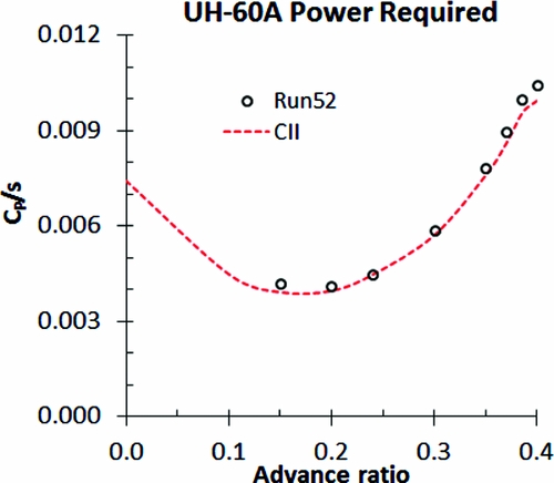
Figure 3 shows the UH-60A main rotor power polar correlated with the measured data (Run 52) covering advance ratios of 0.15 to 0.40. For performance calculation, a 3-DOF propulsive trim was used. To handle a different size of rotor, the trim targets in a non-dimensional form are scaled by (thrust-weighted) solidity. The performance prediction was made using CAMRAD II with a free wake model. The prediction seems well correlated with the measured data over a full-speed range.
Correlation of the UH-60A main rotor power polar in a full speed range.

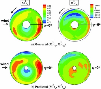
Figure 4 compares the M2cn and M2cm contours between the measured data (Run 52, Point 31) and the predictions at m = 0.30. Compared to the measured data, the M2cn prediction is higher near the 0° azimuth and also higher at the inboard of the blade in the 2nd quadrant. A phase shift of the negative down peak on the advancing side is seen from the M2cn prediction. The negative peak of M2cm on the advancing side is under-predicted. These discrepancies result from a deficiency of lifting line theory in the comprehensive code. It was demonstrated in Ref. Reference Romander, Norman and Chang23 that the use of the CFD code (OVERFLOW 2) significantly improved the predictions.
Contours of the measured and predicted UH-60A M2cn and M2cm (Run 52, Point 31, μ = 0.30).

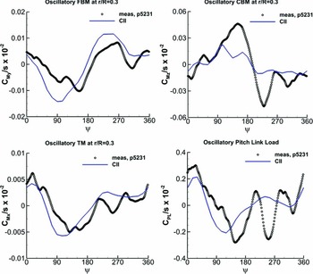
Figure 5 shows the correlation of the non-dimensional oscillatory (the mean excluded) loads at r/R = 0.30 for an advance ratio of 0.30 (Run 52, Point 31). The loads include the Flap Bending Moment (FBM), Chord Bending Moment (CBM), Torsion Moment (TM) and PL. A positive sign convention used is blade tip bent up for FBM, blade tip bent towards the trailing edge for CBM and blade tip twisted leading edge (or nose) up for TM. Consistent with Fig. 4, a phase shift of the down peak on the advancing side is observed for the FBM and TM, as well as the PL. For the CBM, the prediction shows a large under-prediction. Nonetheless, the peak-to-peak values are reasonably predicted by the comprehensive code. It was found in Ref. Reference Yeo and Romander24 that the prediction accuracy was significantly improved when using a CFD code, although the discrepancy in the CBM was apparent even with a CFD code.
Correlation of the oscillatory (FBM, CBM, TM) moments at r/R = 0.30 and PL of the UH-60A rotor (Run 52, Point 31, μ = 0.30).

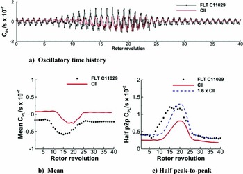
The UTTAS high-g pull-up manoeuvre condition (C11029) in the UH-60A Airloads Flight Test program(Reference Bousman and Kufeld25,Reference Bhagwat and Ormiston26) is used to investigate for the maximum design load of PL. The UTTAS manoeuvre begins near the maximum level flight speed and achieves a normal load factor (2.1 g) that significantly exceeds the steady-state lift limit of the rotor. After about 40 revolutions (9.4 seconds), the aircraft returns to the level flight (0.65 g). The PL (oscillatory time history, mean and half peak-to-peak) are compared with the measured data as shown in Fig. 6. Unexpectedly, the prediction displays a time delay by 3-4 rotor revolutions. The mean prediction showed a constant offset, and the half peak-to-peak of PL displays under-prediction by 38%. The waveform of the half peak-to-peak matches the measured data when multiplied by a factor of 1.6. Although the discrepancy in the prediction is not small, the comprehensive results can be still used to estimate the maximum design loads in the UTTAS manoeuvre.
Correlations of (a) Oscillatory time history, (b) mean and (c) half peak-to-peak of PL of the UH-60A rotor during the UTTAS manoeuvre (C11029).

Although some shortfalls in power and structural load correlations were found using the current analysis tool, CAMRAD II, power and structural load characteristics were reasonably estimated with these shortfalls. Thus, CAMRAD II is considered to be capable of carrying out this blade design study for improved performance.
5.2 UH-60A blade design sensitivity to sweep
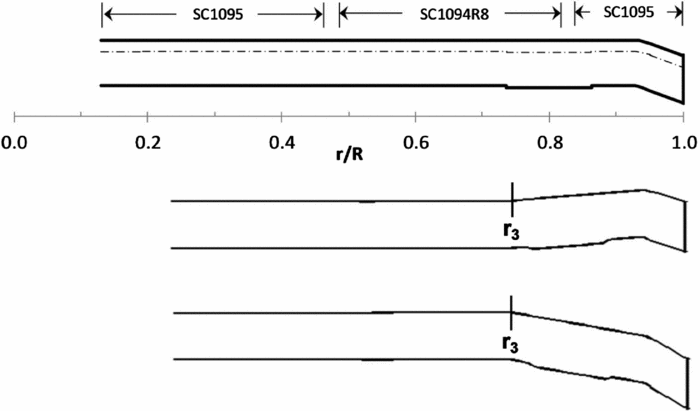
To understand the effect of design variables, a parametric study was conducted by varying each design variable (twist, sweep or dihedral) at the 3rd radial control point (rj = 0.70R), while the others were fixed at the baseline UH-60A values. Figure 7 is a sketch of the UH-60A blade planform with two parametric blade designs – one with −4o (forward) sweep and the other with 8° (backward) sweep. Since we applied a parametric design in an incremental form over the baseline configuration, the parametric blades maintain the original feature of the baseline.
A sketch of the UH-60A blade planform with two parametric blade designs – one with -4° (forward) sweep and the other with 8° (backward) sweep at r/R = 0.70 (r3).

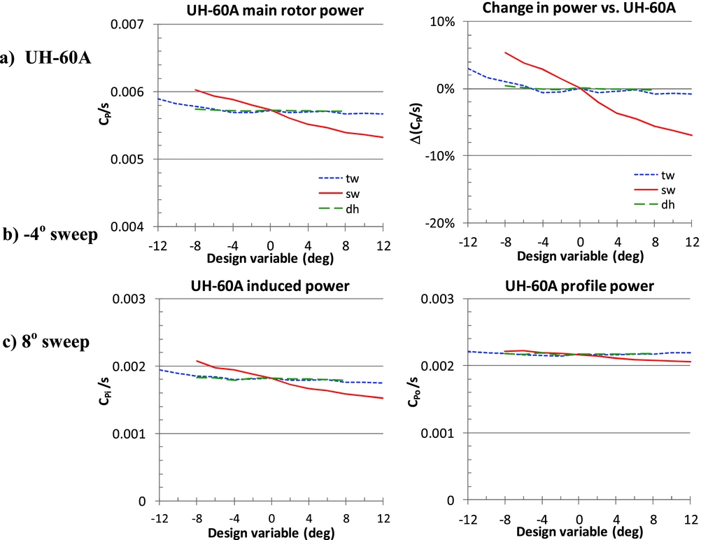
Figure 8 compares total power of the UH-60A rotor with three design variables – twist, sweep and dihedral. Main rotor total power and delta power relative to the UH-60A baseline prediction are shown for the three parametric designs. The flight condition was at μ = 0.30 (Run 52 and Point 31). It is surprising to observe such a small sensitivity of power to twist. The prediction indicates that power is sensitive only to sweep. Applying a 12° sweep to the existing UH-60A blade reduces power by 7.0%. A significant contribution to power reduction originates from the non-dimensional induced power (CPi/s). So, the sensitivity to sweep will be further investigated here.
Sensitivity of total power of the UH-60A rotor with twist, sweep and dihedral at r/R = 0.70 (Run 52, Point 31, μ = 0.30).

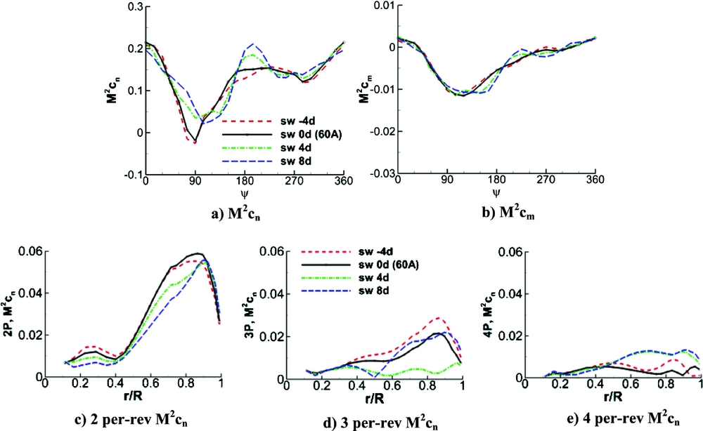
Figure 9 (a)-(b) shows time histories of M2cn and M2cm in the UH-60A rotor at r/R = 0.87 when sweep is applied at r/R = 0.70 (Run 52, Point 31). As sweep increases, the sharp negative peak of M2cn on the advancing side shifts along the azimuth, and a new positive peak is formed near 180° azimuth. Similar harmonics are seen in M2cm. Figure 9(c)-(e) shows the 2-4/rev harmonics of M2cn along the blade span. As sweep increases, the 2/rev M2cn lowers at the inboard.
Correlation of M2cn and M2cm of the UH-60A rotor with sweep at r/R = 0.70 (Run 52, Point 31, μ = 0.30).

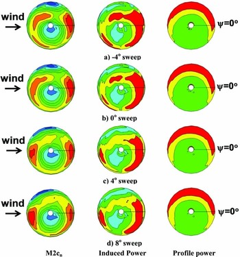
Contours of M2cn, non-dimensional induced power (CPi/s) and non-dimensional profile power (CPo/s) are shown in Fig. 10. As sweep increases at r/R = 0.70, the M2cn was redistributed over the rotor disk: the negative peak of M2cn on the advancing side shifts toward the front of the rotor, the M2cn at 0° azimuth and in the 2nd quadrant gets significantly lower, and the M2cn in 180° azimuth becomes higher. These changes in M2cn are associated directly with the induced power. The profile power shows no meaningful change.
Predicted contours of M2cn, induced power and profile power of the UH-60A rotor with sweep at r/R = 0.70 (Run 52, Point 31, μ = 0.30). The red colour indicates a high value.

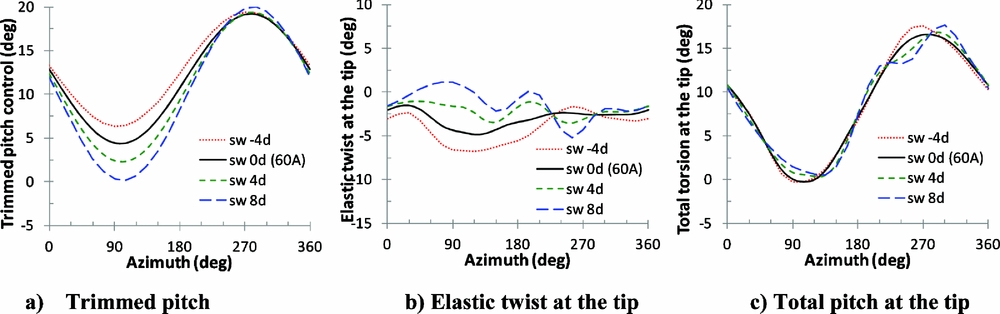
Next, torsion response is examined. Figure 11 shows time histories of the trimmed pitch control angle, the elastic twist at the blade tip and the total torsion response at the tip (Run 52, Point 31). As sweep increases, we expect that a negative (nose-down) torsion moment is generated due to the aerodynamic lift in the swept part, resulting in a negative torsional response. As expected, the trimmed pitch controls show nose-down responses on the advancing side as sweep increases. But, nose-up responses are shown for the elastic twist, which is considered beneficial for forward flight performance. The total torsion is a sum of the pitch control and the elastic twist. Interestingly, the total torsional response turns out to be small with sweep change to maintain a trim.
Torsional responses of the UH-60A rotor with sweep at r/R = 0.70 (Run 52, Point 31, μ = 0.30).

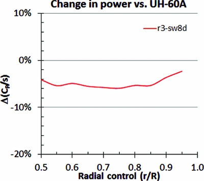
We observed a strong effect of sweep on power for the UH-60A rotor. Now, the sensitivity of power to the location of sweep is explored. For this, the radial control point (rj ) is varied from r/R = 0.5 to 0.95 with a sweep of 8°. The sensitivity of the UH-60A rotor power is shown in Fig. 12 at μ = 0.30 (Run 52, Point 31). The rotor power reduces when the control point shifts inboard from the tip, but is almost unchanged inboard from r/R = 0.85.
Total power of the UH-60A rotor with the radial control point of an 8° sweep varied from r/R = 0.50 to 0.95 (Run 52, Point 31, μ = 0.30).

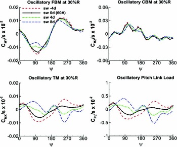
Figure 13 compares time histories of the oscillatory FBM, CBM and TM at r/R = 0.30 when sweep is applied at r/R = 0.70. Time history of the oscillatory PL is also shown. The mean values were removed for oscillatory component calculations. The oscillatory FBM is sensitive to sweep and the TM is highly sensitive, whereas the oscillatory CBM is barely sensitive. It is worth noting that the waveform of the PL is almost identical to the TM waveform at r/R = 0.30.
Oscillatory FBM, CBM and TM at r/R = 0.30, and PL of the UH-60A rotor with sweep at r/R = 0.70 (Run 52, Point 31, μ = 0.30).

A rotor designer designs a rotor blade to be operated within the maximum allowable design load. Exceeding the limit of the maximum design load, a rotor blade will undergo fracture or severe fatigue during operation. If a designer likes to increase the limit of the maximum design load, stiffening of the blade spar or other structural component reinforcement is required, which will result in an increase in the blade mass. Therefore, maintaining the limit of the maximum design load is important for new blade design.
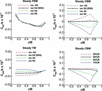
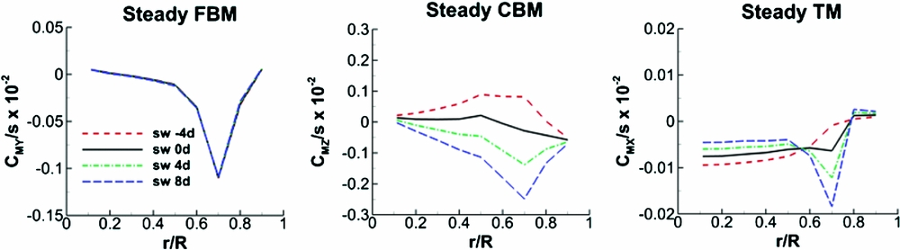
Figure 14 shows the sectional steady FBM, CBM and TM as sweep increases. Sweep varies from −4 to 8˚. The steady CBM with the 8° sweep that was varied from r/R = 0.95 to 0.70 is also plotted along the blade span. The steady FBM is found to be not sensitive. Introduction of sweep rapidly increases the negative CBM (chord lead) due to the off-axis centrifugal force in the swept part. The maximum steady CBM at r/R = 0.70 increases by a factor of 15 for 4° sweep and by 22 for 8° sweep. When the radial control point of the 8° sweep shifts outboard from r/R = 0.70, the steady CBM rapidly reduces. A sweep effect is complicated for torsion. As seen in Fig. 11, an increase in sweep generated a positive elastic twist and so a positive TM. Similarly in Fig. 14, the positive TM is observed inboard as sweep increases.
Steady FBM, CBM and TM at r/R = 0.30 with sweep varied at r/R=0.70, and steady CBM with an 8° sweep varied along the blade span for the UH-60A rotor (Run 52, Point 31, μ = 0.30).

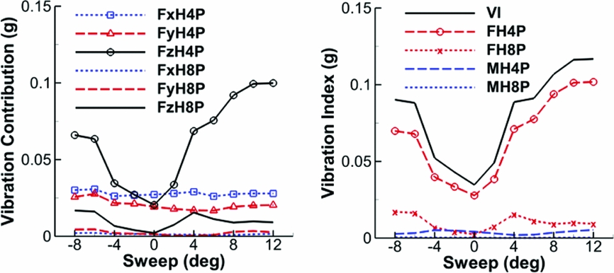
Figure 15 shows the vibrations contributed from the individual components of the 4 and 8 per-rev hub forces and the resulting vibration index. For a four-blade rotor, the 4/rev component contribution to the vibration index is expectedly higher than the 8/rev, and among the 4/rev components the 4/rev vertical shear contribution is highest. Note that the contribution from the 8/rev vertical shear is not negligible.
Vibrations contributed from the individual components of the four and eight per-rev hub forces and the vibration index with sweep varied at r/R = 0.70 for the UH-60A rotor (Run 52, Point 31, μ = 0.30).

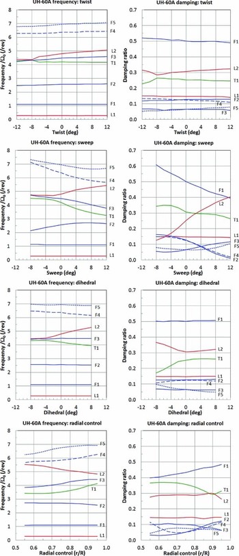
The blade frequencies and damping with design variables – twist, sweep, dihedral and radial control points – are examined in Fig. 16. Strong frequency coalescences are observed among the 1st torsion, 2nd lag and 3rd flap modes in all the cases due to the couplings in flap-torsion, extension-flap and extension-lag. So, the damping is strongly coupled between those modes. When sweep increases to 12˚, the damping of the 2nd and 4th flap modes rapidly shifts towards the instability region (see Fig. 16(b)). Note that the radial control point for twist, sweep and dihedral variation was at r/R = 0.70. When the radial control point with 8° sweep (no twist and no dihedral) shifts from the initial position of r/R = 0.70 to the outboard, the instability diminishes (see Fig. 16(d)).
Frequencies and damping ratios of the UH-60A rotor with twist, sweep, dihedral, and the radial control point of 8° sweep (Run 52, Point 31, μ = 0.30).

The sensitivity of the power and constraints was examined for the UH-60A rotor. Now, the sensitivity of a more rigorous rotor design will be examined using the UH-60 WCB having advanced aerofoils.
5.3 WCB parametric design 1 (WCB0.70R)
The UH-60 WCB has an all-composite graphite/glass-tubular spar with an increased chord (10% increase in solidity), advancedaerofoils (SC2110 and SSCA09), and a swept-tapered tip with anhedral(Reference Shinoda, Norman, Jacklin, Yeo, Bernhard and Haber18,Reference Yeo, Bousman and Johnson27) . With an increased chord, the aircraft payloads were significantly increased.
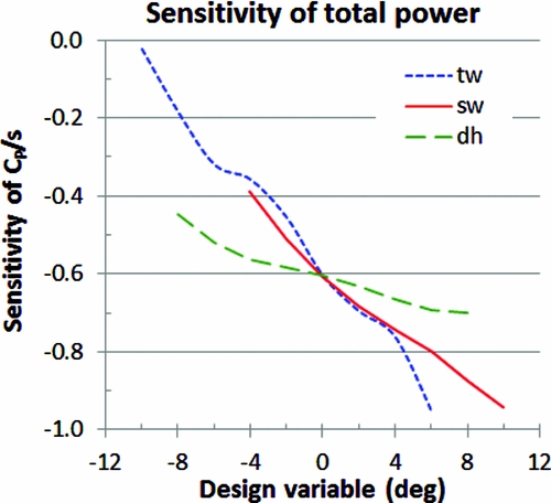
Figure 17 shows the sensitivity of total power to three design variables – twist, sweep and dihedral – for the WCB rotor. For the sensitivity representation, total power was divided by the maximum power at a 10° twist. Parameterisation was applied at one control point (rj = 0.70R) over the wide chord blade (WCB0.70R). Simulations were made for the NFAC 40x80 UH-60A forward flight condition at μ = 0.30 (Run 52 and Point 31). The power of the WCB is sensitive to all the design variables, although little sensitivity to twist or dihedral was found with the UH-60A rotor (see Fig. 8).
Sensitivity of total power of the UH-60 WCB rotor with twist, sweep and dihedral at r/R = 0.70 (Run 52, Point 31, μ = 0.30).

Since a sensitivity of total power was found with all the design variables, they were all included in the parametric design by introducing 6° twist and 8° dihedral at the (third) radial control point (r/R = 0.70) with sweep variation. Selection of the specific values of design variables was an ad hoc choice for demonstration purpose.
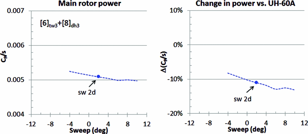
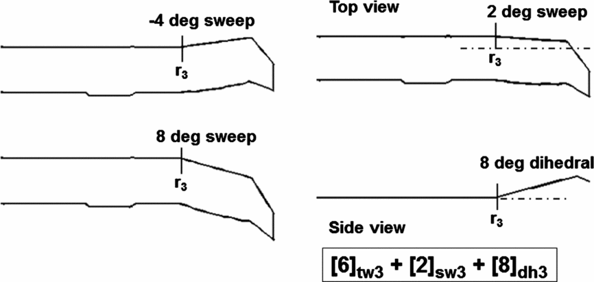
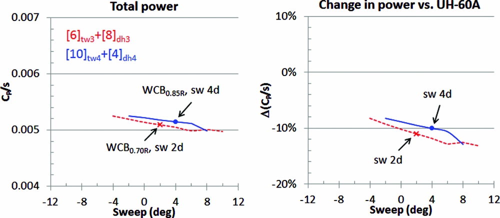
A sensitivity of power for the WCB rotor is explored with a sweep variation (−4 to 8°) at r/R = 0.70, as shown in Fig. 18. As we found earlier, total power is sensitive to sweep and most of the power reduction originates from the induced power. A choice of sweep was constrained to generate reasonably large steady chord moment. The final design blade was selected with a sweep of 2° at r/R = 0.70. As seen in this figure, at the 2° sweep the performance is not at optimum (11% power reduction relative to the UH-60A prediction), but we expect the steady moments to be reasonably smaller. Figure 19 shows a sketch of the WCB rotor blade with −4° and 8° sweep at 0.70R. For convenience, this blade is denoted as [6]tw3 + [2]sw3 + [8]dh3, where the subscript indicates the design variable and the radial control point number.
Sensitivity of power in the WCB design with twist (6°), sweep and dihedral (8°) at r/R = 0.70 (Run 52, Point 31, μ = 0.30).

A sketch of the WCB rotor blade with sweep variation at r/R = 0.70.

The sectional steady blade bending moments and TM could potentially exceed the limit of the maximum design load after parametric design. Thus, a sensitivity of the steady structural loads is examined for the WCB rotor blade. The steady blade moments along the blade span are shown in Fig. 20 with sweep variation (Run 52 and Point 31, μ = 0.30). We observed earlier in Fig. 14 that sweep significantly increased the steady CBM and moderately increased the steady TM while little sensitivity was found for the steady FBM. The same trend is found here. In fact, the steady CBM increases from −0.00058 to −0.00138 (240% increase) for a 4° sweep and to −0.00249 (433% increase) for an 8° sweep. Note that the computed steady CBM in the WCB baseline configuration was −0.00058. On the other hand, the TM shows a moderate sensitivity to sweep, which appears dominated by the aerodynamic sweep effect.
Sensitivity of the steady FBM, CBM and TM at r/R = 0.30 of the WCB rotor with sweep variation at r/R = 0.70 (Run 52, Point 31, μ = 0.30, 6° twist and 8° dihedral at r/R = 0.70).

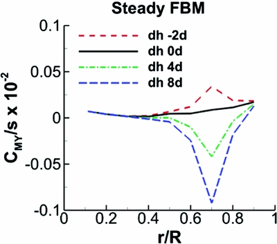
The steady FBM shows a sharp spike at r/R = 0.70, although it is not sensitive to sweep (see Fig. 20). At first, this spike surprised us, so further investigation was made. The sharp spike was found due to a FBM generated by a centrifugal force in the dihedral part of the blade (8° dihedral). Thus, the effect of the dihedral on the steady FBM is examined as shown in Fig. 21. The maximum magnitude of the steady FBM increases by a factor of 2.4 for a 4° dihedral and 5.4 for an 8° dihedral.
Sensitivity of the steady FBM at r/R = 0.30 of the WCB rotor with dihedral variation at r/R = 0.70 (Run 52, Point 31, μ = 0.30, 6o twist and 2o sweep at r/R = 0.70).

Comparison of total power between the WCB0.70R and WCB0.85R rotors with sweep variation (Run 52, Point 31, μ = 0.30).

Although a large reduction of power was made for the WCB rotor, the steady moment constraints were significantly violated. It appears that shifting the radial control point outboard from r/R = 0.70 will help to reduce the steady moments. The next blade design will have the radial control point shifted outboard.
5.4 WCB parametric design 2 (WCB0.85R)
< tex − math/ > The steady moments rapidly increase with an introduction of either sweep or dihedral due to centrifugal force. This increase in the steady moments significantly limits the feasible design space during rotor blade design. To reduce the steady moments, a few key changes are made from the WCB0.70R design – the dihedral is lowered from 8° to 4°, and the radial control point shifts from r/R = 0.70 to 0.85, while the twist increases from 6° to 10°. So, the resulting parametric design has a 10° twist and a 4° dihedral at the fourth radial control point (r/R = 0.85) over the WCB with sweep variation.
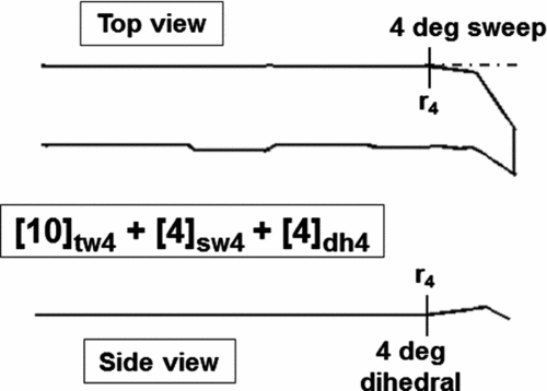
Figure 22 compares total power of the WCB0.70R and WCB0.85R rotors with sweep variation for the UH-60A condition (Run 52 and Point 31, μ = 0.30). Although the total power of both the rotors slowly reduces as sweep increases, the WCB0.85R power is generally higher than the WCB0.70R power. This is because of a trade-off in design between power and steady moments. The final WCB0.85R design ([10]tw4 + [4]sw4 + [4]dh4) is chosen with 4° sweep (see Fig. 23).
A sketch of the final WCB0.85R rotor blade design.

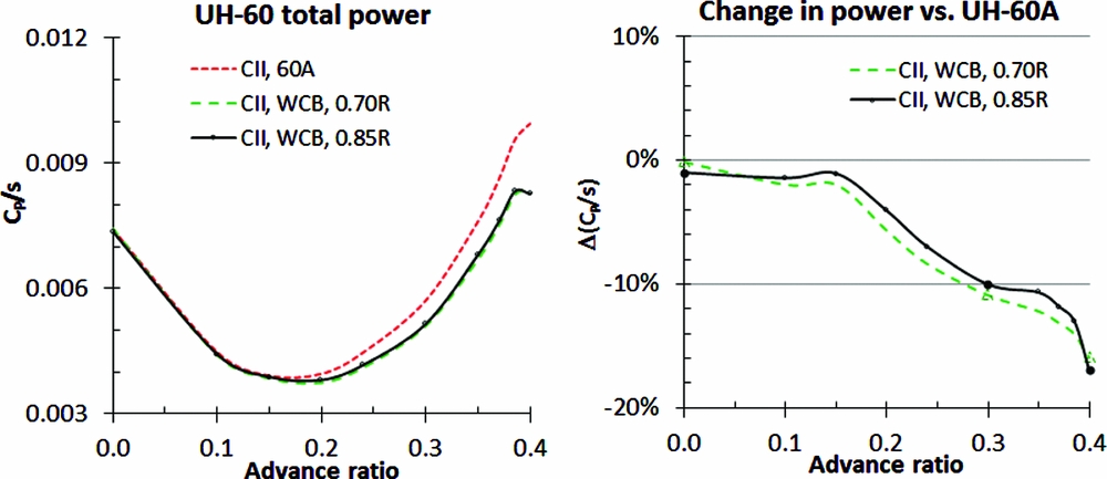
Comparison of power polar of the WCB0.70R ([6]tw3 + [2]sw3 + [8]dh3) and WCB0.85R ([10]tw4+[4]sw4+[4]dh4) rotors in a full speed range (Run 52).

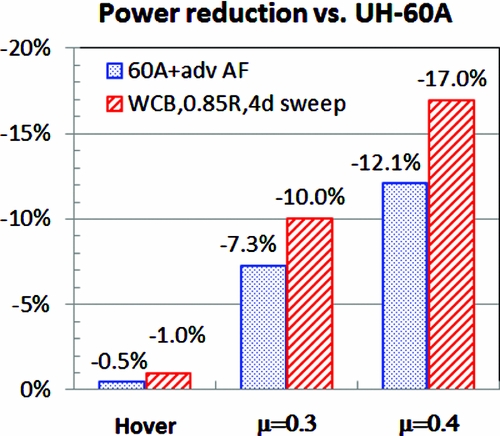
Figure 24 compares power polar of the WCB0.70R and WCB0.85R rotors against the UH-60A main rotor power prediction. As observed in Figs. 20 and 21, the WCB0.85R rotor has shown significant increases in the steady moments from the baseline WCB rotor configuration. Since the WCB0.85R rotor was designed to improve the steady moment issue found in the previous rotor, its rotor power is expected higher as a trade-off. This happened as shown in the figure, but in hover and at μ = 0.40, the WCB0.85R power is slightly lower than the WCB0.70R. The WCB0.85R power reduction is 1.0% in hover, 10.0% at μ = 0.30 and 17.0% at μ = 0.40, relative to the UH-60A power. This power reduction is largely owing to the use of advanced aerofoils. It is worth noting that UH-60A was designed primarily for hover, so a large performance benefit would be expected in forward flight design. The power of the UH-60A rotor with the advanced aerofoils was compared in Fig. 25. The benefit of the blade planform change alone can be roughly estimated by the difference of power between the WCB0.85R rotor and the UH-60A rotor having the same advanced aerofoils. Thus, the planform change in the WCB0.85R rotor would give reductions of 0.5% in hover, 2.7% at μ = 0.30 and 4.9% at μ = 0.40 against the UH-60A rotor.
Comparison of total power between than WCB0.85R and the UH-60A having advanced aerofoils at various speeds.

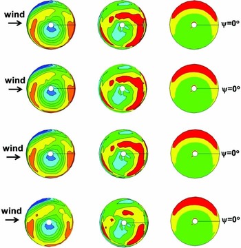
Contours of M2cn, induced power (CPi/s) and profile power (CPo/s) in the design are shown in Fig. 26 at μ = 0.30 (Run 52, Point 31). Small sensitivity to sweep variation is found for M2cn and the induced power. The induced power at the 0° azimuth gets lower as sweep increases.
Predicted contours of M2cn and the induced and profile powers of the WCB rotor with sweep at r/R = 0.85 (Run 52, Point 31, μ = 0.30, 10° twist and 4° dihedral at r/R = 0.85). The red colour indicates a high value.

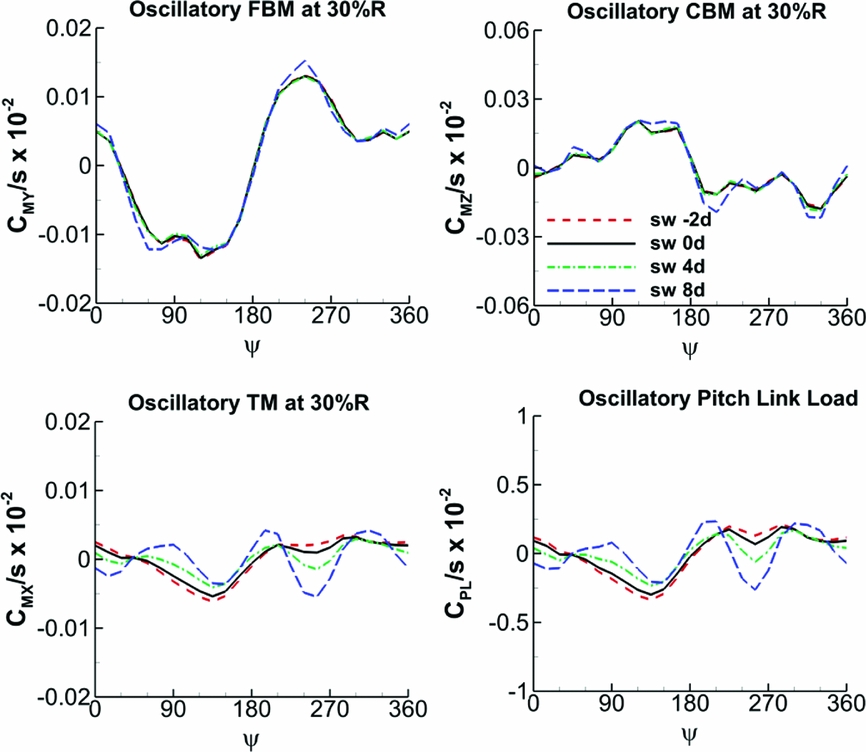
Figure 27 compares time histories of the oscillatory FBM, CBM and TM at r/R = 0.30 of the WCB0.85R rotor with the sweep varied from −2° to 8°. The oscillatory PLis also shown. The same UH-60A flight condition is used (Run 52 and Point 31, μ = 0.30). The oscillatory TM, and so the PL, show sensitivity with sweep variation, but their peak-to-peak values stay almost the same.
Sensitivity of the oscillatory FBM, CBM, TM at r/R = 0.30 and the oscillatory PL of the WCB rotor with sweep variation at r/R = 0.85 (Run 52, Point 31, μ = 0.30, 10° twist and 4° dihedral at r/R = 0.85).

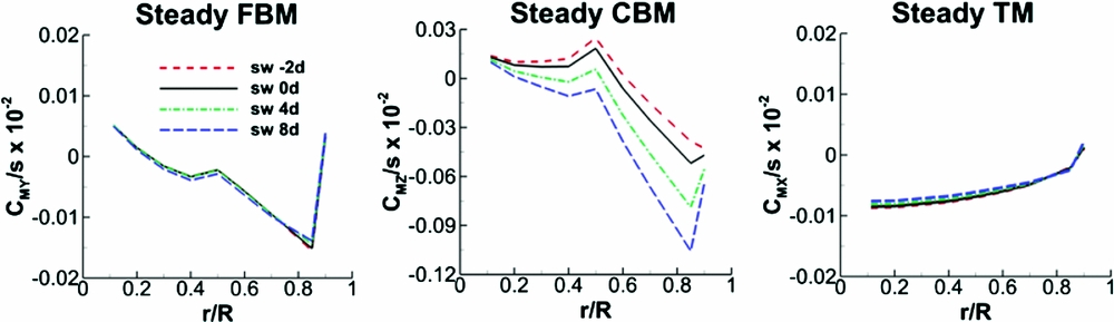
The steady CBM is expected to decrease significantly when the location of the sweep control point shifts from r/R = 0.70 to 0.85. In Fig. 28, adding a 4° (backward) sweep at r/R = 0.85 shows an increase in the maximum steady CBM from −0.00052 to −0.00079 (in magnitude; 52% increase). This magnitude increase is equivalent to a 35% increase relative to the WCB baseline value (−0.00058). However, we do not have sufficient information for judgment on whether this maximum bending load increase will cause a structure failure or not, so future investigation on this matter is necessary.
Sensitivity of the steady FBM, CBM and TM at r/R = 0.30 of the WCB rotor with sweep variation at r/R = 0.85 (Run 52, Point 31, μ = 0.30, 10° twist and 4° dihedral at r/R = 0.85).

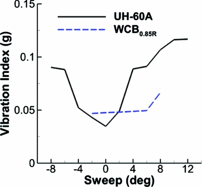
Figure 29 compares the vibration index between the UH-60A and WCB0.85R design (Run 52, Point 31). The WCB0.85R design maintains a low vibration level as sweep increases. A sharp rise in vibration is found from the UH-60A rotor when sweep is introduced.
Vibration index between the UH-60A and WCB0.85R rotors with sweep variation at r/R = 0.85 (Run 52, Point 31, 10° twist and 4° dihedral at r/R = 0.85).

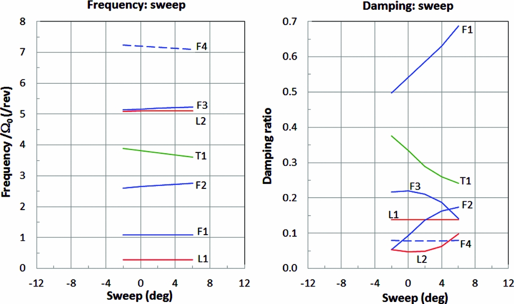
Figure 30 shows the frequencies and damping ratios with sweep variation. The frequencies appear coupled between the 2nd lag and 3rd flap modes and between the 1st torsion and 2nd flap modes. All the modes appear stable with sweep variation.
Sensitivity of the frequencies and damping ratios of the WCB rotor with sweep variation at r/R = 0.85 (Run 52, Point 31, μ = 0.30, 10° twist and 4° dihedral at r/R = 0.85).

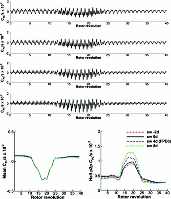
Figure 31 shows the mean and half peak-to-peak values of PL for the UTTAS pull-up condition (C11029) with sweep variation. The mean PL is not sensitive to sweep, but the half peak-to-peak magnitude is sensitive. An introduction of a 4° sweep at r/R = 0.85 in the WCB0.85R design increases the half peak-to-peak PL from 0.010 to 0.012 (20% increase). This increase could be accepted if the blade stiffness is reinforced at the sections. From all these findings, we observed that an introduction of sweep or dihedral in the blade design would increase the sectional steady moments due to centrifugal force. To overcome this difficulty, more rigorous design efforts are necessary by the redistributing of the blade section mass by means of chord tapering or performing structural redesign of the blade cross sections.
Sensitivity of the PL (oscillatory time history, mean and half peak-to-peak) of the WCB rotor with sweep variation at r/R = 0.85 during the UTTAS manoeuvre (C11029, 10° twist and 4° dihedral at r/R = 0.85).

6.0 CONCLUSIONS
This design study applied parameterisation to rotor blade for improved performance. In the design, parametric equations were used to represent blade planform changes over the existing rotor blade model. Complex geometries of a rotor blade were successfully simulated using the present parametric design tool.
UH-60A and UH-60 WCB rotors were used as the baseline configurations for parametric blade design. Design variables included blade twist, sweep, dihedral and the radial control point. Updates to the blade structural properties with changes in the design variables allowed accurate evaluation of performance objectives and realistic structural constraints – blade stability, steady moments (flap bending, chord bending and torsion) and the UTTAS manoeuvre PL.
Performance improvement was demonstrated with multiple parametric designs. Adopting advanced aerofoils for the UH-60A rotor resulted in a power reduction by 0.5% in hover, 7.3% at μ = 0.30 and 12.1% at μ = 0.40. Using the best design (WCB0.85R with a 4° sweep) in the present study, the predicted power reduction was 1.0% in hover, 10.0% at μ = 0.30 and 17.0% at μ = 0.40 relative to the baseline UH-60A rotor. But these were obtained with a 35% increase in the steady CBM at μ = 0.30 and a 20% increase in the half peak-to-peak PL during the UTTAS manoeuvre. Low vibration was maintained for the WCB0.85R rotor.
The structural constraints often confined the design space and governed the optimal solutions. The key for a better solution is to find the feasible design space which is less dependent on these constraints. More rigorous design efforts, such as chord tapering and/or structural redesign of the blade cross section, would enlarge the feasible design space and likely provide significant performance improvement. Due to shortfalls in comprehensive code predictions, the use of high-fidelity CFD methods is expected to enhance the accuracy of findings in this study.
ACKNOWLEDGEMENTS
The author would like to express many special thanks to Dr. Wayne Johnson, NASA Ames Research Center and Mr. Thomas Maier, AFDD, for their invaluable insights, guidance and encouragement through the completion of this work.